Table of Contents
Quick Links
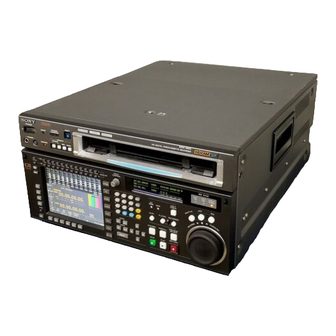
HD DIGITAL VIDEOCASSETTE RECORDER
SRW-5000
FORMAT CONVERTER BOARD
HKSR-5001
DIGITAL BETACAM PROCESSOR BOARD
HKSR-5002
RGB PROCESSOR BOARD
HKSR-5003
Note
The supplied CD-ROM includes operation manuals for the SRW-5000 series of
digital camcorders (English, Japanese, French and German versions).
For more details, see page 1-6 "Using the CD-ROM Manual."
OPERATION MANUAL
1st Edition
Serial No. 10101 and Higher
[English]
Table of Contents

Related Manuals for Sony SRW-5001


Summary of Contents for Sony SRW-5001
- Page 1 HD DIGITAL VIDEOCASSETTE RECORDER SRW-5000 FORMAT CONVERTER BOARD HKSR-5001 DIGITAL BETACAM PROCESSOR BOARD HKSR-5002 RGB PROCESSOR BOARD HKSR-5003 Note The supplied CD-ROM includes operation manuals for the SRW-5000 series of digital camcorders (English, Japanese, French and German versions). For more details, see page 1-6 “Using the CD-ROM Manual.” OPERATION MANUAL [English] 1st Edition...
- Page 2 WARNING To prevent fire or shock hazard, do not expose the unit to rain or moisture. To avoid electrical shock, do not open the cabinet. Refer servicing to qualified personnel only. THIS APPARATUS MUST BE EARTHED. AVERTISSEMENT This symbol is intended to alert the user to the presence of uninsulated “dangerous voltage”...
- Page 3 WARNING: THIS WARNING IS APPLICABLE FOR Important Safety Instructions OTHER COUNTRIES. • Read these instructions. 1. Use the approved Power Cord (3-core mains lead)/ • Keep these instructions. Appliance Connector/Plug with earthing-contacts that • Heed all warnings. conforms to the safety regulations of each country if •...
- Page 4 CAUTION For the customers in Europe The unit is not disconnected from the AC power source This product with the CE marking complies with both the (mains) as long as it is connected to the wall outlet, even if EMC Directive (89/336/EEC) and the Low Voltage Directive the unit itself has been turned off.
-
Page 5: Table Of Contents
Table of Contents 1-1 Features ................... 1-1 Chapter 1 1-1-1 Features of the SRW-5000 ............. 1-1 Overview 1-1-2 Features of the Control Panel ..........1-3 1-2 Optional Accessories ..............1-5 1-3 Using the CD-ROM Manual ............1-6 1-3-1 CD-ROM System Requirements ..........1-6 1-3-2 Preparations ................ - Page 6 Table of Contents 4-3 TC Menu ..................4-20 Chapter 4 4-3-1 Setting the Time Data (TIMER SEL/RESET/SET/HOLD) 4-21 Menu Settings 4-3-2 Setting the Time Code Reader (TCR SEL) ......4-24 4-3-3 Setting the Time Code Generator (TCG SOURCE/MODE) 4-24 4-3-4 Selecting the Time Code Running Mode (RUN MODE) ..4-25 4-3-5 Selecting the Drop Frame Mode (DF/NDF) ......
- Page 7 5-1 Preparing for Recording ..............5-1 Chapter 5 5-1-1 Setting Switches and Menus ..........5-1 Recording/Playback 5-1-2 Selecting Audio Signals ............5-2 5-1-3 Adjusting the Recording Level ..........5-3 5-1-4 Simultaneously Monitoring Playback of Video and Audio Signals Being Recorded ............5-4 5-2 Recording ..................
- Page 8 Table of Contents Menu List .................... A-13 Appendix Items Relating to VTR Operations (001~) ........A-14 Items Relating to Operation Panels (101~) ........A-19 Items Relating to Remote Interface (201~) ........A-22 Items Relating to Editing (301~) ........... A-23 Items Relating to Prerolling (401~) ..........A-25 Items Relating to Recording Protection (501~) ......
-
Page 9: Features
Audio recording can be switched between the digital audio signal multiplexed with the HD SDI signal and the audio signal from an AES/EBU digital interface........................................... 1) HDCAM is a trademark of Sony Corporation. Chapter 1 Overview... - Page 10 In 720×1280 mode, D1 SDI or analog composite providing greater efficiency in cassette management signals can be output. and editing........................................... 1) A contact-free system for writing, reading, and modifying video cassette-related information on IC memory-bearing labels. Tele-File is a trademark of Sony Corporation. Chapter 1 Overview...
-
Page 11: Features Of The Control Panel
Features for Ease of Operation Menu-driven operations for a variety of purposes Compact, lightweight, low power consumption Eight menus are displayed on the 130 × 95 mm (5 The VTR is small and light enough to be used in inches × 3 outside broadcast vans or in EFP (Electronic Field inches) color display and are set using Production) assignments. - Page 12 1-1 Features • Use the scrollable VTR SETUP menu to display the A full range of editing functions items necessary for making initial settings, and to directly change settings without registering them with Two SRW-5000 units can be connected allowing the function buttons for each menu.
-
Page 13: Optional Accessories
1-2 Optional Accessories The following accessories can be used with the SRW- 5000. HKSR-5001 Format Converter Board This allows format conversion described below: • 2-3 pull-down (23.98PsF to 59.94i) • Conversion between 1080 and 720p • 720p to 525i HKSR-5002 Digital Betacam Playback Board This allows you to play back Digital Betacam tapes and output SD and HD (in case of 1080;... -
Page 14: Using The Cd-Rom Manual
If you lose the CD-ROM disc or become unable to 1-3-2 Preparations read its content, for example because of a hardware failure, contact a Sony service representative. The following software must be installed on your computer in order to use the operation manuals contained in the CD-ROM disc. -
Page 15: Locations And Functions Of Parts
2-1 Control Panel The control panel consists of the following sections: • Lower control panel • Upper control panel • System set-up panel Upper control panel 4 Display section (see page 2-8) SRW-5000 HD DIGITAL VIDEO CASSETTE RECORDER 5 Search control section (see page 2-9) 3 Tape transport control section (see page 2-7) 2 Editing control section (see page 2-6) -
Page 16: Upper Control Panel
2-1 Control Panel 2-1-1 Upper Control Panel 1 POWER switch 2 ERROR indicator 3 WARNING indicator 4 EJECT button 5 Format indicators SRW-5000 HD DIGITAL VIDEO CASSETTE RECORDER EJECT POWER ERROR WARNING REMOTE PHONES CHANNEL ETHERNET 1(9P) 2(50P) CONDITION 6 REMOTE buttons Cassette compartment 7 CHANNEL CONDITION indicators 8 PHONES level control... - Page 17 7 CHANNEL CONDITION indicators These show the status of the playback signal. Blue: The playback signal status is satisfactory. Yellow: The playback signal status is satisfactory. However, if this indicator remains lit continuously, head cleaning is required. Red: The playback signal has deteriorated. However, if this indicator remains lit continuously, head cleaning or internal inspection is required.
-
Page 18: Lower Control Panel
2-1 Control Panel 2-1-2 Lower Control Panel 1 Menu Control Section 1 MONITOR R buttons 3 MULTI CONTROL knob 2 MONITOR L buttons MULTI CONTROL CH10 CH11 CH12 MONITOR HOME OVER OVER OVER OVER OVER OVER OVER OVER OVER OVER OVER OVER 9 DISPLAY button... - Page 19 4 Menu selection buttons Menu display: These select the menu screen displayed on the display. This displays the menu screen selected by the menu HOME button: Press this to go to the HOME menu selection buttons. screen. The home menu provides settings for the Each menu screen shows the functions assigned to the function buttons ([F1] to [F10]), and shows basic VTR operations and editing operations.
-
Page 20: Editing Control Section
2-1 Control Panel 0 FULL/FINE button 2 Editing Control Section This selects the audio level meter display range. FULL: The audio level meter display is from –60 dB to 0 dB, or –40 dB to +20 dB. Select which of 1 Numeric buttons and +/–... - Page 21 5 SET button 3 Tape Transport Control Section Press to finalize input data. 6 INPUT CHECK button 1 STANDBY button While you hold down this button, the input signal is 2 PREROLL button output from the monitor output connector, so that you 3 PREVIEW/REVIEW button can monitor the input video and audio.
-
Page 22: Display Section
2-1 Control Panel 4 REC/EDIT (recording/edit) button 4 Display Section Press this button while holding down the PLAY button to start recording. 1 OEL display If you press this button in play mode, manual editing 2 REF SYNC indicators begins. After setting edit points, if you press this button while the AUTO button is lit, automatic editing is performed. - Page 23 5 REC INHIBIT indicator 5 Search Control Section The status of this indicator depends on the setting of the [F2] (REC INH) button in the HOME menu and the state of the record-protect plug on the cassette. 1 SHUTTLE button Setting of the [F2] State of the record- REC INHIBIT...
- Page 24 2-1 Control Panel 4 Search dial Rotate to search for edit points. Rotate the dial clockwise for forward playback (the B indicator lights up) or counterclockwise for reverse playback (the b indicator lights up). The x indicator lights up while the VTR is in stop mode.
-
Page 25: System Set-Up Panel
2-1-3 System Set-Up Panel Lift the lower control panel up to its horizontal position to access the system set-up panel. CONTROL PANEL connector CONTROL PANEL Card slot eject button Memory stick eject button Memory stick receptacle PCM CIA card slot Harness restraint For details, see “3-4 Using a Memory Stick”... -
Page 26: Connector Panel
2-2 Connector Panel 2-2 Connector Panel 1 ANALOG I/O section (see page 2-13) 2 DIGITAL I/O section (see page 2-15) 3 Remote input/output section 4 Power supply (see page 2-16) (see page 2-16) 2-12 Chapter 2 Locations and Functions of Parts... - Page 27 1 ANALOG I/O (input/output) section 1 MONITOR OUTPUT L/R connectors 2 AUDIO OUTPUT CH1 to CH4 connectors 3 REF. INPUT 1 connectors and 75 Ω termination switch ANALOG I/O AUDIO OUTPUT REF INPUT 2 (OPTION) 75Ω 75Ω 4 REF. INPUT 2 connectors and 75 Ω termination switch MONITOR OUTPUT TIME CODE HD REF OUT...
- Page 28 2-2 Connector Panel 4 REF. INPUT 2 connectors (BNC) and 75 Ω 8 TIME CODE OUT connector (XLR-3-31, termination switch female) Input a reference video signal of the field frequency Outputs the following time codes according to the selected for the format converter output. Select HD or VTR operation mode.
- Page 29 2 DIGITAL I/O (input/output) section DIGITAL I/O (AES/EBU) DIGITAL I/O INPUT OUTPUT HD SDI INPUT AUDIO AUDIO INPUT MONITOR CH1/2 CH3/4 CH1/2 CH3/4 1 HD SDI INPUT A/B connectors B INPUT MONITOR B(OPTION) CH5/6 CH7/8 CH5/6 CH7/8 HD SDI OUTPUT 3 MONITOR CH9/10 CH11/12...
- Page 30 2-2 Connector Panel 5 REMOTE 1-I/O (9P) connectors 3 Remote input/output section (D-sub 9-pin) Use this, with the supplied 9-pin remote control cable, to connect the unit to another SRW-5000 unit or 1 RS232C connector another HD VTR unit to carry out editing with a BVE- 2 REMOTE1-IN connector series editor BVE-900/2000/9000/9100.
-
Page 31: Setting Up The Vtr
3-1 Connecting External Equipment 3-1-1 Making HD Digital Connections This example shows the connections when using an HDW-F500 as player and an SRW-5000 as recorder, in 59.94i or 60i mode. HDW-F500 (Player) HD SDI OUTPUT REMOTE (9P) AUDIO OUTPUT HD SDI INPUT DIGITAL I/O INPUT HD SDI OUTPUT SRW-5000 (Recorder) -
Page 32: Making Ntsc/Pal Digital Connections
3-1 Connecting External Equipment 3-1-2 Making NTSC/PAL Digital Connections This example shows how to connect two VTRs, an SRW-5000 as the players and a DVW-500 D-1 Component Digital VTR as the recorder. SRW-5000 (Player) [Input] SD SDI OUT REMOTE 1-IN COMPOSITE VIDEO OUTPUT 9-pin remote control cable... -
Page 33: Cascade Connection
3-1-3 Cascade Connection Note This example shows how to connect multiple SRW- 5000 VTRs together for simultaneous recording. On the recording VTRs, set the VTR SETUP menu item 613 “TC OUTPUT SIGNAL IN REGENE MODE” to “through”. HDW-F500 (Player) HD SDI OUTPUT TIME CODE OUT TIME CODE IN HD SDI INPUT... -
Page 34: Reference Signals
3-2 Reference Signals 3-2 Reference Signals This section describes how reference signals for the video output are selected. 3-2-1 Reference Signals for Output Video Depending on the operating condition, VTR SETUP menu settings, and the input signal, the video output signal from the VTR can be synchronized as follows. -
Page 35: Reference Signal Connections
3-2-2 Reference Signal Connections Make the reference signal connections as follows, according to your recording or playback requirements. Reference signal connections For recording signals from a switcher or signal generator Reference signal Switcher or signal generator HD SDI INPUT REF. IN 75Ω... - Page 36 3-2 Reference Signals For playback Reference signal REF. IN HD serial input HD SDI OUTPUT monitor 1/2/3 MONITOR 75Ω termination switch: ON Note The following signals can be used as a reference signal. • HD trilevel SYNC signal of an appropriate field frequency for external synchronization •...
-
Page 37: Handling Cassettes
3-3 Handling Cassettes 3-3-1 Recommended Cassettes 3-3-2 Inserting and Ejecting Cassettes For recording and playback: inch HDCAM-SR cassettes. Always turn on the VTR before inserting or ejecting The maximum recording time is as shown in the cassettes. following table. System Inserting a cassette frequency 29.97/30 Hz... -
Page 38: Preventing Accidental Erasure
3-3 Handling Cassettes Removing slack in the tape 3-3-3 Preventing Accidental Press one of the reels in slightly, then carefully rotate it Erasure in the direction of the arrow until it stops. To prevent accidental erasure of material recorded on a tape, push in the record-protect plug. -
Page 39: Using A Memory Stick
3-4 Using a Memory Stick When a Memory Stick is inserted in the VTR, the file Types of Memory Stick data can be stored on the Memory Stick, which enables you to share data among VTRs. There are two types of Memory Stick: MagicGate Memory Stick that are equipped with the MagicGate copyright protection technology and general Memory Inserting a Memory Stick... - Page 40 Do not turn off the power of the unit or remove the Memory Stick. This may damage the data. Memory Stick and are the trademarks of Sony Corporation. MagicGate Memory Stick and are the trademarks of Sony Corporation. 3-10 Chapter 3 Setting Up the VTR...
-
Page 41: Registering And Storing Menu Settings
4-1 Registering and Storing Menu Settings The operating conditions of the VTR are set using the menu operation section on the lower control panel. HOME menu Menu items are divided among eight different menus (HOME, TC, VIDEO, AUDIO, CUE, PF1, PF2, SET TC menu UP). -
Page 42: Registering Items To The Vtr Setup Menu
4-1 Registering and Storing Menu Settings Press the TC button. Registering items The first page of the TC menu appears in the display. P L A Y L O C K T I M E R S E L L T C I N T R P T G A T I M E R... -
Page 43: Vtr Memory Bank Function
To unregister the selected item Press the [F6] (BLANK) button. Current menu settings in the VTR (CURRENT SETUP). These settings are stored When a function button with other than the default outside the VTR memory assignment is selected, the [F4] (KEY DEF.) banks even when the power Storing/recalling is off. - Page 44 4-1 Registering and Storing Menu Settings Press the [F1] (VTR BANK) button. To add or change a title for VTR settings after storing them to the VTR memory bank The VTR BANK menu appears in the display. Move the cursor (B) to the number of the VTR memory bank where the settings are stored, then press the [F6] (EDIT TITLE) button.
-
Page 45: Memory Stick Function
The menu settings are recalled from the selected Recalling menu settings from a VTR VTR memory bank. memory bank When the recalling process has been completed, the title of the VTR bank appears under CURRENT SETUP in the display. V T R B A N K V T R B A N K C U R R E N T S E T U P T I T L E E D I T C U R R E N T S E T U P... - Page 46 4-1 Registering and Storing Menu Settings Formatting a memory stick Storing the contents of the VTR memory banks to a memory stick A memory stick must be formatted before you can use them. 4,5,6 Insert the memory stick. Press the SET UP button. Press the SET UP button.
- Page 47 Storage begins. F O R M A T C A R D B A N K 0 C U R R E N T S E T U P After the storage is complete, the title of the VTR Destination C A R D ( B A S E B A L L ) C F O O T B A L L...
- Page 48 4-1 Registering and Storing Menu Settings Press the [F2] (MEMORY CARD) button. Press the [F9] (COPY) button. The MEMORY CARD menu appears in the A message asking you to confirm the operation display. appears in the display. Press the [F9] (COPY) button while holding down F O R M A T C A R D B A N K 0 C U R R E N T S E T U P...
- Page 49 Press the [F2] (MEMORY CARD) button. F O R M A T C A R D B A N K 0 C U R R E N T C U E S E T The MEMORY CARD menu appears in the Destination C A R D ( B A S E B A L L )
- Page 50 4-1 Registering and Storing Menu Settings To return to the MEMORY CARD menu Recalling a cue point list from a memory Press the [F3] (SHOW SETUP) button again. stick Press the [F8] (DIRECTION) button to select the Recalling a cue point list from a memory stick replaces , direction.
-
Page 51: Adding Titles To The Data
Press the [F7] (SET LETTER) button or the center 4-1-6 Adding Titles to the Data cursor button. When storing data to a memory bank in a memory The selected letter is entered. stick or the VTR, you can add a title to the data to make data management easier. -
Page 52: Functions
4-1 Registering and Storing Menu Settings 4-1-7 Details on VTR Memory 4-1-8 Memory Stick Data Bank and Memory Stick Compatibility Functions Data copied onto a memory stick can be used on control panels connected to other SRW-5000 VTRs. Most setting of most items can be stored to a VTR Although data is completely compatible between memory bank or a memory stick, with the exception of VTRs with different optional equipment, take note of... -
Page 53: Home Menu
4-2 HOME Menu To activate the HOME menu The HOME menu sets the basic VTR operation Press the HOME button. conditions for recording, playback, and editing. The HOME, VIDEO, AUDIO, TC, PF1 and PF2 To change the HOME menu page menus show information that includes the VTR Press the ALT button. -
Page 54: Selecting The Output Signals (Pb/Ee)
4-2 HOME Menu Note 4-2-1 Selecting the Output When PB/PB is selected in shuttle mode during Signals (PB/EE) HDCAM playback, audio output is muted for playback speeds of more than –1 or +2 times normal speed. The audio/video output signals from the line output and monitor output connectors can be temporarily changed from their current settings to another set of settings by pressing the [F1] (PB/EE) button. -
Page 55: Selecting The Edit Mode And Edit Channel
4-2-5 Still-Picture Output 4-2-3 Selecting the Edit Mode (FREEZE) and Edit Channel (ASSEMBLE, INS TC, INS VIDEO and INS For still-picture output, press the ALT/[F3] (FREEZE) AUDIO) buttons. The picture that was playing just before the button was pressed will be frozen on the screen. Make Select assemble or insert edit mode. -
Page 56: Setting The Preroll Time (Preroll Time)
4-2 HOME Menu 4-2-6 Setting the Preroll Time 4-2-7 Selecting DMC Playback (PREROLL TIME) (DMC) Set the preroll time by pressing the ALT/[F6] In DMC (Dynamic Motion Control) playback mode, (PREROLL) buttons. the VTR plays back a tape segment at a specified You can set a preroll time of 0 to 30 seconds in 1- variable speed of –1 to +2 times normal playback second units. - Page 57 Adjusting the stop position when a stop T A P E L O C K code is detected: [F4] L T C I N T R P T C R D E T E C T B E E P When a stop code is detected, you can adjust the o f f A I N - - : - - : - - : - -...
- Page 58 4-2 HOME Menu To specify the recording start position Recording stop codes: [F7] Press the [F5] (REC ADJUST) button, to specify how many seconds before the SOM point the recording of To record stop codes, press the [F7] (CODE REC) the stop code should start.
- Page 59 Press the HOME button. The HOME menu screen appears. Press the ALT/[F8] (STOP CODE) buttons. The stop code menu screen appears. Press the [F8] (CODE ERASE) button to select “on”. Pressing the button toggles betwen “on” and “off”. Press the REC/EDIT button. To abandon the operation at any point Press the STOP button.
-
Page 60: Tc Menu
4-3 TC Menu 4-3 TC Menu To activate the TC menu The TC menu allows you to set time code-related Press the TC button. items through a single menu. The HOME, TC, VIDEO, AUDIO, PF1 and PF2 menus show To change the TC menu page information that includes the VTR operation mode, Press the ALT button. -
Page 61: Setting The Time Data (Timer Sel/Reset/Set/Hold)
4-3-1 Setting the Time Data (TIMER SEL/RESET/SET/HOLD) P L A Y L O C K T I M E R S E L L T C I N T R P T C R T I M E R The display shows the following types of time data: R E S E T A I N - - : - - : - - : - - A O U T - - : - - : - - : - -... - Page 62 4-3 TC Menu Selecting the time code and the user bits to be recorded Use the [F6] (REGENE SOURCE), [F7] (TCG MODE), and [F9] (DF/NDF) buttons in the TC menu to specify the time code and the user bits to be recorded.
- Page 63 To cancel entered values Setting time codes Press the CLR button. To set time codes, select “prst” with the [F7] (TCG Press the SET UP button to set the entered MODE) button in the TC menu and then follow the value.
-
Page 64: Setting The Time Code Reader (Tcr Sel)
4-3 TC Menu Resetting time data To pause the current time Press the [F2] (TIMER RESET) button. Press the [F4] (TIMER HOLD) button. The internal time code generator is reset according to The time is paused only while the button is held down. the setting of the [F1] (TIMER SEL) button. -
Page 65: Selecting The Time Code Running Mode (Run Mode)
Menu [F6] (REGENE [F7] (TCG Setting 4-3-4 Selecting the Time Code SOURCE) MODE) Running Mode (RUN MODE) Internal prst Time codes can be freely set Press the [F8] (RUN MODE) button to select the time (Preset) using the code running mode. internal time code generator free: The time code advances when the power is on... -
Page 66: Area (Tc2 Sel)
4-3 TC Menu 4-3-6 Selecting the Content of the Second Time Code Display Area (TC2 SEL) Select the content of the second time code display area using the [F10] (TC2 SEL) button. Setting Time data displayed No display LTC value read from the time code reader Auto When the playback speed is within the range ±1/2 normal speed, then VITC, and if outside this... -
Page 67: Presetting For Conversion From 24-Frame Into 25-Frame
•When 30F is selected in the step 3, Press the [F6] (PDTC DF/NDF) button to select P L A Y L O C K P R E S E T M O D E DF or NDF. L T C I N T R P I N T R P 2 4 F... - Page 68 4-3 TC Menu Indication Function Button [F3] TC CONV Specifies whether the time code P L A Y L O C K is converted to 25-frame time L T C I N T R P code or not. T C R [F4] ORG TC DISP Specifies whether the 24-frame...
-
Page 69: Time Code (Tcconv Memu)
• This setting is effective only for the VITC and time L T C I N T R P I N T R P code of SONY 9PIN protocol. From the TIME T C R CODE OUT connector, 24 frames time code is T C C O N V S E T 0 1 0 0 0 0 0 0 output. -
Page 70: Chara Super/H-Pos/V-Pos)
4-3 TC Menu P L A Y L O C K T A P E Note T I M E R 1 2 H L T C I N T R P 2 F D The example above shows the factory-set contents of T C R P D P S E T M E N U... - Page 71 Display Operation mode A block B block TAPE UNTHREAD Cassette not inserted STANDBY OFF Standby off mode T.RELEASE Tension release mode STOP Stop mode PREROLL Preroll mode PLAY Playback mode (servo unlocked) PLAY LOCK Playback mode (servo locked) PLY-SPD Speed shift from Capstan override mode normal speed (%) Record mode (servo unlocked)
- Page 72 4-3 TC Menu When remaining time is 23 minutes. T C R R 2 3 When remaining time is five minutes. T C R When remaining time is 100 minutes or over. T C R Changing the superimpose position The superimpose position can be set to 16 different positions in the horizontal directions (0-15) and 24 different positions in the vertical directions (0-23).
-
Page 73: Cue Menu
4-4 CUE Menu Cue points can be registered in a total of 10 pages Note (numbered 0 to 9), to a total of 100 cue points Cue point data is factory set to be erased when a (numbered 0 to 99). Each page can hold a maximum of cassette is inserted. -
Page 74: Selecting A Multi-Cue Mode
4-4 CUE Menu 4-4-1 Selecting a Multi-Cue Mode 4-4-2 Registering Cue Points The SRW-5000 has the following two multi-cue There are two ways to register cue points: (1) by direct modes. registration of the tape address when the ENTRY button is pressed, and (2) by the entry of cue point data with the numeric buttons. - Page 75 To select the cue number directly by numeric Registering cue points by the numeric buttons buttons Enter the cue number in the data entry window with the numeric buttons, then press the [F9] (CUENUM SET) button. Press the JOG or VAR button, then rotate the MULTI CONTROL knob to find the position where you want to register the cue point.
-
Page 76: Erasing Cue Point Data
4-4 CUE Menu Enter the cue point data in the data entry window 4-4-3 Erasing Cue Point Data with the numeric buttons, then press the SET button. To erase any cue point data, blank out the data entry For example, to enter 00:01:30:00, press 0, 0, 1, 3, window, then do the cue point registration procedure. -
Page 77: Prerolling To A Cue Point
Press the CLR button then the SET button. 4-4-4 Prerolling to a Cue Point “SET” appears in the data entry window. Select the preroll time to a cue point with pressing the Data entry window [F5] (CUE P-ROLL) button. You can set a preroll time of 0 to 30 seconds. P R E V [ ( B l a n k ) E O S [ 0 0 : 1 3 : 0 0 : 0 0 ]... -
Page 78: Backspace Editing
4-4 CUE Menu 4-4-5 Changing a Cue Point Into 4-4-6 Backspace Editing an Edit Point You can perform backspace editing with the CUE menu. In backspace editing, assemble editing is Follow the procedures below to change a selected cue performed from the recording end point. Thus, before point into an edit point. -
Page 79: Tele File Menu
HDCAM-SR format TELE FILE menu 4-4-7 TELE FILE Menu To open the TELE FILE menu The TELE FILE menu screen is different in HDCAM- Do one of the following: SR and HDCAM formats. • Press the [F4] (TELE FILE) button while in the CUE In HDCAM-SR format: The cassette has a memory menu. - Page 80 4-4 CUE Menu If you accidentally press the EJECT button 1 Tape Format before saving data to a memory label Displays the recording format. Insert the cassette again within 30 seconds after the ejection and press the [F10](WRITE/EXIT) button. 2 OUT The data that existed before the ejection of the cassette Displays the recording end point data.
- Page 81 Prohibiting TELE FILE menu operations Button Indication Function Press the ALT/[F7] (WRITE PRTEC) buttons. [F1] CUE SCAN Specifies the direction of the on: All TELE FILE menu operations are prohibited. cursor movement when the PREROLL button is pressed. off: All TELE FILE menu operations are permitted. [F4] CHANGE DATA Modifies the specified data.
- Page 82 4-4 CUE Menu Press the [F7] (SET LETTER) button or the center To move the cursor using the numeric buttons cursor button. With the cursor specifying IN or OUT, enter the line number using the numeric buttons. Then press the [F9] (CUENUM POINT) button. The cursor The selected character is entered.
- Page 83 IN point entry/update: Repeat steps 3 and 4, to enter the data. A maximum of 15 characters can be entered. IN point OUT point State of the already-entered data Note The already-entered OUT Data is Data is not point data and entered or updated updated If the number of entered characters is too large, a...
- Page 84 4-4 CUE Menu To write-protect the cue point data To display other information To display other information, press the [F8] (TAPE To write-protect individual cue point data items, align the cursor with the line you want to write-protect, then INFO) button. This opens a window to display the press the [F7] (PROTECT) button.
- Page 85 If you inadvertently press the EJECT button HDCAM format TELE FILE menu without rewriting the data Reinsert the ejected cassette within 30 seconds, and Accessing the TELE FILE menu screen press the [F10] (WRITE/EXIT) button. This writes the There are two methods of accessing the TELE FILE data from immediately before ejection.
- Page 86 4-4 CUE Menu 1 REC DATE (recording data date) Button Indication Function Shows the last date of recording. [F1] button CUE SCAN Sets the cursor movement direction when the PREROLL 2 TITLE button is pressed. Shows the title of the cassette content. [F2] button ENTRY POINT Selects whether or not...
- Page 87 Hold down the SFT button, and press the [F1] Press the [F10] (SAVE/EXIT) button. (FORMAT T-Fil) button. This return to the initial menu screen. “COMPLETED” appears. To change time data To write the current time data, use the cursor buttons To set write protection for the whole menu to align the entry cursor with the line in which you Press the ALT/[F7] (WRITE PRTEC) buttons.
- Page 88 4-4 CUE Menu To delete a time code To copy time data of a cue point to another cue point specified in the CUE menu Use the cursor buttons to move the cursor to the Press the ALT/[F4] (COPY to CUE) buttons. Time section to be deleted.
- Page 89 To enter or modify IN/OUT point data using To enter or modify IN/OUT point data using the ENTRY button the numeric buttons Use the cursor buttons to move the cursor to the Use the cursor buttons to move the cursor to the IN/OUT section on which the current log data is to IN/OUT section to be entered or modified.
- Page 90 4-4 CUE Menu To clear the IN/OUT point data Input When the IN button is When the OUT Use the cursor buttons to move the cursor to the IN/ condition pressed while button is pressed pressing the ENTRY while pressing the OUT section to be cleared, and then press the CLR button ENTRY button...
- Page 91 Automatic time data changes during IN/OUT Changing Cut data point data entry or modification Use the cursor buttons to move the cursor to the cut The table below shows the automatic changes that data to be changed, and then enter the new data using occur in time data when either the IN point or OUT the numeric buttons and +/–...
- Page 92 4-4 CUE Menu Changing scene data Press the T or t button to select a character. Use the cursor buttons to move the cursor to the scene data to be changed. Then enter the characters using R E C D A T E [ 2 0 0 3 / 0 2 / 2 5 ] E O S [ 0 1 : 0 1 : 0 2 : 0 8 ] the numeric buttons and +/–...
- Page 93 Press the [F7] (SET LETTER) button or the center Changing Comment data To display comment data, press the t button several cursor button. times. The selected character is entered. C U E R E C D A T E [ 2 0 0 3 / 0 2 / 2 5 ] E O S [ 0 1 : 0 1 : 2 4 : 1 5 ] R E C D A T E [ 2 0 0 3 / 0 2 / 2 5 ] E O S [ 0 1 : 0 1 : 0 2 : 0 8 ]...
- Page 94 4-4 CUE Menu Press the [F3] (COMMNT EDIT) button. If you enter a wrong character Press the [F6] (BACK SPACE) button to go back. Then re-enter the character. R E C D A T E [ 2 0 0 3 / 0 2 / 2 5 ] E O S [ 0 1 : 0 1 : 0 2 : 0 8 ] C O M M E N T E D I T T I T L E [ i s p l a y S a m p l e...
- Page 95 Write-protecting cue point data Press the ENTRY button while pressing down the Press the cursor buttons to move the cursor to the line SFT button. that is to be write-protected. Then press the [F7] (PROTECT) button. appears between the Time and A new line is inserted above the line where the Mrk columns to indicate that the line (clip) is write- cursor (B) is located, and the current time data is...
- Page 96 4-4 CUE Menu To change ID or ADMIN data Press the[F7] (SET LETTER) button or the center cursor button. The selected character is entered. I d E d i t C D E F G H I J K L M N O P Q R S T U V W X Y Z a b c d e f g h j i k l m n o p q r s t u v w x y z 0 1 2 3 4 5 6 7 8 9 [ ] ( ) <...
-
Page 97: Video Menu
4-5 VIDEO Menu To access the VIDEO menu screen In the VIDEO menu, adjust the video signal. The Press the VIDEO button. VIDEO menu screen shows the VTR operating mode, current position time code, time code type, and so on. T A P E L O C K L T C I N T R P... -
Page 98: Selecting The Reference Signal (Servo Ref)
4-5 VIDEO Menu Setting to the preset values 4-5-1 Selecting the Reference Press the center cursor button. Signal (SERVO REF) The prst (preset) indication appears. Press the [F2] (SERVO REF) button to select the At the desired setting value, press the function signal to be used as the reference signal for VTR selection button ([F4], for example). - Page 99 ALT/[F3] button B-Y (D1): Pressing these buttons Adjusting the P output level (HD) make them active, and the cursor R and r buttons increment or decriment the value by 0.1. You can Make this adjustment with the [F7] (PR LEVEL) also change the setting with the MULTI button.
- Page 100 4-5 VIDEO Menu Adjusting the master output level (D1) Make this adjustment with the ALT/[F1] (MASTER LEVEL) buttons. prst: 100% (4000H) Numerical value: 0.0 (0H) to 141.3% (5A70H) Adjustable range: –∞ to +3 dB This setting can also be carried out in the VTR SETUP menu item 755 “MASTER LEVEL (D1)”.
-
Page 101: Audio Menu
4-6 AUDIO Menu To access the AUDIO menu screen In the AUDIO menu, make audio signal adjustments. Press the AUDIO key. AUDIO menu screen shows the VTR operating mode, current position time code, time code type, and so on. T A P E L O C K A U D I O L T C I N T R P... -
Page 102: Audio Menu
4-6 AUDIO Menu 4-6-2 Digital Audio Output Signal 4-6-3 Analog Audio Output Source Track Selection (DIGOUT Signal Source Track Selection EXCHNG) (ANAOUT EXCHNG) To make the source track selection for the digital audio To make the source track selection for the analog output signal on each of channels 1 to 12, use the audio output signal on each of channels 1 to 4, use the following procedure. -
Page 103: Set Up Menu
4-7 SET UP Menu In the SET UP menu, you can store and recall menu To activate the SET UP menu settings to and from the VTR memory banks and Press the SET UP button. memory stick, register items to the PF menu, and set items in the VTR SETUP menu and PANEL SETUP To change the SET UP menu page menu. - Page 104 4-7 SET UP Menu Selecting remote operation mode When operating the VTR with an external device, set the ALT/[F7] (NETWORK) buttons, ALT/[F8] (REMOTE 9-PIN) buttons or ALT/[F9] (REMOTE 50- PIN) buttons to “on”. When the ALT/[F7] (NETWORK) buttons are set to “on” You can operate this unit from a computer or similar through the network to which the ETHERNET connector is connected.
-
Page 105: Vtr Setup Menu
4-7-1 VTR SETUP Menu All menu items required for setting up the VTR To activate the VTR SETUP menu operating conditions are displayed in the scrollable Press the SET UP button, then press the [F6] (VTR VTR SETUP menu. SETUP) button. For HOME, TC, VIDEO, AUDIO, PF1, and PF2, including the screens displayed by pressing the ALT button, you can register about 120 menu items. - Page 106 4-7 SET UP Menu To change the category Scrolling items in the VTR SETUP menu Do one of the following: • Press the T button to make the CATEGORIES Press the R and r buttons to scroll the items in the VTR window active, and select the category with the R SETUP menu.
-
Page 107: Panel Setup Menu
4-7-2 PANEL SETUP Menu To activate the PANEL SETUP menu The PANEL SETUP menu is used to set the operation Press the SET UP button, then press the [F5] (PANEL conditions of the upper and lower control panels. SETUP) button. P L A Y L O C K K E Y I N H o f f... -
Page 109: Preparing For Recording
5-1 Preparing for Recording 5-1-1 Setting Switches and Menus Before recording, set the switches and menus as shown in the diagram below. For details, see the pages indicated in the parentheses. REMOTE buttons: None of these buttons light up. MONITOR SELECT buttons: Audio channels to be monitored (page 5-2) Recording level indication: Reference level or appropriate recording level (page 5-3) POWER switch: ON Indicators: Check the REFERENCE signal. -
Page 110: Selecting Audio Signals
5-1 Preparing for Recording Press the cursor R or r button, to select the signal. 5-1-2 Selecting Audio Signals To return to the default settings This section describes how to select the audio signals Press the center cursor button. for input and monitoring. To select the same input signal simultaneously on all twelve channels Selecting the audio input signals... -
Page 111: Adjusting The Recording Level
To adjust the audio output level of the 5-1-3 Adjusting the Recording PHONES jack Level Rotate the PHONES level control on the upper control panel. Adjusting the recording level Selecting non-audio data as the audio Press the REC LEVEL mode button at the upper input signal left of the control panel, to enter the REC LEVEL adjustment mode. -
Page 112: Signals Being Recorded
5-1 Preparing for Recording Recording with manual adjustment 5-1-4 Simultaneously Monitoring In the REC LEVEL adjustment mode, make the Playback of Video and Audio channel active, then at the mean volume make the Signals Being Recorded adjustment with the MULTI CONTROL knob or cursor R and r buttons so that the audio level meter is close to the reference 0 dB level. -
Page 113: Recording
5-2 Recording To record, follow the procedure below. Check that the REC INHIBIT indicator is off, then insert a cassette. For details on inserting a cassette, see “3-3-2 Inserting and Ejecting Cassettes” on page 3-7. Press the PLAY button while holding down the REC/EDIT button. -
Page 114: Preparing For Playback
5-3 Preparing for Playback 5-3-1 Setting Switches and Menus Before starting playback, set the switches and menus as shown in the diagram below. For details, see the pages indicated in the parentheses. REMOTE buttons: None of MONITOR SELECT buttons: Audio these buttons light up. -
Page 115: Selecting The Hd-Sd Conversion Mode
Horizontal adjustment of the edge cropping To adjust the audio playback level Use the VTR SETUP menu item 932 “H CROP manually POSITION (DC)”. In the PB LEVEL adjustment mode, make the channel • Letter box mode (LETTER BOX) active, then adjust to the desired volume with the When the letter box mode is selected, you can select MULTI CONTROL knob or cursor R and r buttons. -
Page 116: Playback
5-4 Playback 5-4 Playback There are four types of playback: 5-4-2 Variable Speed Playback • Normal-speed playback • Jog/Shuttle/Variable mode playback In Jog/Shuttle/Variable modes, you can change the • Capstan override playback playback speed as follows: • DMC (Dynamic Motion Control) playback Jog mode: The playback speed corresponds to the rotational speed of the search dial, ranging from –1 to +1 or –2 to +2 times normal playback speed. - Page 117 Rotate the search dial in the desired playback The tape is played back at a speed that corresponds direction and to the desired angle. to the angle of the search dial. A direction indicator (b or B) lights up to indicate the The tape is played back slowly, at a speed direction of playback.
-
Page 118: Capstan Override Playback
5-4 Playback Rotate the search dial in the desired playback 5-4-3 Capstan Override Playback direction and set the angle of rotation as required to achieve the desired playback speed. When playing back the same program on two VTRs, you can adjust the playback phases of the two VTRs so Variable mode that they are synchronized. -
Page 119: Dmc Playback
Release the PLAY button after you have finished Rotate the search dial to select the initial playback adjusting the phase. speed. The VTR returns to normal-speed playback and the The selected speeds are shown in the time data SERVO indicator lights up. display window in the menu display. -
Page 120: Playing Back Non-Audio Data
5-4 Playback To stop the tape during DMC playback Performing DMC playback Press the STOP button. There are two methods of starting DMC playback. To exit DMC playback mode • Starting playback at the on-air cue from the on-air Press the ALT/[F7] (DMC) buttons in the HOME start point menu to turn off the DMC indicator on the display. -
Page 121: Basic Automatic Editing
6-1 Basic Automatic Editing Steps in automatic editing 6-1-1 Overview of Automatic Editing The sequence of steps that are taken to do automatic editing with two VTRs is as follows: Automatic edit modes Select the edit mode (see page 6-3). The VTR provides the following two modes for Set edit points for the recorder and player VTR automatic editing:... -
Page 122: Setting Switches And Menus
6-1 Basic Automatic Editing 6-1-2 Setting Switches and Menus Before editing, set the following switches and menus as shown below. REMOTE buttons: None of these buttons light up. Recorder VTR SRW-5000 HD DIGITAL VIDEO CASSETTE RECORDER POWER switch: ON Recording level indication: recording levels [F1] (TIMER SEL) button in the TC menu: TC or CTL REMOTE buttons: 1(9P) button lights up. -
Page 123: Selecting The Edit Mode
6-1-3 Selecting the Edit Mode 6-1-4 Setting Edit Points Select assemble or insert mode. This section describes how to set edit points (IN and OUT points). In insert mode, a technique called split editing allows you to set edit points separately for [F3] (ASSEMBLE) button in the HOME menu video and audio. - Page 124 6-1 Basic Automatic Editing Setting edit points with the numeric buttons Press the SET button to set the input data. CLR button SET is displayed. P L A Y L O C K P B / E E L T C I N T R P 2 F D T C R...
- Page 125 Automatic setting of OUT points Split editing When the fourth edit point (OUT point) is set, the edit point data is activated and the invalid point is Positioning and setting edit points automatically deleted Split editing allows you to set edit points separately for video and audio.
- Page 126 6-1 Basic Automatic Editing Setting an edit point with the numeric buttons Press any of the IN, OUT, AUDIO IN, and AUDIO OUT buttons. Press the desired INSERT button ([F4] (INS TC), [F5] (INS VIDEO), [F6] (INS AUDIO)). When the edit point is set, it appears on the editing data display.
-
Page 127: Editing Non-Audio Data
Automatic setting of AUDIO OUT points You can select audio cut-in, crossfade, and fade in/out When the sixth edit point (AUDIO OUT point) is set, in edits, as well as their duration, in the VTR SETUP the edit point data is activated and the invalid AUDIO menu. -
Page 128: Cuing Up And Prerolling
6-1 Basic Automatic Editing Hold down any two IN, OUT, AUDIO IN, or To preroll the tape AUDIO OUT buttons. Press the PREROLL button. The tape is rewound to a point before the edit start The duration between the points corresponding to point by the amount determined by the preroll time the two buttons is displayed. -
Page 129: Previewing
This may be illustrated as shown below: 6-1-8 Previewing OUT point IN point Follow the procedure below to preview the edit AUTO button PREVIEW/REVIEW (recorder VTR) (player VTR) (recorder VTR) button 6-1-9 Modifying Edit Points If an edit point is incorrectly set, for example, if an PREROLL button OUT point is located before an IN point, or the length of an edit section is different for the recorder and... - Page 130 6-1 Basic Automatic Editing Press the + or – button, then use the numeric Moving an edit point position by one buttons to enter the value to be added or frame at a time subtracted. Entered value is displayed. P L A Y L O C K P B / E E L T C I N T R P...
-
Page 131: Performing Automatic Editing
6-1-10 Performing Automatic Editing Overview Once you have set the necessary edit points, the During automatic editing, the tape in the recorder VTR AUTO button lights up to show that the VTR is ready and the player VTR move as shown in the diagram for automatic editing. - Page 132 6-1 Basic Automatic Editing Monitoring signals during editing To stop automatic editing During editing, you can monitor the following video Press the OUT button while holding down the ENTRY and audio signals on a monitor connected to the button. recorder VTR. The point where the OUT button is pressed is treated •...
-
Page 133: Advanced Automatic Editing
6-2 Advanced Automatic Editing This section describes the following advanced editing Setting edit points and playback speed methods: • DMC editing Use the procedure below to set edit points and • Animation editing playback speeds for DMC editing. • Preread editing 6-2-1 DMC Editing ... -
Page 134: Animation Editing
6-2 Advanced Automatic Editing PREVIEW/REVIEW button To confirm the results of DMC editing Turn the search dial to set the initial speed. Press the PREVIEW/REVIEW button. The selected speed is displayed in the time data display. 6-2-2 Animation Editing Press the PREVIEW/REVIEW and PREROLL buttons at the same time. -
Page 135: Preread Editing
Press the AUTO button. The button lights up. Video source Press the PREVIEW/REVIEW button to preview. Press the REC/EDIT button. Automatic editing starts. Digital Digital video input When the edit completes, the OUT point video Video output switcher automatically becomes the next IN point, and the next OUT point is set automatically. - Page 136 6-2 Advanced Automatic Editing Perform preread editing after selecting the insert editing mode. After preread editing, undo all the connections used for the preread editing. Press the ALT/[F1] (PRE READ) buttons to select “off”. Check that no loop connections remain. 6-16 Chapter 6 Editing...
-
Page 137: Manual Editing
6-3 Manual Editing Follow the procedure below to perform manual editing. 4 5,6 Enter jog or shuttle mode to position the tape at a place at least three seconds before the position at which you want to set an edit point. Press the AUTO button to turn it off. -
Page 139: Maintenance
Maintenance When this error message appears, the VTR enters the Head Cleaning protection mode and certain operations become inoperable. Use the BCT-HD12CL Cleaning Cassette to clean the Once the moisture has evaporated, the error message video and audio heads. Read the instructions included disappears and the VTR becomes normal. -
Page 140: Specifications
Specifications Search speed Shuttle mode: General Still to approx. ±50 times normal playback speed (with the frame Record format HDCAM-SR frequency of 24 Hz) Power requirements Still to approx. ±48 times normal 100 to 240 V AC, 50/60 Hz playback speed (with the frame Power consumption frequency of 25 Hz) 320 W (with all option boards... - Page 141 Digital audio system Output connectors Digital audio signal format (CH-1 to CH-12) HD SDI OUTPUT Sampling frequency BNC (3, MONITOR with 48 kHz (synchronized with video) superimposed text) Quantization 24 bits/sample 1, 2 and MONITOR Wow and flutter Below measurable level SDI (1.485 Gbps) (conforms to SMPTE 292M/BTA-S004B) Headroom...
- Page 142 HKSR-5003 RGB Record Playback Board RMM-110 Rack Mount Adaptor BCT-HD12CL Cleaning Cassette Recommended accessories For details about recommended accessories, contact your Sony service representative. Parallel/serial converters HD-694 ASTRO DESIGN Corporation or equivalent XLR/BNC adaptors BCJ-XP-TRA equivalent from CANARE Corporation For optionally available AC power cords, refer to the supplied Installation Manual.
-
Page 143: Error Messages And Warning Messages
If the error message appears before removing the cassette manually. again when the unit is turned on, contact your Sony representative. For information about removing cassettes manually, refer to the Maintenance Manual Volume 1. -
Page 144: Warning Messages
Error Messages and Warning Messages Item number Display Meaning TAPE END ERROR A tape end sensor fault was detected. FAN MOTOR ERROR A cooling fan motor operation fault was detected. CC TIME OVER A fault was detected in a cassette compartment raising or lowering operation. - Page 145 To clear a warning message To cancel the display of a warning message, see “Clearing warning messages” on page A-9. M A I N T E N A N C E I N F O M A T I O N D I S P L A Y P R E S E T M O D E 2 4 F...
- Page 146 Error Messages and Warning Messages Item number Display Meaning NO LTC REPRODUCED LTC signal not detected on the tape. DT UNLOCKED DT cannot be correctly traced during playback, recording, or editing. PROCESSOR IS IN TEST MODE The processor is in test mode. VIDEO PLL UNLOCKED Video lock generator PLL not locked to the video reference signal.
-
Page 147: Error Log Menu
Error Log Menu To open the error log menu The time and time codes of errors and warnings Press the SFT button (see page 2-6) and the DIAG occurring during operation can be displayed in a list button (see page 2-5), then press the [F2] (ERR LOG) form in the display. - Page 148 Error Messages and Warning Messages To set the data and time Hold down the SFT button and press the [F6] (SET) button. Use the T and t buttons to move the bar to the location to be adjusted. Use the numeric buttons to change the value. To adjust minutes and second to zero Hold down the SFT button and press [F8] (ZERO) button.
-
Page 149: Glossary
Glossary AES/EBU format Component video signal Effect edit mode A standard format for the transfer of A video signal that consists of a luminance When editing a tape using a switcher or digital audio signals. In this format, two signal (Y) and two chrominance (color- when editing special effects, the pixels audio signals can be input/output through difference) signals (R-Y, B-Y). - Page 150 Glossary Non-drop frame mode Time code In this mode, drop frame mode processing A digital signal recorded on the video tape is not performed. Since there is no frame that supplies information such as hour, cutting, a discrepancy of about 86 seconds minute, second and frame number for each occurs each day (in the case of a field frame to facilitate the setting of edit points...
-
Page 151: Menu List
Menu List This section describes all of the VTR SETUP menu • Items relating to prerolling (401~) items. • Items relating to recording protection (501~) The VTR SETUP menu items are divided into the • Items relating to the time code (601~) following categories by the function. -
Page 152: Items Relating To Vtr Operations (001
Menu List Items Relating to VTR Operations (001~) Item number Item Setting Function [off] PRE-READ Selects the pre-read (read-before-write) mode for insert editing. off: No pre-read operation on: Pre-read operation REC INHIBIT [off] Selects the record inhibit mode. select all/crash REC/video off: Recording is enabled. - Page 153 Item number Item Setting Function [off] [off] SYNC PLAY SYNC PLAY This is the mode for automatic correction at the start of This is the mode for automatic correction at the start of playback. In sync play mode, for example when playing back playback.
- Page 154 Menu List Item number Item Setting Function LOCAL KEY MAP Sets the LOCAL KEY MAP. Sub items [disable] STOP disable: The STOP button is disabled in remote control enable mode. enable: The STOP button operates in remote control mode. [disable] PLAY disable: The PLAY button is disabled in remote control enable...
- Page 155 Item number Item Setting Function Selects output video and audio signals. PB/EE SELECT MENU Sub items STAND BY OFF PB/MU Selects the video and audio output signals in the “standby [EE/EE] off” mode. PB/MU: The playback video signal is output. The audio output is muted.
- Page 156 Menu List Item number Item Setting Function [off] AUTO EJECT Selects the tape conditions under which a cassette is LEVEL2 LEVEL1 automatically ejected in playback (after approx. 3 seconds (HDCAM) LEVEL2 playback). LEVEL3 When the cassette is automatically ejected, a warning message “17 PB FREQUENCY IS UNSUITABLE”...
-
Page 157: Items Relating To Operation Panels (101
Items Relating to Operation Panels (101~) The values enclosed in a box are factory settings. Item number Item Setting Function Determines how the unit is set to search mode. SELECTION FOR dial direct [via search key] SEARCH DIAL dial direct: The unit enters search mode when you rotate the ENABLE search dial in all modes except recording and edit modes. - Page 158 Menu List Item number Item Setting Function [off $-1 to +2%] VARIABLE SPEED Sets the the tape speed range during variable-speed (VAR) LIMIT IN KEY on ( 0 to +1) playback on the control panel of this unit. PANEL CONTROL off (–1 to +2): The range of the tape speed is –1 to +2 times normal speed.
- Page 159 Item number Item Setting Function MULTI CUE [on] Selects whether to erase cue point data in multi-cue mode CLEAR by inject when a cassette is inserted. on: Erase cue point data. off: Do not erase cue point data. [off] Tele-File MENU Specifies whether or not the TELE FILE menu appears auto popup automatically when a cassette with a memory label is...
-
Page 160: Items Relating To Remote Interface (201
Menu List Items Relating to Remote Interface (201~) The values enclosed in a box are factory settings. Item number Item Setting Function [off] REMOTE 9-PIN When this is set to “on,” this unit is controlled from the device connected to the REMOTE 1-IN(9P)/REMOTE 1-I/ O(9P) connectors. -
Page 161: Items Relating To Editing (301
Items Relating to Editing (301~) Item number Item Function Setting EDIT OPERATION Selects the animation edit mode. For normal editing, use [normal] MODE the “normal” setting. CG: Primarily for recording computer graphics, this setting allows editing by individual frames. When the edit is completed, the OUT point automatically becomes the next IN point. - Page 162 Menu List Item number Item Setting Function AUDIO EDIT cut edit Specifies the type of editing for digital audio signals. MODE [cross fade] cut edit: Cut editing (discontinuity in audio signal may result fade in/out at the join, causing noise.) cross fade: Cross-fade (see figure below.) fade in/out: Fade-out and fade-in (see figure below.) CROSS FADE...
-
Page 163: Items Relating To Prerolling (401
Items Relating to Prerolling (401~) Item number Item Setting Function [stop] FUNCTION MODE Selects the operation mode that the VTR changes to after still AFTER CUE-UP completing a cue up operation. stop: Enters stop mode. still: Enters still-picture mode (search mode). Note When setting the standard constant on the editor and control the unit, set to “stop.”... -
Page 164: Items Relating To Recording Protection (501
Menu List Items Relating to Recording Protection (501~) Item number Item Setting Function STILL TIMER 0.5 sec Select the amount of time after which the VTR to 5 sec automatically enters tape-protect mode, for the purpose of protecting the video head and tape. 10 sec This is the time between stopping of the tape (stop mode or 20 sec... -
Page 165: Items Relating To The Time Code (601
Items Relating to the Time Code (601~) Item number Item Setting Function DF/NDF MODE [drop frame] Selects the timing mode for the time code generator and the select CTL counter. non-drop frame drop frame: drop frame mode (“DF” indication) auto non-drop frame: non-drop frame mode (“NDF”... - Page 166 Menu List Item number Item Setting Function TAPE TIMER +/– 12H Selects whether the CTL counter operates in 12-hour DISPLAY display mode or 24-hour display mode. [24H] +/–12H: 12-hour display mode 24H: 24-hour display mode Note In the ±12-hour display, the tens digit of the hours value is dropped.
- Page 167 Item number Item Setting Function VITC POSITION-2 12 line When 29.97PsF/59.94i mode is selected on the VTR, this . . . select (NTSC) setting specifies the lines in which the VITC signal is inserted. [18 line] . . . It can be inserted in any lines from 12 to 20. 20 line Note Items 611 and 612 allow VITC to be inserted in two lines.
- Page 168 Menu List Item number Item Setting Function LTC OUTPUT input Selects the LTC output phase. PHASE select auto input: Same phase as input video. [output] auto: When editing, same phase as input video; otherwise (playback, recording, etc.), same phase as output video. output: Same phase as output video.
- Page 169 Item number Item Setting Function DISPLAY time data & status When item 620 is set to “on”, this setting specifies the INFORMATION content of text information output from the MONITOR time data & UB select connector of SD SDI OUT, the COMPOSITE connector of time data &...
- Page 170 Menu List Item number Item Setting Function ORIGINAL TC When item 630 is set to “on,” this setting specifies whether [off] display the 24-frame time code is displayed or not on the control panel of the VTR before conversion. off: The 24-frame time code is not displayed before conversion.
-
Page 171: Items Relating To The Video Control (706
.......................................... 1) A-ROUNDING™ A method for rounding a 10 bit signal to 8 bits. This process suppresses step noise that occurs when lines which differ slightly from the horizontal are displayed. A-ROUNDING is a trademark of Sony Corporation. A-33 Appendix... - Page 172 Menu List Item number Item Setting Function MASTER LEVEL 0.0% (0H) Adjusts the level of the high D1 video signal output from SD SDI . . . (D1) OUTPUT and FORMAT CONV. OUT (OPTION) connectors. Simultaneously adjusts the Y, B–Y, and R–Y level. preset: 100% 100 % (4000H) .
-
Page 173: Items Relating To The Audio Control (807
Items Relating to the Audio Control (807~) Item number Item Setting Function AUDIO MONITOR- Selects the audio channel output from the AUDIO L select MONITOR OUTPUT L connector. Sub items A-MON CH1 disable [enable] A-MON CH2 [disable] enable A-MON CH3 [disable] enable [disable]... - Page 174 Menu List Item number Item Setting Function AUDIO MONITOR- Selects the audio channel output from the AUDIO R select MONITOR OUTPUT R connector. Sub items A-MON CH1 [disable] enable A-MON CH2 disable [enable] A-MON CH3 [disable] enable [disable] A-MON CH4 enable [disable] A-MON CH5...
- Page 175 Item number Item Setting Function AUDIO MONITOR Specifies the type of audio mixing to be conducted on the [rms] OUTPUT MIXING digital audio signal output to the MONITOR OUTPUT L/R average connector. add: Simple addition rms: Multiplied average average: Simple average Note When the CUE channel signal is output to the monitor, signals are mixed by simple addition.
- Page 176 Menu List Item number Item Setting Function Selects a non-audio input signal. The setting is in units of NON AUDIO AES/EBU stereo pairs. When this is set to other than “off”, the setting SELECT of 830 AUDIO INPUT SELECT is invalid. [off] Sub items AES/EBU: Selects signal input to DIGITAL I/O (AES/EBU)
- Page 177 Item number Item Setting Function DIGITAL AUDIO Sets the signal track to be superimposed on the digital OUTPUT signal audio output channels 1 to 12. EXCHANGE Sub items DIGITAL OUT CH1 [TR1] . . . TR12 DIGITAL OUT CH2 TR1 [TR2] .
- Page 178 Menu List Item number Item Setting Function ANALOG AUDIO Sets the signal track to be superimposed on the analog OUTPUT audio signal output channels 1 to 12. EXCHANGE Sub items ANALOG OUT CH1 [TR1] . . . TR12 ANALOG OUT CH2 TR1 [TR2] .
-
Page 179: Items Relating To Digital Processing (902
Items Relating to Digital Processing (902~) Item number Item Setting Function FREEZE MODE [field] Specifies the freeze (still-picture) mode and freeze timing field1 during manual freezing (by REMOTE1 IN (9P) or REMOTE2 field2 PARALELL I/O (50P) connector or on the control panel) or frame1+2 automatic freezing. - Page 180 Menu List Item number Item Setting Function ACTIVE LINE 1080 Selects the conversion mode of the effective scanning line 1035k1080(CONV) CONVERT MODE number. 1035k1080(PANEL) 1035k1080(CONV): Convert the effective scanning line number from 1035 to 1080 preserving the aspect ratio of the image.
- Page 181 Item number Item Setting Function CRISP Adjustment of the down converter image enhancer, and . . . THRESHOLD setting an amplitude so that low amplitude signals are not enhanced. (DC) Adjustment of the down converter image enhancer, and LEVEL DEPEND .
- Page 182 Menu List Item number Item Setting Function DETAIL GAIN (UC) 0 Adjusts the up converter image enhancer..Adjusts the sharpness of outlines. [64] . . . LIMITTER (UC) Adjusts the up converter image enhancer..Adjusts the detail maximum level added to emphasize the [32] original signal.
- Page 183 Stop freeze operation MODE (After) STOP TENSION OFF STDBY OFF MODE (Before) STILL (dynamic tracking on) DT picture DT picture DT picture CAPSTAN drive (includes shuttling up to ×10 normal tape speed) non-DT picture non-DT picture non-DT picture Reel drive (includes shuttling over ×10 normal tape speed) non-DT picture non-DT picture non-DT picture...
-
Page 184: Items Relating To The Pull Down Control (A01
Menu List Items Relating to the Pull Down Control (A01~) Item number Item Setting Function PD TIME CODE [off] Sets whether or not to display the pull down time code on DISPLAY the time code display area. off: Does not display the pull down time code. on: Displays the pull down time code. - Page 185 Item number Item Setting Function [off] When item 620 and A03 is set to “on,” specifies whether or SUPERIMPOSED not the ID (24F/30F) is displayed to the right of TIME CODE ID superimposed time code. off: No ID is displayed. on: ID (“24F”...
-
Page 186: Other Items (T01
Menu List Other Items (T01~) Item number Item Setting Function [off] AUTO REPEAT Selects the repeating operation of PREVIEW in automatic MODE editing. off: PREVIEW in automatic editing is not repeated. on: PREVIEW in automatic editing is repeated. To stop, press the STOP button. -
Page 187: Index
Index Connector panel 2-12 setting 6-3, 6-6 ANALOG I/O section 2-13 Editing precautions 6-1 Advanced Automatic Editing 6-13 DIGITAL I/O section 2-15 Effective scanning line number A-39 AC IN connector 2-16 power supply 2-16 EJECT button 2-2 Adjusting remote input/output section 2-16 Ejecting the cassette 3-8 audio playback level 5-6 Control panel 2-1... - Page 188 Index data compatibility 4-12 variable mode playback 5-9 DMC playback 4-16 formatting 4-6 variable speed playback 5-8 drop frame mode 4-25 recalling 4-8 PLAYER/RECORDER buttons 2-7 edit mode 4-15 storing 4-6 POWER switch 2-2 HD-SD conversion mode 5-7 storing cue point lists 4-7 Preparing for playback 5-6 multi-cue mode 4-34 Menu...
- Page 189 VAR button 2-9 Variable speed playback 5-8 VIDEO CONTROL connector 2-16 VIDEO Menu 4-57 VTR memory banks 4-3 adding titles 4-11 recalling 4-5 storing 4-3 VTR SETUP menu 4-65 items related to digital processing A-41 items related to editing A-23 items related to operation panel A-19 items related to prerolling A-25 items related to recording...
- Page 193 The material contained in this manual consists of information that is the property of Sony Corporation and is intended solely for use by the purchasers of the equipment described in this manual. Sony Corporation expressly prohibits the duplication of any...
- Page 194 Sony Corporation B & P Company Printed in Japan SRW-5000 ( 2003.06.13 2003 3-791-776-01(1)