Table of Contents
Table of Contents

Related Manuals for Allen-Bradley 1794-IE8H


Summary of Contents for Allen-Bradley 1794-IE8H
- Page 1 FLEX I/O HART Analog Modules 1794-IE8H and 1794-OE8H User Manual...
-
Page 2: Important User Information
Solid state equipment has operational characteristics differing from those of Important User Information electromechanical equipment. Safety Guidelines for the Application, Installation and Maintenance of Solid State Controls (Publication SGI-1.1 available from your local Rockwell Automation sales office or online at http://www.literature.rockwellautomation.com) describes some important differences between solid state equipment and hard-wired electromechanical devices. - Page 3 Also, see the appropriate sections in this publication, as well as Industrial Automation Wiring and Grounding Guidelines, Allen-Bradley publication 1770-4.1, for additional installation requirements pertaining to this equipment. If you insert or remove the module while backplane power is on, an WARNING electrical arc can occur.
-
Page 4: North American Hazardous Location Approval
North American Hazardous Location Approval The following information applies Informations sur l’utilisation de cet when operating this equipment in équipement en environnements hazardous locations: dangereux : Products marked CL I, DIV 2, GP A, B, C, D Les produits marqués CL I, DIV 2, GP A, B, C, D are suitable for use in Class I Division 2 ne conviennent qu’à... -
Page 5: European Hazardous Location Approval
Class I, Zone 2 environments. • This equipment shall be used within its specified ratings defined by Allen-Bradley. • Provision shall be made to prevent the rated voltage from being exceeded by transient disturbances of more than 40%... -
Page 7: Table Of Contents
Indicators ..........1-3 Use Alarms on the 1794-IE8H Module ..... . . 1-3 Data Format Alarm Example . - Page 8 (1794-IE8H).........
- Page 9 I/O Modules 1794-IE8H Module ........6-1 1794-OE8H Module .
- Page 10 What This Appendix Contains ......E-1 Configure the 1794-IE8H Module in Background Information .
- Page 11 Table of Contents Input ........... F-7 Diagnostic Status Data .
- Page 12 Table of Contents Publication 1794-UM063A-EN-P - March 2006...
-
Page 13: Why Read This Manual
Manual In this manual, we refer to the: About the Vocabulary • 1794-IE8H as the ’input module’ • 1794-OE8H as the ’output module’ The following chart lists each chapter with its corresponding title and a brief What This Manual Contains overview of the topics covered in that chapter. -
Page 14: For Additional Information
Preface FLEX I/O HART Modules Network How to communicate using MSG Messaging and CIO instructions Configure the 1794-IE8H Module in How to configure your input module RSLogix 5000 Software Over the using RSLgix 5000. ControlNet Network Configure the 1794-OE8H Module in... - Page 15 Preface Publications Catalog Voltage Description Installation User Manual Number Instructions 1794-OB8 24V dc 8 Source Output Module 1794-OB8EP 24V dc 8 Electronically Fused Output Module 1794-OB16 24V dc 16 Source Output Module 1794-IN094 1794-OB16P 24V dc 16 Protected Source Output Module 1794-OB32P 24V dc 32 Protected Source Output Module...
- Page 16 Preface Publications Catalog Voltage Description Installation User Manual Number Instructions 1794-TB2 Cage Clamp Terminal Base 1794-TB3 Cage Clamp Terminal Base 1794-TBN Terminal Base Unit 1794-TBNF Fused Terminal Base Unit 1794-TB3T Temperature Terminal Base Unit 1794-TB3S Spring Clamp Terminal Base Unit 1794-IN092 1794-TB3TS Spring Clamp Temperature Base Unit...
-
Page 17: What This Chapter Contains
EtherNet network. I/O Modules Do The 1794-IE8H module accepts up to 8 analog inputs. The inputs are nonisolated and will accept current in either of the following two ranges: 4 to 20 mA or 0 to 20 mA. The default input range is 0 to 20 mA. The inputs have both fixed hardware filters and selectable firmware digital filters. -
Page 18: Events Following Power-Up
For more information on configuration options, see Chapter 2. 3. Following the module configuration download for the 1794-IE8H module, the module begins producing runtime data for the PLC processor. -
Page 19: Physical Features Of Your Analog I/O Module
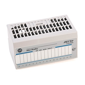
Use the removable label to note individual designations per Analog I/O Module your application. Indicators Indicators are provided to identify input or output fault conditions, and to show when power is applied to the module. For example, the 1794-IE8H module is shown below. 1794-IE8H Module Type Removable Label... -
Page 20: Data Format Alarm Example
About the FLEX I/O HART Analog Modules Data Format Alarm Example In this example, the normal active data range is 4-20 mA. The alarms are generated in three overlapping bands. PHYSICAL INPUT SIGNAL RANGE 0 mA 4 mA 20 mA 22 mA Underrange Overrange... -
Page 21: Remote Fault Alarm
(high or low) value. The remote fault alarm allows the 1794-IE8H module to work with transmitters like the one just described. You must use the Remote Transmitter Error Up or Down feature, see page 2-2, to configure your application for Remote Fault notification. -
Page 22: Local Fault Alarm
About the FLEX I/O HART Analog Modules Programming the Remote Fault Alarm For the remote fault alarm, you must program the threshold in 0.1 mA steps at any level on the high or low end of input signal range. The remote fault alarm activates if your I/O module receives input signal values of: •... -
Page 23: How To Use The Hart Capabilities
About the FLEX I/O HART Analog Modules Before using the HART capabilities, be sure that: How to Use the HART Capabilities • the I/O module and the associated field device are working properly in the analog 4 to 20 mA mode. •... -
Page 24: Chapter Summary
About the FLEX I/O HART Analog Modules In this chapter, you learned about FLEX I/O analog I/O modules and HART Chapter Summary module capabilities. Move on to Chapter 2 to learn about configurable features on your module. Publication 1794-UM063A-EN-P - March 2006... -
Page 25: What This Chapter Contains
Read this chapter to familiarize yourself with configurable features on the What This Chapter Contains input and output analog modules. For Information On See Page Select Your 1794-IE8H FLEX I/O Analog Input Module’s Operating Features Select Your 1794-OE8H FLEX I/O Analog Output Module’s Operating Features Understand Image Table Mapping and... -
Page 26: Features
For more information on your programming software, see the software user manual. All features of the 1794-IE8H analog input module are independently Select Your 1794-IE8H configurable in two four-channel groups (channel 0 to 3 & channel 4 to 7). -
Page 27: High Low Error Level
Configurable FLEX I/O Analog Module Features When setting the Remote Transmitter Error Up or Down feature in your programming software, set this feature’s bit to 0 to select up. Set the bit to 1 to select down. For more information on the Remote Fault Alarm, see page 1-5. For more information on the Local Fault Alarm, see page 1-6. -
Page 28: Data Format
• 12 Formats are available • Default format is 0 to 20 mA • The data format selected interprets input readings and returns them to the PLC Table 2.3 1794-IE8H Data Formats Data Format Resolution Input Module Data Processing... - Page 29 Configurable FLEX I/O Analog Module Features Table 2.3 1794-IE8H Data Formats Data Format Resolution Input Module Data Processing Data Table Value Count Error Format Range (Interpretation) per mA Steps 4…20 mA 0.16% of 2…22 mA -1250 … +11250 With input-4...
- Page 30 Configurable FLEX I/O Analog Module Features Data Formats and Error Ranges PHYSICAL INPUT SIGNAL RANGE 0 mA 20 mA 22 mA Normal Signal Range Overrange Remote Fault Local Format 0 0.00 mA 20.00 mA 22.00 mA Fault Format 1 0.00% 100.00% 110.00% Programmable...
-
Page 31: Select Your 1794-Oe8H Flex I/O Analog Output Module's
Configurable FLEX I/O Analog Module Features All features of the 1794-OE8H analog output module are independently Select Your 1794-OE8H configurable in two four-channel groups (channel 0 to 3 and channel 4 to 7). FLEX I/O Analog Output Module’s Operating The default selection value for all parameters is 0. IMPORTANT Features Local Fault Mode... -
Page 32: Analog Digital State
Configurable FLEX I/O Analog Module Features Analog Digital State You can configure your FLEX I/O analog output modules to work in an analog mode or digital mode using the Analog Digital State feature. Depending on which state you choose for your application, additional parameters (see the descriptions of Analog Fault State and Digital Fault State on page 2-8) must be configured for your module to react to fault conditions. -
Page 33: Data Format
Configurable FLEX I/O Analog Module Features Data Format You must choose a module data format in your user program. See 1794-OE8H Data Formats on page 2-10 for an explanation of each bit. Data Formats 2, 5, 6, 8, 9, 10, 12 and 15 are not assigned. When choosing a data format, remember the following: •... - Page 34 2-10 Configurable FLEX I/O Analog Module Features Table 2.4 1794-OE8H Data Formats Data Format Resolution Full Module Data Processing Data Table Value Count Analog Fault Format Output (Interpretation) per mA State Range mA as 0.1% of 0…22 mA 0…22000 1000 Min=0 mA datatable Output =...
-
Page 35: Fault Alarm
Configurable FLEX I/O Analog Module Features 2-11 Table 2.4 1794-OE8H Data Formats Data Format Resolution Full Module Data Processing Data Table Value Count Analog Fault Format Output (Interpretation) per mA State Range Not Assigned D/A count 0.28% of 0…22 mA 0…8000 Min=0 mA datatable... -
Page 36: Understand Image Table Mapping And Bit/Word Descriptions
Complete definitions of these feature documented below can be found in Chapter 2. Table 2.5 Bit/Word Descriptions Bit(s) Location Definition 1794-IE8H Input and output maps Channel 1794-OE8H Input and output maps Ovr Alm 1794-IE8H Input map Overrange Alarm... -
Page 37: Analog Input Module (1794-Ie8H) Image Table Mapping
Configurable FLEX I/O Analog Module Features 2-13 Analog Input Module (1794-IE8H) Image Table Mapping Table 2.6 Input Map (Read Words) → ↓ Word Channel 0 Input Data Channel 1 Input Data Channel 2 Input Data Channel 3 Input Data Channel 4 Input Data... -
Page 38: Bit/Word Description For The Analog Input Module
U/D = up/down Flt Md = Fault Module Sqrt = Square Root Bit/Word Description for the Analog Input Module (1794-IE8H) Table 2.8 Fault Mode - Write Words 0 and 1 Word 0 Bit 00 Fault enable for channels 0…3 Word 1 Bit 00 Fault enable for channels 4…7... - Page 39 Configurable FLEX I/O Analog Module Features 2-15 Table 2.11 Data Format - Write Words 0 and 1 Bits Description Word 0 04 03 02 01 Data format for channels 0…3 Word 1 04 03 02 01 Data format for channels 4…7 0…22 mA, with error steps (default) 0…22 mA = 0…110%, with error steps 0…22 mA = 0…104.8%, square root, with error steps...
-
Page 40: Analog Output Module (1794-Oe8H) Image Table Mapping
2-16 Configurable FLEX I/O Analog Module Features Analog Output Module (1794-OE8H) Image Table Mapping Table 2.13 Input Map (Read Words) → ↓ Word Reserved Diagnostic Status Reserved Fail Fail Fail Fail Fail Fail Fail Fail ch 7 ch 6 ch 5 ch 4 ch 3 ch 2... - Page 41 Configurable FLEX I/O Analog Module Features 2-17 Table 2.15 Configuration Map (Write Words) → ↓ Word Lo Flt Rese Alg Flt Alg Flt Data Format Data Format rved ch 2…3 ch 0…1 2…3 0…1 2…3 0…1 Alg Flt Alg Flt Data Format Data Format ch 6…7...
- Page 42 2-18 Configurable FLEX I/O Analog Module Features Table 2.16 Data Format Control Data Range Resolution Full Interpretation Data Table Count per Format Range Value 0…20mA 0.1% of 0…22 mA 0…22 mA 0…2000 1000 0…20 mA 0.2% of 0-110% 0…11000 0…20 mA Not Assigned 0.03% of 0…20 mA Unsigned...
-
Page 43: 1794-Ie8H And -Oe8H Extended Configuration Data Table
Configuration Data Table to be sent to the I/O module. For a get attribute single, two words configured as defined in the Extended Configuration Data Table will be returned from the instruction. Table 2.17 1794-IE8H and -OE8H Extended Configuration Data Table → ↓... -
Page 44: Secondary Master Enable (Sme) And Primary Master Inhibit (Pmi)
2-20 Configurable FLEX I/O Analog Module Features Secondary Master Enable (SME) and Primary Master Inhibit (PMI) These two bits control a few module internal functions individually for channels 0 to 7. Table 2.18 SME and PMI Values 1 (Default) Bits 8, 9, 10, 11, 12, 13, 14, 15 0, 1, 2, 3, 4, 5, 6, 7... -
Page 45: Chapter Summary
Configurable FLEX I/O Analog Module Features 2-21 HART Read Back Threshold This bit delivers the percentage value, in steps of 1%, of the threshold for forcing the HART read back indication. The maximum input signal deviation for HART analog modules is 31%. If there is no HART transmitter on the loop or if the loop is not in the transmitter list, the function is switched off internally in the I/O module. - Page 46 2-22 Configurable FLEX I/O Analog Module Features Notes: Publication 1794-UM063A-EN-P - March 2006...
-
Page 47: What This Chapter Contains
Chapter Install Your FLEX I/O Analog Modules Read this chapter to install the input and output analog modules. What This Chapter Contains For Information On See Page Before You Install Your Analog Module Removal and Insertion Under Power Install the Module Connect Wiring to the FLEX I/O HART Analog Modules Ground the Module... -
Page 48: Removal And Insertion Under Power
Install Your FLEX I/O Analog Modules Removal and Insertion These module are designed so you can remove and insert them WARNING Under Power under power. However, take special care when removing or inserting these modules in an active process. I/O attached to any module being removed or inserted can change states due to its input/output signal changing conditions. -
Page 49: Mount On A Din Rail
Install Your FLEX I/O Analog Modules Mount on a DIN Rail Do not remove or replace a terminal base unit when power is ATTENTION ATTENTION applied. Interruption of the flexbus can result in unintended operation or machine motion. Install the Terminal Base Unit 1. - Page 50 Install Your FLEX I/O Analog Modules 41107 Slide the terminal base over tight against the adapter (or proceeding terminal base). Make sure the hook on the terminal base slides under the edge of the adapter (or proceeding terminal base) and the flexbus connector is fully retracted. Do not force the terminal base into the adjacent modules.
-
Page 51: Mount On A Panel Or Wall
Install Your FLEX I/O Analog Modules 6. For specific wiring information, refer to the installation instructions for the module you are installing in this terminal base unit. Terminal assignments are also given later in this chapter, see page 3-8. 7. Repeat the above steps to install the next terminal base unit. 8. - Page 52 Install Your FLEX I/O Analog Modules To install the mounting plate on a wall or panel: 1. Lay out the required points on the wall/panel as shown in the drilling dimension drawing. Drilling Dimensions for Panel/Wall Mounting of FLEX I/O 35.5 58.5 35.5...
-
Page 53: Mount The Analog Modules On The Terminal Base Unit
1794-TB3GS terminal base unit. 1. Rotate keyswitch (1) on terminal base unit (2) clockwise to position 3 for the 1794-IE8H or position 4 for the 1794-OE8H as required for each type of module. Do not change the position of the keyswitch after wiring the terminal base unit. -
Page 54: Wire The Terminal Base Units
Connect Wiring to the Inputs/Outputs FLEX I/O HART Analog Each 1794-IE8H input can be operated from an analog field device signal, and Modules each 1794-OE8H output channel can operate an analog field device. The channels of the 1794-IE8H are electrically connected to each other and have a common plus-line. -
Page 55: Connections For The 1794-Ie8H Hart Analog Input Module On A 1794-Tb3G Terminal Base Unit
Install Your FLEX I/O Analog Modules Connections for the 1794-IE8H HART Analog Input Module on a 1794-TB3G Terminal Base Unit 4 to 20mA 4 to 20mA Xmit Xmit 91 Ω Flexbus 22 Ω 40072 Chassis Chassis Ground Ground -V (COM) - Page 56 6. If continuing common to the next terminal base unit, connect a jumper from terminal 51 (-V common) on this base unit to the -V common terminal on the next terminal base unit. Table 3.2 Wiring Connections for the 1794-IE8H HART Analog Input Module Input Input...
-
Page 57: Connections For The 1794-Oe8H Hart Analog Output Module On A 1794-Tb3G Or 1794-Tb3Gs Terminal Base Unit
Install Your FLEX I/O Analog Modules 3-11 Connections for the 1794-OE8H HART Analog Output Module on a 1794-TB3G or 1794-TB3GS Terminal Base Unit 250 Ω Power Supply 21.6V 4 to 20 mA Valve Flexbus HART Modem 4 to 20 mA 45 Ω... -
Page 58: Ground The Module
3-12 Install Your FLEX I/O Analog Modules 5. If continuing power to the next terminal base unit, connect a jumper from terminal 50 (+V dc) on this base unit to +V dc power terminal on the next terminal base unit. 6. -
Page 59: Chapter Summary
Install Your FLEX I/O Analog Modules 3-13 In this chapter, we told you how to install your input module in an existing Chapter Summary programmable controller system and how to wire to the terminal base units. Move to chapter 4 to learn about input, output and configuration files for the HART analog I/O modules on the ControlNet network. - Page 60 3-14 Install Your FLEX I/O Analog Modules Publication 1794-UM063A-EN-P - March 2006...
-
Page 61: What This Chapter Contains
Chapter Input, Output and Configuration Files for the Analog I/O Modules on the ControlNet Network Read this chapter to familiarize yourself with input, output and configuration What This Chapter Contains files for analog I/O modules on the ControlNet network. For Information On See Page Use Programming Software in Your FLEX I/O Application... -
Page 62: Use Programming Software In Your Flex I/O Application
Input, Output and Configuration Files for the Analog I/O Modules on the ControlNet Network When using FLEX I/O analog modules, you must perform I/O mapping and Use Programming Software configure the ControlNet network before generating configuration data for in Your FLEX I/O Application your I/O modules. -
Page 63: Communication Over The Flex I/O Backplane
Input, Output and Configuration Files for the Analog I/O Modules on the ControlNet Network One 1794-ACNR15/B ControlNet adapter can interface up to eight terminal Communication Over the base units with installed FLEX I/O modules, forming a FLEX I/O system of FLEX I/O Backplane up to eight slots. -
Page 64: Unscheduled Data Transfer
Input, Output and Configuration Files for the Analog I/O Modules on the ControlNet Network Unscheduled Data Transfer Unscheduled operations include: • unscheduled nondiscrete I/O data transfers–through ControlNet I/O Transfer (CIO) instructions. • peer-to-peer messaging–through message (MSG) instructions. • messaging from programming devices. Unscheduled messaging on a ControlNet network is nondeterministic. -
Page 65: Adapter Status Word
Input, Output and Configuration Files for the Analog I/O Modules on the ControlNet Network ControlNet Adapter Read Data Adapter Status Slot 0 Input Data Slot 1 Input Data Network READ Slot 7 Input Data Read Module Module Module Slot 0 Slot 1 Slot 7 Write... -
Page 66: Fault State Data
Input, Output and Configuration Files for the Analog I/O Modules on the ControlNet Network As an example, in a PLC-5 system, the adapter status word bit descriptions are shown in the following table. Table 4.1 Adapter Status Word Bit Descriptions Bit Description Explanation This bit is set (1) when an error is detected in slot position 0. -
Page 67: Device Actions
Input, Output and Configuration Files for the Analog I/O Modules on the ControlNet Network Device actions include: Device Actions • Communication fault behavior • Idle state behavior • Input data behavior upon module removal Communication Fault Behavior You can configure the response to a communication fault for each I/O module in its system. -
Page 68: Chapter Summary
Input, Output and Configuration Files for the Analog I/O Modules on the ControlNet Network In this chapter you learned about input, output and configuration files for the Chapter Summary analog I/O modules on ControlNet. Move to Chapter 5 to learn how to calibrate your module. -
Page 69: What This Chapter Contains
Analog I/O Module Tools and Equipment 1794-IE8H Calibration Features 1794-IE8H Calibration Command Structure 1794-IE8H Calibration Command Byte 1794-IE8H Calibration Item Byte Channel-Mask 1794-IE8H Calibration with Offset and Gain 5-10 1794-OE8H Calibration Features 5-11 1794-OE8H Calibration Command Byte 5-12 1794-OE8H Calibration Item Byte... -
Page 70: Tools And Equipment
Industrial Terminal and Programming terminal for A-B family processors Interconnect Cable The following features are unique to the 1794-IE8H module: 1794-IE8H Calibration Features • There are two different values per channel that need to be calibrated: gain and offset at room temperature (25 °C). -
Page 71: 1794-Ie8H Calibration Command Structure
Calibrate Your Module Calibration of the HART I/O module is performed using data structures and 1794-IE8H Calibration MSG Ladder-logic instructions. The MSG instruction sends the data structure Command Structure to a dedicated attribute in the FLEX HART I/O module and the associated response is read from the same attribute. -
Page 72: 1794-Ie8H Calibration Command Byte
= Last Written Command Executed/idle = Error Occurred During Execution of Last Command, Command Aborted = Last Written Command Pending = Reserved Table 5.3 1794-IE8H Calibration Command List Calibration Command (Decimal) Function Bits 0…5 Reserved Calibrate offset at 25 °C Calibrate gain at 25 °C... - Page 73 Calibrate Your Module Table 5.4 1794-IE8H Interpretation of Command Data Structure Content During Write Access Command Byte Item Byte Data1 Byte Data2 Byte Reserved (Binary) Command Bits 0…5 (Decimal) Calibrate offset at 25 °C Channel-Mask Reserved Reserved Calibrate gain at 25 °C 3…7...
- Page 74 Calibrate Your Module Table 5.5 1794-IE8H Interpretation of Calibration Data Structure Content During Read Access (Idle Status) Command Byte Item Byte Data1 Data2 Byte Byte Status (Binary) Command Bits 0…5 (Decimal) Idle Nothing is done. The state after power on.
- Page 75 Calibrate Your Module Table 5.7 1794-IE8H Interpretation of Calibration Data Structure Content During Read Access (Pending Status) Command Byte Item Byte Data1 Data2 Byte Byte Status (Binary) Command Bits 0…5 (Decimal) Pending Calibration of offset at 25 °C is in process...
-
Page 76: 1794-Ie8H Calibration Item Byte Channel-Mask
The LSB corresponds to channel 0, for example, 0x03 > channel 0 and 1 have to be calibrated. Calibrate Channel 0 Calibrate Channel 1 Calibrate Channel 7 Table 5.8 1794-IE8H Calibration Item Byte Value Identifier List Identifier (Decimal) Value Access Rule Offset channel 0 Read/write …... - Page 77 Calibrate Your Module 1794-IE8H Calibration Item Byte Value Identifier 48 (Status Mask Offset) Each bit of the lower byte of this word corresponds to one channel. A logical 1 within the lower byte of the words means that this channel is calibrated according to offset at room temperature.
-
Page 78: 1794-Ie8H Calibration With Offset And Gain
5-10 Calibrate Your Module 1794-IE8H Calibration with Offset and Gain You must calibrate the offset from a channel before gain is calibrated at the same channel, because the gain value depends on the offset value. During the calibration of offset, the corresponding gain value is declared invalid. Before all values are calibrated, there is a calibration error displayed within the Real Time Data in the diagnostic status. -
Page 79: 1794-Oe8H Calibration Features
Calibrate Your Module 5-11 The following features are unique to the 1794-OE8H module: 1794-OE8H Calibration Features • There are six values per channel that the I/O module uses to calculate the corresponding calibration values (offset and gain). – Min Scale DAC at 1500 about 1 mA –... -
Page 80: 1794-Oe8H Calibration Command Byte
5-12 Calibrate Your Module 1794-OE8H Calibration Command Byte The Calibration command byte uses the following format to write to the module: Calibration Command Reserved (10 Must Be Written) The Calibration command byte uses the following format to read from the module: Last Calibration Command Mirrored Back Status of last written Calibration command... -
Page 81: Channel-Mask
Calibrate Your Module 5-13 Table 5.9 1794-OE8H Calibration Command List Calibration Command (Decimal) Function Bits 0…5 Reserved Calibration command min scale Calibration command max scale Write measured min scale value (Current, uA) Write measured min scale value (Voltage, uV) Write measured max scale value (Current, uA) Write measured max scale value (Voltage, uV) Reserved Set all calibration values to default... - Page 82 5-14 Calibrate Your Module Table 5.11 1794-OE8H Interpretation of Calibration Data Structure Content During Read Access (Idle Status) Command Byte Item Byte Data1 Byte Data2 Byte Status (Binary) Command Bits 0…5 (Decimal) Idle Nothing is done. The state after power on. The min scale value is supported at the outputs according Channel-mask to channel-mask...
- Page 83 Calibrate Your Module 5-15 Table 5.12 1794-OE8H Interpretation of Calibration Data Structure Content During Read Access (Error Status) Command Byte Item Byte Data1 Byte Data2 Byte Status (Binary) Command Bits 0…5 (Decimal) Error The written min scale value of Current was not Channel-mask Value Value...
- Page 84 5-16 Calibrate Your Module Table 5.13 1794-OE8H Interpretation of Calibration Data Structure Content During Read Access (Pending Status) Command Byte Item Byte Data1 Byte Data2 Byte Status (Binary) Command Bits 0…5 (Decimal) Pending Calibration command number 1 is in interpretation Channel-mask Calibration command number 2 is in interpretation The written min scale value of Current is in...
-
Page 85: 1794-Oe8H Calibration Item Byte Channel-Mask
Calibrate Your Module 5-17 1794-OE8H Calibration Item Byte Channel-Mask The Calibration item byte channel-mask uses each bit of the byte to correspond to one channel: where 1 is calibrate this channel and 0 is do not calibrate this channel. The LSB corresponds to channel 0, e.g., 0x03 > channel 0 and 1 have to be calibrated. -
Page 86: 1794-Oe8H Calibration Flowchart Procedure
5-18 Calibrate Your Module 1794-OE8H Calibration Item Byte Value Identifier 48 (Status Mask Calibration) Each bit of the lower byte of this word corresponds to one channel. A logical 1 within the lower byte of the words means that this channel is completely calibrated. - Page 87 Calibrate Your Module 5-19 Start of calibration Measurement equipment is connected to channel x Write calibration command 1 or 2 to I/O module calibration calibration Abort by status status power-cycle idle? erroneous? The voltage is measured Write voltage Write voltage value to I/O value to I/O module with...
- Page 88 5-20 Calibrate Your Module Notes: Publication 1794-UM063A-EN-P - March 2006...
-
Page 89: What This Chapter Contains
Chapter Summary Status Indicators 1794-IE8H Module The 1794-IE8H module has one power indicator that is on when power is applied to the module and one status indicator for each input. A = Status indicators B = Insertable labels for writing individual input... -
Page 90: 1794-Oe8H Module
The 1794-OE8H module has one power indicator that is on when power is applied to the module, and one status indicator for each input. A = Status indicators B = Insertable labels for writing individual input Allen-Bradley 1794- OE8H 8 CHANNEL ANALOG OUTPUT designations... -
Page 91: 1794-Ie8H Hart Input Module
Appendix Specifications 1794-IE8H HART Input Refer to publication 1794-IN108 for complete specifications for the 1794-IE8H HART Input module. Module 1794-OE8H HART Refer to publication 1794-IN109 for complete specifications for the 1794-OE8H HART Output module. Output Module Publication 1794-UM063A-EN-P - March 2006... - Page 92 Specifications Notes: Publication 1794-UM063A-EN-P - March 2006...
-
Page 93: What This Appendix Contains
Appendix FLEX I/O HART Module Commands Read this appendix to learn the module commands to and from FLEX I/O What This Appendix HART modules. Contains HART field communications protocol is widely accepted in the industry as the Protocol Overview standard for digitally enhanced 4 to 20 mA communication with smart field instruments. -
Page 94: Universal Commands
FLEX I/O HART Module Commands Universal Commands Table B.1 Universal HART Module Commands Command Action Meaning Read Read unique device Twelve-byte device identifiers are identification given in the response Read HART variables (process Commands are only supported for values) compatibility purposes and are without any meaning The transmitters, i.e., the SCAN function, have the following... -
Page 95: Common Practice Commands
FLEX I/O HART Module Commands Common Practice Commands Table B.2 Common Practice HART Module Commands Command Action Meaning Write Reset configuration changed Delete status information flag Perform device self-test Performs the device self-test similar to turning on the power supply If no error occurs, the malfunction status message is deleted (if it had been set) - Page 96 FLEX I/O HART Module Commands Table B.3 Device-Specific HART Module Commands Command Action Meaning Read Read static data of transmitters For the given long frame addresses, the function returns the following transmitter data: • Current loop number, 0…15 • Polling address •...
- Page 97 FLEX I/O HART Module Commands Table B.3 Device-Specific HART Module Commands Command Action Meaning Write Delete the number of command Reset the communication statistic requests and errors of the transmitters Read Read counts of host Communication statistic communications concerning the multiplexer Write Reset counts of host Reset the communication statistic...
- Page 98 FLEX I/O HART Module Commands Table B.3 Device-Specific HART Module Commands Command Action Meaning Read Read special SCAN parameters The current special parameters and, if available, the transmitter data are returned for the given loop. These are: • Loop number •...
-
Page 99: What This Appendix Contains
Appendix Additional HART Protocol Information This appendix discusses the HART protocol and provides references for What This Appendix additional information about the protocol. The appendix provides: Contains • HART protocol background information • Command practice command sets • Extended command sets •... -
Page 100: Transaction Procedure
Additional HART Protocol Information Transaction Procedure HART is a half-duplex protocol; after completion of each message, the FSK carrier signal must be switched off, to allow the other station to transmit. The carrier control timing rules state that the carrier should be turned on not more than 5 bit times before the start of the message (that is, the preamble) and turned off not more than 5 bit times after the end of the last byte of the message (the checksum). - Page 101 Additional HART Protocol Information Preamble The preamble is a number of hexadecimal FF characters that precede all frames sent to the HART field device. The size depends on the field devices being used, but it can be from 2 to 32 hexadecimal. The default is 10. The Smart Transmitter Interface inserts the required preamble before each packet or frame transmission to the HART device.
- Page 102 Additional HART Protocol Information HART Command This one-byte field specifies the HART command that is to be sent by the Smart Transmitter Interface to the field device. Many commands are device dependent. Consult the documentation provided with your field device for details about the commands supported.
- Page 103 Additional HART Protocol Information Response Code This two-byte code contains the HART field device status as sent by that device. Field devices detecting a communications error set the most significant bit, bit 7, of the first byte and identify the error in the other seven bits. If the last message was received without error, the field device will clear bit 7 and return a device-dependent response in the other seven bits.
- Page 104 Additional HART Protocol Information Table C.4 HART Field Device Error Codes Error Code Description Field Device Malfunction An internal hardware error or failure has been detected by the HART field device. Configuration Changed A write or set command has been executed by the HART field device.
-
Page 105: Universal Commands
Additional HART Protocol Information Universal Commands Table C.5 Universal Commands Command Data in Command Data in Reply Function Byte Data Type Byte Data Type Read unique — None — 254 (expansion) — identifier Manufacturer identification code Manufacturer device type code Number of preambles required Universal command... - Page 106 Additional HART Protocol Information Table C.5 Universal Commands Command Data in Command Data in Reply Function Byte Data Type Byte Data Type Read unique 0…5 0…11 As Command 0 — identifier associated with tag Read message — None — 0…23 Message (32 characters) Read tag descriptor,...
-
Page 107: Common Practice Commands
Additional HART Protocol Information Common Practice Commands Table C.6 Common Practice Commands Command Data in Command Data in Reply Function Byte Data Byte Data Type Type Read transmitter — — Transmitter variable — None variables code for slot 0 Units code for slot 0 2…5 Variable for slot 0 Transmitter variable... - Page 108 C-10 Additional HART Protocol Information Table C.6 Common Practice Commands Command Data in Command Data in Reply Function Byte Data Byte Data Type Type Set (trim) PV zero — None — — None — Write PV units PV units code —...
- Page 109 Additional HART Protocol Information C-11 Table C.6 Common Practice Commands Command Data in Command Data in Reply Function Byte Data Byte Data Type Type Read transmitter — Transmitter variable — Transmitter variable — variable information code code 1…3 Transmitter variable sensor serial number Transmitter variable limit units code...
- Page 110 C-12 Additional HART Protocol Information Table C.6 Common Practice Commands Command Data in Command Data in Reply Function Byte Data Byte Data Type Type Read dynamic — None — PV analog output units — variables and PV code analog output 1…4 PV analog output level (F) PV units code...
- Page 111 Additional HART Protocol Information C-13 Table C.6 Common Practice Commands Command Data in Command Data in Reply Function Byte Data Byte Data Type Type Read analog output Analog output number — Analog output number — information code code Analog output alarm select code Analog output transfer function code...
- Page 112 C-14 Additional HART Protocol Information Table C.6 Common Practice Commands Command Data in Command Data in Reply Function Byte Data Byte Data Type Type Trim analog output Analog output number — — As in command — gain code Analog output units code 2…5 Externally measured...
- Page 113 Additional HART Protocol Information C-15 Table C.6 Common Practice Commands Command Data in Command Data in Reply Function Byte Data Byte Data Type Type Read all dynamic — None — PV units code — variables 1…4 PV value SV units code —...
- Page 114 C-16 Additional HART Protocol Information Notes: Publication 1794-UM063A-EN-P - March 2006...
-
Page 115: What This Appendix Contains
Appendix FLEX I/O HART Modules Network Messaging This appendix discusses: What This Appendix Contains • How to communicate with the FLEX I/O HART modules via the MSG or CIO instruction • The differences between Attributes and Assembly Indexes • Enhancements to the HART frame The messaging between the processor and the HART I/O module is handled Communication via MSG or CIO instructions, depending on the processor type. - Page 116 FLEX I/O HART Modules Network Messaging Table D.1 Attribute Values Attribute (Hex) Assembly Length (Byte) Read/Write Description Index HART Common Group Extended configuration Calibration Host Access Group 1 Grant for Group 1 access Response Status Information Group 1 Status of loops Hart request/Response buffer Group 1 Hart request/Response buffer Group 1 Hart request/Response buffer Group 1...
-
Page 117: Differences Between Attributes And Assembly Indexes
FLEX I/O HART Modules Network Messaging The two Host Access Groups on the module let two different hosts Differences Between communicate at the same time to the module and its associated field devices. Attributes and Assembly The Attribute used by MSG or CIO instructions send the attribute number to Indexes the adapter module. - Page 118 FLEX I/O HART Modules Network Messaging The response from the HART command is reformatted to add this handle and to add additional status information. Figure D.1 Response from the HART Command Status Start Address Command Byte Count (Response Data Checksum (6 Bytes) Character Code)
- Page 119 FLEX I/O HART Modules Network Messaging • Handle This indicates the Handle of the response. • Response Error In the following table, values 6 through 10 are communication errors. Value Meaning No error Timeout on HART loop Invalid long frame address Locked Request overflow Response not available...
-
Page 120: Hart Frame Enhancements
FLEX I/O HART Modules Network Messaging • Loop status available New loop status is available in Status of Loops assembly. • Lock To protect against a second HART host communicating to modules, the HART_lock bit is set in the Group for Group assembly. Value Meaning Not locked... -
Page 121: What This Appendix Contains
Appendix Configure the 1794-IE8H Module in RSLogix 5000 Software Over the ControlNet Network This appendix provides the information needed to configure the 1794-IE8H What This Appendix analog input module in RSLogix 5000 software over the ControlNet network Contains using version 13 or earlier and the generic profile. -
Page 122: Configuration
Configure the 1794-IE8H Module in RSLogix 5000 Software Over the ControlNet Network Refer to the following tables for configuration information. Configuration Fault Mode Channel Bits 0…3 [Adapter Name]:[Slot]:C.Data[0].0 4…7 [Adapter Name]:[Slot]:C.Data[1].0 Fault Mode Bit 0 Disabled Enabled Data Format Control... - Page 123 Configure the 1794-IE8H Module in RSLogix 5000 Software Over the ControlNet Network Data Format Bits Range Resolution Full Range Interpretation Data Value Table Count per mA 0…20 mA 0.1% of 0…20 mA 0…22 mA 0…22 mA 0…22000 1000 0…20 mA 0.2% of 0…20 mA...
-
Page 124: Filter Cutoff
Configure the 1794-IE8H Module in RSLogix 5000 Software Over the ControlNet Network Filter Cutoff The generic profile sets all of the filter bits to 0, which is an invalid value. You must set these bits to a valid value or you will get a diagnostic error value of 2. -
Page 125: Up/Down Bit
Configure the 1794-IE8H Module in RSLogix 5000 Software Over the ControlNet Network Up/Down Bit Channel Bits 0…3 [Adapter Name]:[Slot]:C.Data[0].8 4…7 [Adapter Name]:[Slot]:C.Data[1].8 Up/Down Bit Description Down High and Low Error Level Channel Bits 0…3 [Adapter Name]:[Slot]:C.Data[0].9 [Adapter Name]:[Slot]:C.Data[0].10 [Adapter Name]:[Slot]:C.Data[0].11 [Adapter Name]:[Slot]:C.Data[0].12... - Page 126 Configure the 1794-IE8H Module in RSLogix 5000 Software Over the ControlNet Network High and Low Error Bits Description Disabled 0.1 mA 0.2 mA 0.3 mA 0.4 mA 0.5 mA 0.6 mA 0.7 mA 0.8 mA 0.9 mA 1.0 mA 1.1 mA 1.2 mA...
-
Page 127: Square Root Threshold
Configure the 1794-IE8H Module in RSLogix 5000 Software Over the ControlNet Network Square Root Threshold Bits [Adapter Name]:[Slot]:C.Data[1].14 [Adapter Name]:[Slot]:C.Data[1].15 Range Disabled Input Analog Input Data Channel Words [Adapter Name]:[Slot]:I.Data[0] [Adapter Name]:[Slot]:I.Data[1] [Adapter Name]:[Slot]:I.Data[2] [Adapter Name]:[Slot]:I.Data[3] [Adapter Name]:[Slot]:I.Data[4] [Adapter Name]:[Slot]:I.Data[5] [Adapter Name]:[Slot]:I.Data[6]... -
Page 128: Overrange Alarm
Configure the 1794-IE8H Module in RSLogix 5000 Software Over the ControlNet Network Overrange Alarm Channel Bits [Adapter Name]:[Slot]:I.Data[8].8 [Adapter Name]:[Slot]:I.Data[8].9 [Adapter Name]:[Slot]:I.Data[8].10 [Adapter Name]:[Slot]:I.Data[8].11 [Adapter Name]:[Slot]:I.Data[8].12 [Adapter Name]:[Slot]:I.Data[8].13 [Adapter Name]:[Slot]:I.Data[8].14 [Adapter Name]:[Slot]:I.Data[8].15 Local Fault Channel Bits [Adapter Name]:[Slot]:I.Data[9].0 [Adapter Name]:[Slot]:I.Data[9].1 [Adapter Name]:[Slot]:I.Data[9].2... -
Page 129: Diagnostic Status
Configure the 1794-IE8H Module in RSLogix 5000 Software Over the ControlNet Network Diagnostic Status Bits [Adapter Name]:[Slot]:I.Data[10].0 [Adapter Name]:[Slot]:I.Data[10].1 [Adapter Name]:[Slot]:I.Data[10].2 [Adapter Name]:[Slot]:I.Data[10].3 Diagnostic Description Bit 3 Bit 2 Bit 1 Bit 0 Normal Calibration Failure Configuration Failure Message Failure... - Page 130 E-10 Configure the 1794-IE8H Module in RSLogix 5000 Software Over the ControlNet Network Publication 1794-UM063A-EN-P - March 2006...
-
Page 131: What This Appendix Contains
Appendix Configure the 1794-OE8H Module in RSLogix5000 Software Over the ControlNet Network This appendix provides the information needed to configure the 1794-OE8H What This Appendix analog output module in RSLogix 5000 software over the ControlNet network Contains using version 13 or earlier and the generic profile. Make sure that your Comm-Format is set to Data - INT. -
Page 132: Data Format Control
Configure the 1794-OE8H Module in RSLogix5000 Software Over the ControlNet Network Refer to the following tables for configuration information. Configuration Data Format Control Channel Bits 0 and 1 [Adapter Name]:[Slot]:C.Data[0].0 [Adapter Name]:[Slot]:C.Data[0].1 [Adapter Name]:[Slot]:C.Data[0].2 [Adapter Name]:[Slot]:C.Data[0].3 2 and 3 [Adapter Name]:[Slot]:C.Data[0].4 [Adapter Name]:[Slot]:C.Data[0].5 [Adapter Name]:[Slot]:C.Data[0].6 [Adapter Name]:[Slot]:C.Data[0].7... - Page 133 Configure the 1794-OE8H Module in RSLogix5000 Software Over the ControlNet Network Data Format Bits Range Resolution Full Range Interpretation Data Value Table Count per mA 0…20 mA 0.1% of 0…20 mA 0…22 mA 0…22 mA 0…22000 1000 0…20 mA 0.2% of 0…20 mA 0…22 mA 0…110% 0…11000...
-
Page 134: Analog Fault State
Configure the 1794-OE8H Module in RSLogix5000 Software Over the ControlNet Network Analog Fault State Analog Fault State for Bits Channel [Adapter Name]:[Slot]:C.Data[3] [Adapter Name]:[Slot]:C.Data[4] [Adapter Name]:[Slot]:C.Data[5] [Adapter Name]:[Slot]:C.Data[6] [Adapter Name]:[Slot]:C.Data[7] [Adapter Name]:[Slot]:C.Data[8] [Adapter Name]:[Slot]:C.Data[9] [Adapter Name]:[Slot]:C.Data[10] Bits 9 or 11 Bits 8 or 10 Min Value of Data Range Max Value of Data Range... -
Page 135: Latch Retry Mode
Configure the 1794-OE8H Module in RSLogix5000 Software Over the ControlNet Network Latch Retry Mode Channel Bits 0…3 [Adapter Name]:[Slot]:C.Data[1].14 4…7 [Adapter Name]:[Slot]:C.Data[1].15 Retry Latch Analog/Digital Mode Channel Bits [Adapter Name]:[Slot]:C.Data[2].0 [Adapter Name]:[Slot]:C.Data[2].1 [Adapter Name]:[Slot]:C.Data[2].2 [Adapter Name]:[Slot]:C.Data[2].3 [Adapter Name]:[Slot]:C.Data[2].4 [Adapter Name]:[Slot]:C.Data[2].5 [Adapter Name]:[Slot]:C.Data[2].6 [Adapter Name]:[Slot]:C.Data[2].7 Analog... -
Page 136: Analog Fault State Values
Configure the 1794-OE8H Module in RSLogix5000 Software Over the ControlNet Network Analog Fault State Values Channel Bits [Adapter Name]:[Slot]:C.Data[3] [Adapter Name]:[Slot]:C.Data[4] [Adapter Name]:[Slot]:C.Data[5] [Adapter Name]:[Slot]:C.Data[6] [Adapter Name]:[Slot]:C.Data[7] [Adapter Name]:[Slot]:C.Data[8] [Adapter Name]:[Slot]:C.Data[9] [Adapter Name]:[Slot]:C.Data[10] Refer to the following tables for output information. Output Digital Output Data Channel... -
Page 137: Analog Output Data
Configure the 1794-OE8H Module in RSLogix5000 Software Over the ControlNet Network Analog Output Data Channel Bits [Adapter Name]:[Slot]:O.Data[1] [Adapter Name]:[Slot]:O.Data[2] [Adapter Name]:[Slot]:O.Data[3] [Adapter Name]:[Slot] O.Data[4] [Adapter Name]:[Slot]:O.Data[5] [Adapter Name]:[Slot]:O.Data[6] [Adapter Name]:[Slot]:O.Data[7] [Adapter Name]:[Slot]:O.Data[8] Refer to the following tables for input information. Input Diagnostic Status Data Diagnostic Description... -
Page 138: Fault Alarm
Configure the 1794-OE8H Module in RSLogix5000 Software Over the ControlNet Network Fault Alarm Channel Bits [Adapter Name]:[Slot]:I.Data[0].8 [Adapter Name]:[Slot]:I.Data[0].9 [Adapter Name]:[Slot]:I.Data[0].10 [Adapter Name]:[Slot]:I.Data[0].11 [Adapter Name]:[Slot]:I.Data[0].12 [Adapter Name]:[Slot]:I.Data[0].13 [Adapter Name]:[Slot]:I.Data[0].14 [Adapter Name]:[Slot]:I.Data[0].15 HART Failure Channel Bits [Adapter Name]:[Slot]:I.Data[2].0 [Adapter Name]:[Slot]:I.Data[2].1 [Adapter Name]:[Slot]:I.Data[2].2 [Adapter Name]:[Slot]:I.Data[2].3 [Adapter Name]:[Slot]:I.Data[2].4 [Adapter Name]:[Slot]:I.Data[2].5... -
Page 139: Hart Communication
Configure the 1794-OE8H Module in RSLogix5000 Software Over the ControlNet Network HART Communication Channel Bits [Adapter Name]:[Slot]:I.Data[3].0 [Adapter Name]:[Slot]:I.Data[3].1 [Adapter Name]:[Slot]:I.Data[3].2 [Adapter Name]:[Slot]:I.Data[3].3 [Adapter Name]:[Slot]:I.Data[3].4 [Adapter Name]:[Slot]:I.Data[3].5 [Adapter Name]:[Slot]:I.Data[3].6 [Adapter Name]:[Slot]:I.Data[3].7 HART Transmitter Channel Bits [Adapter Name]:[Slot]:I.Data[3].8 [Adapter Name]:[Slot]:I.Data[3].9 [Adapter Name]:[Slot]:I.Data[3].10 [Adapter Name]:[Slot]:I.Data[3].11 [Adapter Name]:[Slot]:I.Data[3].12 [Adapter Name]:[Slot]:I.Data[3].13... - Page 140 F-10 Configure the 1794-OE8H Module in RSLogix5000 Software Over the ControlNet Network Publication 1794-UM063A-EN-P - March 2006...
- Page 141 ___No, there is no need to contact me ___Yes, please call me ___Yes, please email me at _______________________ ___Yes, please contact me via _____________________ Return this form to: Rockwell Automation Technical Communications, 1 Allen-Bradley Dr., Mayfield Hts., OH 44124-9705 Fax: 440-646-3525 Email: [email protected] Publication CIG-CO521C-EN-P- May 2003...
- Page 142 PLEASE FASTEN HERE (DO NOT STAPLE) Other Comments PLEASE FOLD HERE NO POSTAGE NECESSARY IF MAILED IN THE UNITED STATES BUSINESS REPLY MAIL FIRST-CLASS MAIL PERMIT NO. 18235 CLEVELAND OH POSTAGE WILL BE PAID BY THE ADDRESSEE 1 ALLEN-BRADLEY DR MAYFIELD HEIGHTS OH 44124-9705...
-
Page 143: Index
Index Alarms High Low Error Level 1794-IE8 module 1794-IE8 module 1-3, 1-6 local fault 1-3, 1-4 overrange programming remote fault 1-3, 1-5 Idle State Behavior remote fault 2-12 1-3, 1-4 Image Table Mapping underrange 2-14 using fault mode with local fault 1794-IE8 bit/word descriptions 2-13 alarm... - Page 144 Index module indicators module repair Remote Transmitter Error Up or Down Two-Wire Transmitter Devices 1794-IE8 module connecting to the 1794-IE8 module Removal and Insertion Under Power (RIUP) Unscheduled Data-Transfer over the FLEX Ex backplane Scheduled Data-Transfer over the FLEX Ex backplane Specifications 1794-IE8 module Wall/Panel Mounting...
-
Page 146: Rockwell Automation Support
Rockwell Automation provides technical information on the Web to assist you in using Rockwell Automation our products. At http://support.rockwellautomation.com, you can find technical Support manuals, a knowledge base of FAQs, technical and application notes, sample code and links to software service packs, and a MySupport feature that you can customize to make the best use of these tools.