beautypg.com
Manuals
Brands
Allen-Bradley Manuals
Control Unit
1794-OE8H
Allen-Bradley 1794-OE8H Manuals
Manuals and User Guides for Allen-Bradley 1794-OE8H. We have
1
Allen-Bradley 1794-OE8H manual available for free PDF download: User Manual
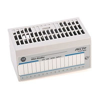
Allen-Bradley 1794-OE8H User Manual (146 pages)
FLEX I/O HART Analog Modules
Brand:
Allen-Bradley
| Category:
Control Unit
| Size: 2.14 MB
Table of Contents
Important User Information
2
North American Hazardous Location Approval
4
European Hazardous Location Approval
5
Table of Contents
7
About the Vocabulary
13
What this Manual Contains
13
Who Should Read this Manual
13
Why Read this Manual
13
For Additional Information
14
Chapter 1
17
Controllers
17
Events Following Power-Up
18
How FLEX I/O Analog Modules Communicate with Programmable
17
What the FLEX I/O Analog I/O Modules Do
17
What this Chapter Contains
17
Physical Features of Your Analog I/O Module
19
Indicators
19
Use Alarms on the 1794-IE8H Module
19
Data Format Alarm Example
20
Overrange Alarm
20
Underrange Alarm
20
Remote Fault Alarm
21
Local Fault Alarm
22
HART Implementation Overview
23
How to Use the HART Capabilities
23
Chapter Summary
24
Chapter 2
25
Select Your 1794-IE8H FLEX I/O Analog Input Module's Operating
25
What this Chapter Contains
25
Features
26
Fault Mode
26
Remote Transmitter Error up or down
26
High Low Error Level
27
Input Filter Cutoff
27
Data Format
28
Operating Features
31
Local Fault Mode
31
Latch Mode
31
Global Reset
31
Analog Digital State
32
Analog Fault State
32
Analog Fault State Value
32
Digital Fault State
32
Data Format
33
Fault Alarm
35
Select Your 1794-OE8H FLEX I/O Analog Output Module's
31
Understand Image Table Mapping and Bit/Word Descriptions
36
Bit Descriptions
36
Analog Input Module (1794-IE8H) Image Table Mapping
37
Bit/Word Description for the Analog Input Module
38
(1794-Ie8H)
38
Analog Output Module (1794-OE8H) Image Table Mapping
40
1794-IE8H and -OE8H Extended Configuration Data Table
43
Secondary Master Enable (SME) and Primary Master Inhibit (PMI)
44
Chapter Summary
45
Before You Install Your Analog Module
47
Chapter 3
47
What this Chapter Contains
47
Install the Module
48
Mount on a DIN Rail
49
Mount on a Panel or Wall
51
Mount the Analog Modules on the Terminal Base Unit
53
Removal and Insertion under Power
48
Connect Wiring to the FLEX I/O HART Analog Modules
54
Inputs/Outputs
54
Connections for the 1794-IE8H HART Analog Input Module on a 1794-TB3G Terminal Base Unit
55
Connections for the 1794-OE8H HART Analog Output Module on a 1794-TB3G or 1794-TB3GS Terminal Base Unit
57
Wire the Terminal Base Units
54
Ground the Module
58
Chapter Summary
59
What this Chapter Contains
61
About the Controlnet Adapter
62
Chapter 4
62
Use Programming Software in Your FLEX I/O Application
62
Communication over the FLEX I/O Backplane
63
Scheduled Data Transfer
63
Unscheduled Data Transfer
64
Module I/O Mapping
64
I/O Structure
64
Adapter Status Word
65
Fault State Data
66
Device Actions
67
Communication Fault Behavior
67
Idle State Behavior
67
Chapter Summary
68
Chapter 5
69
What this Chapter Contains
69
When and How to Calibrate Your FLEX I/O Analog I/O Module
69
1794-IE8H Calibration Features
70
Tools and Equipment
70
1794-IE8H Calibration Command Structure
71
1794-IE8H Calibration Command Byte
72
1794-IE8H Calibration Item Byte Channel-Mask
76
1794-IE8H Calibration with Offset and Gain
78
1794-OE8H Calibration Features
79
1794-OE8H Calibration Command Byte
80
Channel-Mask
81
1794-OE8H Calibration Item Byte Channel-Mask
85
1794-OE8H Calibration Flowchart Procedure
86
Chapter 6 Status Indicators
89
1794-IE8H Module
89
1794-OE8H Module
90
What this Chapter Contains
89
Chapter Summary
90
Repair
90
1794-IE8H HART Input Module
91
1794-OE8H HART Output Module
91
Appendix A
91
Appendix B
93
Protocol Overview
93
What this Appendix Contains
93
Universal Commands
94
Common Practice Commands
95
Device-Specific Commands
95
Appendix C
99
Transaction Procedure
100
Burst Mode (Not Supported
100
Message Structure
99
Master-Slave Operation
99
Multiple Master Operation
99
What this Appendix Contains
99
Universal Commands
105
Common Practice Commands
107
Appendix D
115
Communication
115
What this Appendix Contains
115
Differences between Attributes and Assembly Indexes
117
HART Frame Enhancements
120
Appendix E
121
Background Information
121
What this Appendix Contains
121
Configuration
122
Fault Mode
122
Filter Cutoff
124
Up/Down Bit
125
High and Low Error Level
125
Square Root Threshold
127
Input
127
Analog Input Data
127
Underrange Alarm
127
Overrange Alarm
128
Local Fault
128
Remote Fault
128
Diagnostic Status
129
Appendix F Background Information
131
Data Format Control
132
Analog Fault State
134
Fault Mode
134
Local Fault Mode
134
What this Appendix Contains
131
Latch Retry Mode
135
Analog/Digital Mode
135
Digital Fault State
135
Analog Fault State Values
136
Output
136
Digital Output Data
136
Global Output Data
136
Analog Output Data
137
Input
137
Diagnostic Status Data
137
HART Rebuild Bit
137
Fault Alarm
138
HART Failure
138
HART Readback
138
HART Communication
139
HART Transmitter
139
Index
143
Rockwell Automation Support
146
Installation Assistance
146
New Product Satisfaction Return
146
Related Products
ALLEN BRADLEY 1794-OB16
Allen-Bradley 1794-OA8K
Allen-Bradley 1794-OA8
Allen-Bradley 1794-OA8I
Allen-Bradley 1794-OA16
Allen-Bradley 1794-OE4 Series B
Allen-Bradley FLEX I/O 1794-OB16P
Allen-Bradley FLEX I/O 1794-OB32P
Allen-Bradley FLEX I/O 1794-OB16
Allen-Bradley FLEX I/O 1794-OV32
Allen-Bradley Categories
Control Unit
Controller
I/O Systems
Power Supply
Switch
More Allen-Bradley Manuals