Quick Links
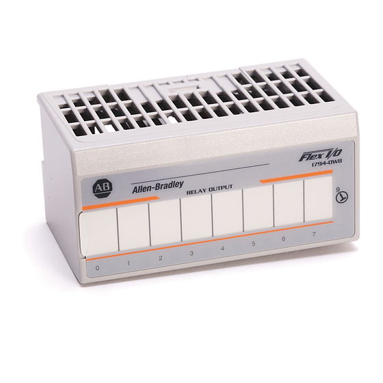
FLEX I/O 8 Relay Output Module
Cat. No. 1794-OW8, 1794-OW8K, 1794-OW8XT
(Modules with a K in the last position of the catalog number are
conformally coated to meet noxious gas requirements of ISA/ANSI-71.040
)
1985 Class G3 Environment.
Important User Information
Solid state equipment has operational characteristics differing from those of electromechanical equipment.
Safety Guidelines for the Application, Installation and Maintenance of Solid State Controls (Publication
SGI-1.1
available from your local Rockwell Automation sales office or online at
http://www.literature.rockwellautomation.com) describes some important differences between solid state
equipment and hard-wired electromechanical devices. Because of this difference, and also because of the
wide variety of uses for solid state equipment, all persons responsible for applying this equipment must
satisfy themselves that each intended application of this equipment is acceptable.
In no event will Rockwell Automation, Inc. be responsible or liable for indirect or consequential damages
resulting from the use or application of this equipment.
The examples and diagrams in this manual are included solely for illustrative purposes. Because of the many
variables and requirements associated with any particular installation, Rockwell Automation, Inc. cannot
assume responsibility or liability for actual use based on the examples and diagrams.
No patent liability is assumed by Rockwell Automation, Inc. with respect to use of information, circuits,
equipment, or software described in this manual.
Reproduction of the contents of this manual, in whole or in part, without written permission of Rockwell
Automation, Inc. is prohibited.
Throughout this manual we use notes to make you aware of safety considerations.
Identifies information about practices or circumstances that can cause an
WARNING
explosion in a hazardous environment, which may lead to personal injury or
death, property damage, or economic loss.
Identifies information that is critical for successful application and understanding
IMPORTANT
of the product.
Identifies information about practices or circumstances that can lead to personal
ATTENTION
injury or death, property damage, or economic loss. Attentions help you identify a
hazard, avoid a hazard, or recognize the consequence
Environment and Enclosure
ATTENTION
This equipment is intended for use in a Pollution Degree 2 industrial
environment, in overvoltage Category II applications (as defined in IEC 60664-1),
at altitudes up to 2000 m (6562 ft) without derating.
This equipment is considered Group 1, Class A industrial equipment according
to IEC/CISPR 11. Without appropriate precautions, there may be difficulties with
electromagnetic compatibility in residential and other environments due to
conducted and radiated disturbances.
This equipment is supplied as open-type equipment. It must be mounted within
an enclosure that is suitably designed for those specific environmental
conditions that will be present and appropriately designed to prevent personal
injury resulting from accessibility to live parts. The enclosure must have suitable
flame-retardant properties to prevent or minimize the spread of flame,
complying with a flame spread rating of 5VA, V2, V1, V0 (or equivalent) if
non-metallic. The interior of the enclosure must be accessible only by the use of
a tool. Subsequent sections of this publication may contain additional
information regarding specific enclosure type ratings that are required to comply
with certain product safety certifications.
In addition to this publication, see:
• Industrial Automation Wiring and Grounding Guidelines, for additional
installation requirements, Allen-Bradley publication 1770-4.1.
• NEMA Standards 250 and IEC 60529, as applicable, for explanations of
the degrees of protection provided by different types of enclosure.
When you insert or remove the module while backplane power is on, an
WARNING
electrical arc can occur. This could cause an explosion in hazardous location
installations. Be sure that power is removed or the area is nonhazardous
before proceeding.
FLEX I/O is grounded through the DIN rail to chassis ground. Use zinc plated
ATTENTION
yellow-chromate steel DIN rail to assure proper grounding. The use of other
DIN rail materials (for example, aluminum or plastic) that can corrode, oxidize,
or are poor conductors, can result in improper or intermittent grounding. Secure
DIN rail to mounting surface approximately every 200 mm (7.8 in.) and use
end-anchors appropriately.
Installation Instructions
Preventing Electrostatic Discharge
ATTENTION
This equipment is sensitive to electrostatic discharge, which can cause internal
damage and affect normal operation. Follow these guidelines when you handle
this equipment:
• Touch a grounded object to discharge potential static.
• Wear an approved grounding wriststrap.
• Do not touch connectors or pins on component boards.
• Do not touch circuit components inside the equipment.
• Use a static-safe workstation, if available.
• Store the equipment in appropriate static-safe packaging when not in
use.
If you connect or disconnect wiring while the field-side power is on, an
WARNING
electrical arc can occur. This could cause an explosion in hazardous location
installations. Be sure that power is removed or the area is nonhazardous
before proceeding.
Personnel responsible for the application of safety-related programmable
ATTENTION
electronic systems (PES) shall be aware of the safety requirements in the
application of the system and shall be trained in using the system.
Do not remove or replace a Terminal Base unit while power is applied.
ATTENTION
Interruption of the backplane can result in unintentional operation or machine
motion.
To comply with the CE Low Voltage Directive (LVD), this equipment must be
ATTENTION
powered from a source compliant with the following:
Safety Extra Low Voltage (SELV) or Protected Extra Low Voltage (PELV).
European Hazardous Location Approval
The 1794-OW8, 1794-OW8K, 1794-OW8XT modules are European Zone 2
approved.
European Zone 2 Certification (The following applies when the product bears the Ex
or EEx Marking)
This equipment is intended for use in potentially explosive atmospheres as defined by European
Union Directive 94/9/EC and has been found to comply with the Essential Health and Safety
Requirements relating to the design and construction of Category 3 equipment intended for use
in potentially explosive atmospheres, given in Annex II to this Directive.
Compliance with the Essential Health and Safety Requirements has been assured by compliance
with EN 60079-15 and EN 60079-0.
Observe the following additional Zone 2 certification requirements.
WARNING
• This equipment is not resistant to sunlight or other sources of UV
radiation.
• This equipment must be installed in an enclosure providing at least IP54
protection when applied in Zone 2 environments.
• This equipment shall be used within its specified ratings defined by
Allen-Bradley.
• Provision shall be made to prevent the rated voltage from being
exceeded by transient disturbances of more than 40% when applied in
Zone 2 environments.
• This equipment must be used only with ATEX certified backplanes.
• Secure any external connections that mate to this equipment by using
screws, sliding latches, threaded connectors, or other means provided
with this product.
• Do not disconnect equipment unless power has been removed or the
area is known to be nonhazardous.

Related Manuals for Allen-Bradley 1794-OW8


Summary of Contents for Allen-Bradley 1794-OW8
- Page 1 European Hazardous Location Approval environment, in overvoltage Category II applications (as defined in IEC 60664-1), The 1794-OW8, 1794-OW8K, 1794-OW8XT modules are European Zone 2 at altitudes up to 2000 m (6562 ft) without derating. This equipment is considered Group 1, Class A industrial equipment according approved.
- Page 2 4. Position the module (4) with its alignment bar (5) aligned with the groove (6) on the terminal base. The 1794-OW8, 1794-OW8K, 1794-OW8XT modules are Hazardous 5. Press firmly and evenly to seat the module in the terminal base Location approved.
- Page 3 This terminal base unit has fuse holders for 5X20mm fuses on each of the 8 generation of electromagnetic noise which could disrupt nearby electrical even-numbered I/O terminals (0 thru 14 - row B). To install or change a equipment, including your 1794 FLEX I/O chassis. Use Allen-Bradley part number fuse: 599-KA04 or 1401-NX1.
- Page 4 IEC 60068-2-30 (Test Db, Unpackaged Damp Heat): If used in European Zone 2 potentially explosive atmospheres: 5…95% noncondensing 1794-OW8 - voltages must be at or below 60V AC or 75V DC; 1794-OW8K - voltages must be at or below all voltage ratings. Vibration...