Hitachi C 10FCH Technical Data And Service Manual
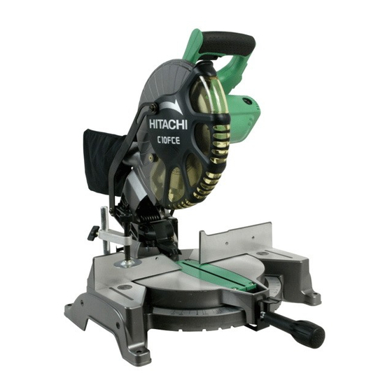
Compound saw
Show thumbs
Also See for C 10FCH:
- Instruction manual (80 pages) ,
- User manual (76 pages) ,
- Handling instructions manual (58 pages)

Related Manuals for Hitachi C 10FCH


Summary of Contents for Hitachi C 10FCH
- Page 1 MODELS C 10FCH C 10FCE Hitachi Power Tools TECHNICAL DATA COMPOUND SAW C 10FCH SERVICE MANUAL C 10FCE LIST Nos. C 10FCH: E936 Apr. 2004 C 10FCE: E937 SPECIFICATIONS AND PARTS ARE SUBJECT TO CHANGE FOR IMPROVEMENT...
- Page 2 REMARK: Throughout this TECHNICAL DATA AND SERVICE MANUAL, a symbol(s) is(are) used in the place of company name(s) and model name(s) of our competitor(s). The symbol(s) utilized here is(are) as follows: WH 9DM2 Competitor Symbol Utilized Company Name Model Name DW703 DEWALT MS1065LZ...
-
Page 3: Table Of Contents
9-1. Bevel Angle Adjustment ........................17 10. PACKING ............................17 11. PRECAUTIONS IN DISASSEMBLY AND REASSEMBLY ............19 11-1. Precautions in Disassembly and Reassembly of the Laser Marker (Only Model C 10FCH) ..19 11-2. Disassembly ............................ 19 11-3. Reassembly ............................ 26 11-4. - Page 4 12. REPAIR GUIDE ..........................37 13. STANDARD REPAIR TIME (UNIT) SCHEDULES ................ 42 Assembly Diagram for C 10FCH ......................44 Assembly Diagram for C 10FCE ......................52...
-
Page 5: Product Name
In addition, the same compound saw without the laser guide system Model C 10FCE is introduced in tandem with the Model C 10FCH. With the new Models C 10FCH and C 10FCE, we aim to enhance the share of the Hitachi compound saw series. -
Page 6: Selling Point Descriptions
The Models C 10FCH and C 10FCE are easier to operate. (4) Lightweight design The Model C 10FCH weighs 12.5 kg and the Model C 10FCE weighs 12 kg. They are the lightest compound saws in this class and easy to carry. - Page 7 C 10FCB (6) Powerful 15 amps motor The Models C 10FCH and C 10FCE are equipped with a 15-ampere motor. The Models C 10FCH and C 10FCE can cut workpieces as quickly as the Model C 10FCB. (7) Thumb actuated positive stops for quick and easy miter adjustment The positive stops are provided to adjust the turn table position for miter cutting more securely than the conventional Model C 10FCB.
-
Page 8: Specifications
• • • • • • • • • • • • • • • Dust bag Vise ass'y 10 mm box wrench 4 mm hex. bar wrench (only Model C 10FCH) Sub fence 255 mm (10") TCT saw blade (60 teeth, Code No. 976472) Optional accessories for normal cutting •... -
Page 9: Comparisons With Similar Products
6. COMPARISONS WITH SIMILAR PRODUCTS Maker/Model HITACHI HITACHI C 10FCB C 10FCH/C 10FCE Item 59 mm x 144 mm 59 mm x 144 mm 59 mm x 144 mm 59 mm x 144 mm (2-5/16" x 5-21/32") (2-5/16" x 5-21/32") (2-5/16"... -
Page 10: Precautions In Sales Promotion
7. PRECAUTIONS IN SALES PROMOTION In the interest of promoting the safest and most efficient use of the Models C 10FCH and C 10FCE Compound Saws by all of our customers, it is very important that at the time of sale the salesperson carefully ensures that the buyer seriously recognizes the importance of the contents of the Instruction Manual, and fully understands the meaning of the precautions listed on the Warning Labels and Caution Labels attached to each machine. - Page 11 (4) Caution label (A) (at the front of the hinge) and caution label (C) (at the front of the base) (only Model C 10FCH) Do not stare into laser beam. If your eye is exposed directly to the laser beam, it can be hurt. Caution label (A) and caution label (C) are adhered to each machine to comply with the standards for the safe use of laser equipment.
-
Page 12: Relative Standards
(2) Laser radiation when open. DO NOT STARE INTO BEAM OR VIEW DIRECTLY WITH OPTICAL INSTRUMENTS. The lilfespan of the laser marker in the Model C 10FCH is about 2,160 hours. (About three years: 4 hours of use/ day x 180 days/year) -
Page 13: Ambient Illuminance And Visibility Of Laser Line (Only Model C 10Fch)
7-5. Ambient illuminance and Visibility of Laser Line (Only Model C 10FCH) The visibility of the laser line on the workpiece changes depending on the brightness of the working environment. Instruct the customer to consider the brightness of the working environment when using the laser marker referring to the following table. -
Page 14: Adjustment And Operation Precautions
8. ADJUSTMENT AND OPERATION PRECAUTIONS 8-1. Position Adjustment of Laser Line (Only Model C 10FCH) Saw blade The laser line is adjusted to the width of the saw blade at the time Workpiece of factory shipment. Depending upon the cutting choice, align the... -
Page 15: How To Use The Vise Assembly
CAUTION: Laser radiation - Do not stare into beam. Laser radiation on work table. Do not stare into beam. If your eye is exposed directly to the laser beam, it can be hurt. Do not dismantle it. Do not give strong impact to the laser marker (main body of tool); otherwise, the position of a laser line can go out of order, resulting in the damage of the laser marker as well as a shortened service life. -
Page 16: Confirmation For Use Of Sub Fence (Standard Accessory)
8-3. Confirmation for Use of Sub Fence (Standard accessory) In the case of press cutting and miter cutting, use the sub Sub fence (standard fence. The sub fence can be installed on the left side of the accessory) guide fence. Insert the rods of the sub fence into the holes 6 mm wing bolt in the guide fence. -
Page 17: Cutting Operation
(4) Press cutting Like the Model C 10FC, the Models C 10FCH and C 10FCE can be used for press cutting of workpieces up to 59 mm x 144 mm (2-1/4" x 5-5/8") in a single operation by simply pushing the saw blade section (head) downward. - Page 18 (7) Compound (miter + bevel) cutting Compound cutting can be accomplished by combining the miter cutting and bevel cutting operations described in paragraphs (4) and (5) above. (For details, please refer to the Instruction Manual.) When the saw blade section (head) is inclined 45û to the left, the table can be turned up to 45û to the right and left. (8) Crown molding cutting This machine can cut two types of crown molding workpieces by combining the miter and bevel cutting operations (for USA).
- Page 19 (1) Setting to cut crown molding at positions in Fig. 17 (See Fig. 18, tilt the head to the left.): Turn the turn table to the right and set the miter angle as follows: For 45û type crown moldings: 35.3û ( mark) For 38û...
- Page 20 Cutting method of crown molding without tilting the saw blade Crown molding Crown molding stopper (R) (1) Crown molding stopper (L) and (R) (optional vise ass'y (optional accessory) (optional 6 mm wing accessories) allow easier cuts of crown molding without accessory) bolt tilting the saw blade.
-
Page 21: Adjustment Of Components
9. ADJUSTMENT OF COMPONENTS 9-1. Bevel Angle Adjustment Before the power tool is shipped from the factory, it is adjusted for 0û and left 45û bevel cutting angles. The positioning and bevel cutting angle can be adjusted by changing the height of the 8 mm nylock bolt (maximum bevel cutting angle is 48û). - Page 22 Packing (D) Packing (B) Packing (E) Packing (C) Fig. 27 Fig. 26 Upper packing Carton box Packing (A) Base packing Fig. 28 --- 18 ---...
-
Page 23: Precautions In Disassembly And Reassembly
[Bold] numbers in the descriptions below correspond to the item numbers in the pars list and exploded assembly diagram of the Model C 10FCH. For the Model C 10FCE, refer to the parts list separately. Be sure to first disconnect the power plug when performing disassembly or replacement of the saw blade. - Page 24 1. Remove the four Bolts M8 x 35 [60], Spring Washers M8 [61] and Bolt Washers M8 [62], then remove Fence (A) [75] and Fence (B) [64]. 2. Loosen the Clamp Lever [24] and remove the Machine Screw (W/Washers) M6 x 10 [23]. Turn the Bolt (Left Hand) M10 [25] and remove it from the Hinge [30].
- Page 25 B. Armature ass'y Cord, stator ass'y and housing ass'y Tools required: • Phillips screwdriver • Flat-blade screwdriver • Plastic hammer • Nipper Fig. 30 --- 21 ---...
- Page 26 D4 x 20 (Black) [140], then remove Switch Handle (A) [134]. 2. Remove the wire of the Laser Module [11] from the Switching Power Supply [142]. (Only the Model C 10FCH) 3. Remove the Brush Cap [165] and the Carbon Brush [164].
- Page 27 C. Safety cover and link Spindle and spring Tools required: • Phillips screwdriver • Hex. bar wrench 4 mm • Hex. bar wrench 3 mm • Box wrench 10 mm (standard accessory) • Plastic hammer Fig. 31 --- 23 ---...
- Page 28 D4 x 20 (Black) [140], then remove Switch Handle (A) [134]. Remove the wire of the Laser Module [11] from the Switching Power Supply [142]. (Only the Model C 10FCH) 7. Remove the Hex. Socket Hd. Bolt M5 x 10 [99]. Note that the Gear Case Ass'y [130] moves upward when the Hex.
- Page 29 D4 x 20 (Black) [140], then remove Switch Handle (A) [134]. Remove the wire of the Laser Module [11] from the Switching Power Supply [142]. (Only the Model C 10FCH) 2. Remove the Machine Screw (W/Washers) M4 x 16 [106], Machine Screw M4 x 8 [104] and the Gear Case Cover [105].
-
Page 30: Reassembly
(2) When replacing the Spring [19], apply 5 grams of Hitachi Motor Grease to the inner circumference of the new Spring [19] prior to reassembly. (3) When replacing Liner (A) [65] and Liner (C) [66], apply Hitachi Motor Grease to the sliding surface of the Base Ass'y [78] prior to reassembly. -
Page 31: Wiring Diagram
[WARNING] Be sure to turn off Switch (A) [145] on the side of the Switch Handle and unplug the power cord plug from the receptacle before replacing the Laser Module [11] and the Switching Power Supply [142]. Do not stare into beam while the laser marker is lighting. Wiring diagram (C 10FCH) Fig. 34 --- 27 ---... - Page 32 Wiring diagram (C 10FCH) Fig. 35 --- 28 ---...
- Page 33 Wiring diagram (C 10FCE) Fig. 36 Wiring diagram (C 10FCE) Fig. 37 --- 29 ---...
-
Page 34: No-Load Current
Base Ass'y [78], tighten the Nylon Nut M8 [46] so that the Turn Table [50] turns smoothly without excessive play or vibration. During reassembly, liberally apply grease (Hitachi Motor Grease) at the point marked "A" in Fig. 39. Base Ass'y [78] Shaft (B) [79] Fig. -
Page 35: Lubrication
11-7. Lubrication Advise the customer to lubricate the machine as indicated below at least once a month. Also, prior to applying lubrication, any sawdust, dirt or other foreign matter should be thoroughly wiped away with a soft cloth. (1) Swiveling section of the Gear Case Ass'y [130] and the Hinge [30] Coat the swiveling and sliding portion of the Gear Case Ass'y [130] and the Hinge [30] with machine oil. -
Page 36: Adjustment Of Laser Marker Accuracy (Model C 10Fch Only)
11-9. Adjustment of Laser Marker Accuracy (Model C 10FCH only) (1) Construction of laser marker and functions of each component Laser holder (A): The squareness between the laser line and the base surface can be adjusted by Hex. socket set screw M5 x 6:... - Page 37 Hex. Socket Set Gear Case (2) Adjustment of squareness with the fence surface Screw M5 x 6 [6] Ass'y [130] The laser line inclines to the left by turning the Hex. Socket Set Screw M5 x 6 [6] clockwise and inclines to the right by turning counterclockwise.
- Page 38 (4) Adjustment of the laser marker Adjust the laser marker according to the following steps from Adjust the product accuracy first because the accuracy of the laser marker is adjusted aligning the cut surface of the workpiece. Laser emitting aperture First, hold a workpiece of 38 mm in height and 89 mm in width with the vise and perform right-angle cutting.
-
Page 39: Tightening Torque
11-10. Tightening Torque (1) Model C 10 FCH • Seal Lock Hex. Socket Set Screw M6 x 10 [10] 43.4 in-lbs. (4.9 N m, 50 kgf • • • Machine Screw (W/Washers) M6 x 10 [23] 43.4 in-lbs. (4.9 N m, 50 kgf •... - Page 40 (2) Model C 10 FCE • Machine Screw (W/Washers) M6 x 10 [7] 43.4 in-lbs. (4.9 N m, 50 kgf • • • Machine Screw (W/Washers) M5 x 16 [19] 30.4 in-lbs. (3.4 N m, 35 kgf • • • Machine Screw M4 x 12 [24] 15.6 in-lbs.
-
Page 41: Repair Guide
12. REPAIR GUIDE Unit: mm Factory Inspection, repair or Item Phenomenon Cause standard adjustment • Adjust squareness with the a Inaccurate 0.4/100 Inaccurate cutting Nylock Bolt M8 x 25 [38]. squareness between (Dummy disc) Inaccurate • • • the turn table and the (Fig. - Page 42 Factory Inspection, repair or Item Phenomenon Cause standard adjustment 0.1/height of • Replace Fence (A) [75] or f Inaccurate squareness (Continued) between the fence fence Fence (B) [64]. (Fig. 52) and the turn table and/ Fence or the base causes the workpiece to tilt at an angle and prevent Squareness...
- Page 43 Factory Inspection, repair or Item Phenomenon Cause standard adjustment Rough cut surface a Large deflection of the • Same as the Item 1- b . 0.38/220 saw blade (It causes Parallelism (A) = (Dummy disc) 0.02/43 rough cut surface.) b Each surface •...
- Page 44 • Resharpen the saw blade. is applied due to dull saw blade. d Incorrect saw blade is ------ • Use a suitable Hitachi-supplied used. saw blade. • If the saw blade has a large number of teeth, the cutting resistance will be increased.
- Page 45 Laser marker does not a Improper wiring ------ • Check the wiring. light. (Only Model C 10FCH) b Switch (A) failure ------ • Check Switch (A) [145] for conductivity. • Replace Switch (A) [145]. c Switching power ------ •...
-
Page 46: Standard Repair Time (Unit) Schedules
13. STANDARD REPAIR TIME (UNIT) SCHEDULES Variable 70 min. MODEL Fixed Work Flow C 10FCH General Assembly Switching Switch Handle Switch Lever Power Supply Switch (A) Micro Switch Switch Handle Cord Cord Armor Armature Ass'y BB (6202VV) BB (6000VV) Housing Ass'y... - Page 47 Variable 70 min. MODEL Fixed Work Flow C 10FCE General Assembly Micro Switch Switch Handle Switch Lever Switch Handle Cord Cord Armor Armature Ass'y Ball Bearing (6202VV) Ball Bearing (6000VV) Housing Ass'y Gear Case Link Lock Lever Spindle Ass'y Ass'y Stator Ass'y Protective Ball Bearing...
-
Page 48: Assembly Diagram For C 10Fch
Hitachi Power Tools LIST NO. E936 ELECTRIC TOOL PARTS LIST COMPOUND SAW 2004 • • Model C 10FCH (E1) 606 624 612 616 622 623... - Page 49 C 10FCH 121 122 --- 2 --- 4 -- 04...
- Page 50 PARTS C 10FCH ITEM CODE NO. REMARKS DESCRIPTION USED 323-141 SPRING (B) 323-137 LASER HOLDER (A) 323-138 LASER HOLDER (B) 949-900 ROLL PIN D3X14 (10 PCS.) 323-142 SPRING (C) 962-782 HEX. SOCKET SET SCREW M5X6 949-531 SPLIT PIN D2X12 (10 PCS.)
- Page 51 PARTS C 10FCH ITEM CODE NO. DESCRIPTION REMARKS USED 322-952 VISE ASS’Y INCLUD.53-59 302-522 KNOB BOLT M10X66 301-806 WING BOLT M6X15 SCREW HOLDER 949-432 BOLT WASHER M6 (10 PCS.) 302-532 VISE PLATE 949-216 MACHINE SCREW M4X10 (10 PCS.) 322-954 VISE SHAFT 949-678 BOLT M8X35 (10 PCS.)
- Page 52 PARTS C 10FCH ITEM CODE NO. REMARKS DESCRIPTION USED 322-950 SPECIAL SCREW M6 322-948 WASHER M7 322-949 LINK 322-947 SPECIAL SCREW (C) M5 322-938 WASHER M10 949-454 SPRING WASHER M5 (10 PCS.) 322-940 PROTECTIVE COVER (B) 322-943 SPECIAL SCREW (B) M5...
- Page 53 PARTS C 10FCH ITEM CODE NO. DESCRIPTION REMARKS USED 340-591C STATOR ASS’Y 120V INCLUD.159 937-623 BRUSH TERMINAL 322-123 MACHINE SCREW (W/WASHERS) M5X40 (BLACK) 322-914 HOUSING ASS’Y INCLUD. 162, 163 938-477 HEX. SOCKET SET SCREW M5X8 938-241 BRUSH HOLDER 999-038 CARBON BRUSH (1 PAIR)
-
Page 54: Standard Accessories
STANDARD ACCESSORIES C 10FCH ITEM CODE NO. DESCRIPTION REMARKS USED 944-458 HEX. BAR WRENCH 4MM 940-543 BOX WRENCH 10MM 322-955 DUST BAG OPTIONAL ACCESSORIES ITEM CODE NO. DESCRIPTION REMARKS USED 322-711 SUB FENCE ASS’Y 1 INCLUD. 602-605 322-959 WING BOLT M6X22 987-860 SEAL LOCK HEX. - Page 55 C 10FCH ITEM CODE NO. DESCRIPTION REMARKS USED Printed in Japan --- 8 --- 4 -- 04 (040420N)
-
Page 56: Assembly Diagram For C 10Fce
Hitachi Power Tools LIST NO. E937 ELECTRIC TOOL PARTS LIST COMPOUND SAW 2004 • • Model C 10FCE (E1) 24 25 606 624 612 616 622 623... - Page 57 C 10FCE --- 2 --- 4 -- 04...
- Page 58 PARTS C 10FCE ITEM CODE NO. REMARKS DESCRIPTION USED 307-956 SEAL LOCK HEX. SOCKET SET SCREW M6X10 322-889 SLEEVE 322-890 SPRING 322-965 LINER (D) 302-518 STOPPER PIN ASS’Y INCLUD. 6 984-528 O-RING (P-6) 997-314 MACHINE SCREW (W/WASHERS) M6X10 322-935 CLAMP LEVER 322-936 BOLT (LEFT HAND) M10 318-934...
- Page 59 PARTS C 10FCE ITEM CODE NO. DESCRIPTION REMARKS USED 322-903 SPRING PLATE 949-457 SPRING WASHER M8 (10 PCS.) 949-655 HEX. SOCKET HD. BOLT M8X16 (10 PCS.) 322-899 SPACER 949-453 SPRING WASHER M4 (10 PCS.) 949-215 MACHINE SCREW M4X8 (10 PCS.) 322-905 FENCE (A) 949-510...
- Page 60 PARTS C 10FCE ITEM CODE NO. REMARKS DESCRIPTION USED 322-920 HOOK 500-453Z CORD 940-778 CORD ARMOR D10.7 307-028 TAPPING SCREW (W/FLANGE) D4X25 (BLACK) 322-921 SWITCH HANDLE (A) 984-750 TAPPING SCREW (W/FLANGE) D4X16 937-631 CORD CLIP 959-141 CONNECTOR 50092 (10 PCS.) NAME PLATE 301-653 TAPPING SCREW (W/FLANGE) D4X20 (BLACK)
- Page 61 STANDARD ACCESSORIES C 10FCE ITEM CODE NO. DESCRIPTION REMARKS USED 940-543 BOX WRENCH 10MM 998-845 DUST BAG OPTIONAL ACCESSORIES ITEM CODE NO. DESCRIPTION REMARKS USED 322-711 SUB FENCE ASS’Y INCLUD. 602-605 322-959 WING BOLT M6X22 987-860 SEAL LOCK HEX. SOCKET SET SCREW M6X6 322-958 WARNING LABEL (C) 322-713...