Table of Contents
Table of Contents

Related Manuals for Paramount Fitness PFT-200


Summary of Contents for Paramount Fitness PFT-200
- Page 1 PFT-200 UNCTIONAL RAINER SSEMBLY ANUAL AM-PFT-200A REV. 010913...
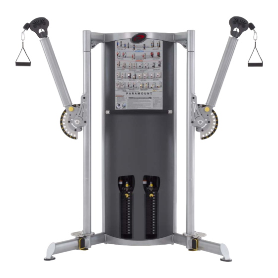
- Page 2 ESSAGE TO USTOMERS Thank you for purchasing the Paramount PFT-200 Functional Trainer. Because of the many unique features included in this product, this manual was created to provide you with information on how to properly assemble and maintain your equipment. Proper maintenance will ensure that your new equipment will last for years.
-
Page 3: Table Of Contents
ABLE OF ONTENTS ............................4 AFETY ....................7 ENERAL ARE AND AINTENANCE ......................8 ACHINE PECIFICATIONS ..........................9 REPARATION ......................10 SSEMBLING ACHINE ................12 PTIONAL NCREMENTAL DDER EIGHT YSTEM ......................15 PTIONAL CCESSORY & I ....................16 ABLE OUTING NFORMATION ........................... -
Page 4: Safety
9. If the machine appears damaged or inoperable, contact a facility staff member to place an “OUT OF ORDER, DO NOT USE” sign on the machine until it is repaired. Only use Paramount supplied replacement components to service this machine. - Page 5 3. Install this piece of equipment on a solid level surface that does not deviate more then 1/8” over a 10’ distance (or as defined and required by local building and architectural codes. 4. Paramount strongly recommends that all equipment be anchored to the floor to prevent movement and increase stability.
- Page 6 • Frames and Lifting Arms: Inspect weekly for integrity and function. Replace any component at first signs of wear. Use only Paramount supplied components. 4. Replace any warning label at first sign of wear. Labels and the Facility Safety Sign may be obtained from Paramount free of charge.
-
Page 7: General Care And Maintenance
13. Be sure all hardware is tight before using the machine. Retain these instructions for future reference. If you have any questions, do not hesitate to contact your Paramount dealer or Paramount Fitness Corp. at (800)721-2121 or [email protected]. -
Page 8: Machine Specifications
ACHINE PECIFICATIONS E A T U R E S • Two independent weight stacks (170 lb. per stack) • 2:1 weight stack reduction for low momentum movements. • 85 lb. max resistance at cable end (per handle). • (17) weight stack settings in 5 lb. increments (5 lb. - 85 lb.) •... -
Page 9: Preparation
REPARATION H A R D W AR E B AG C O N T E N T S ITEM DESCRIPTION PART SELECTOR PIN, MAGNETIC B 470 MOLDED FOOT S 550 SNAP HOOK B1005 STRAP HANDLE B1110A WEIGHT STACK LABEL B2173 85 LBS (38.5 KG.) W E I G H T P L A T E R E Q U I R E M E N T S Each machine requires (8) boxes of weight plates,... -
Page 10: Assembling The Machine
SSEMBLING THE ACHINE ASSEMBLE FEET TO BASE FRAME INSTALL WEIGHT PLATES GUIDE ROD RETAINER 1. Remove the rear panel held in place by the three thumbscrews at the top. CAP PLATE 2. If you ordered the optional adder GUIDE RODS weight system, remove the adder weight guide rods by pulling down on the adder weight guide rod retainers... - Page 11 SSEMBLING THE ACHINE INSTALL WEIGHT STACK LABELS 1. Verify that there are 16 weight plates installed on each stack. 2. Wipe the front surface of the weights with isopropyl alcohol and allow to dry completely. 3. Remove the backing from the label. Vertically center the 10 lb. label on the top weight and align the side of the label liner (front surface) with the outside edge of the pin hole in the weights.
-
Page 12: Optional Incremental Adder Weight System
PTIONAL NCREMENTAL DDER EIGHT YSTEM If you purchased your machine with the optional incremental adder weight system, it has been pre- installed. If you ordered the adder weight system after receiving the machine, these instructions will show you how to properly assemble it. The following parts are included with your kit: ITEM P UMBER ESCRIPTION... - Page 13 PTIONAL NCREMENTAL DDER EIGHT YSTEM E. Remove the pulley housing from the cap SEE TABLE ON PREVIOUS plate by unscrewing it from the selector PAGE FOR ITEM NUMBERS bar. F. Assemble the adder weight selector mechanism, thrust washers, wave spring PULLEY HOUSING washer, cover, and label plate to the cap plate as shown.
- Page 14 Make sure that it engages into the adder weight smoothly. Lubricate the guide rods using a Teflon based spray lubricant. Paramount recommends TriFlow brand. Test the system by placing the selector pin into the cap plate and engaging the adder weight.
-
Page 15: Optional Accessory Kit
PTIONAL CCESSORY ANGER If you purchased the optional accessory kit, these instructions will show you how to properly assemble it to your machine. 1. Remove the rear panel. REMOVE BOLTS 2. Remove the two bolts holding the balance bar. Have someone support the bar while you remove the bolts. -
Page 16: Cable Routing & Information
& S ABLE OUTING PECIFICATION CABLE RETAINER SCREWS REPLACE CABLES at the first sign of wear OR on an annual basis! Part number: PFT2010CBL100X... -
Page 17: Machine Labels
ACHINE ABELS The following are the Warning labels required for this PFT-200 machine. If any of these labels are missing or become damaged contact Paramount. Note: these labels are not to scale. B2051 B2084 B2612 LBL-PR-PFT200A LBL-WRN-PFT200A B2173 LBL-WRN-0011 BE ALERT! -
Page 18: Machine Disassembly
ACHINE ISASSEMBLY If you need to disassemble your machine for any reason (i.e. maneuver the machine through small doorway during installation), the diagram on the following page will show you the frame clamping locations. You will need the following tools: •Ratchet (1/2”... - Page 19 ACHINE ISASSEMBLY STEP 6 STEP 5 STEP 4 Pivot Column Support Column STEP 5 STEP 8...
-
Page 20: Service
O W T O B T A I N E R V I C E For warranty service, contact an Authorized Paramount Dealer or a Paramount Customer Service representative at 1-800-721-2121 or 1-323-721-2121. You can also email us at [email protected]. -
Page 21: Paramount Limited Warranty
Labor coverage applies only within the United States and Canada. • Warranties for parts and labor may vary outside the United States. Contact the Paramount Dealer within your geographic area for warranty terms. THE OBLIGATION OF PARAMOUNT UNDER THIS WARRANTY IS LIMITED TO REPAIRING OR REPLACING WARRANTED DEFECTIVE PARTS, AS PARAMOUNT MAY ELECT, AT PARAMOUNT'S PLANT IN LOS ANGELES, CALIFORNIA. -
Page 22: Parts Diagrams
ARTS IAGRAMS... - Page 23 ARTS IAGRAMS...
- Page 24 ARTS IAGRAMS...
- Page 25 ARTS IAGRAMS...
- Page 26 ARTS IAGRAMS...
- Page 27 ARTS IAGRAMS...
- Page 28 ARTS IAGRAMS...
- Page 29 ARTS IAGRAMS...
- Page 30 ARTS IAGRAMS...
- Page 31 ARTS IAGRAMS...
- Page 32 ARTS IAGRAMS...
- Page 33 ARTS IAGRAMS...
- Page 34 ARTS IAGRAMS...
- Page 35 ARTS IAGRAMS...
- Page 36 Paramount Fitness Corporation 6450 E. Bandini Blvd. Los Angeles, CA 90040-3185 Phone: 1-323-721-2121 Fax: 323-724-2000 1-800-721-2121 www.paramountfitness.com...