
Related Manuals for GE Monogram ZDP30_ _H


Summary of Contents for GE Monogram ZDP30_ _H
- Page 1 GE Consumer & Industrial TECHNICAL SERVICE GUIDE Monogram Dual Fuel Pro Ranges Monogram Gas Cooktops MODEL SERIES: ZDP30_ _H ZDP36_ _ _H ZDP48_ _ _H ZGU36_ _ _H ZGU48_ _ _H PUB # 31-9119 3/04...
- Page 2 If grounding wires, screws, straps, clips, nuts, or washers used to complete a path to ground are removed for service, they must be returned to their original position and properly fastened. GE Consumer & Industrial Technical Service Guide Copyright © 2004 All rights reserved.
-
Page 3: Table Of Contents
TABLE OF CONTENTS Blower Thermal Cutout ....................16 Burner Alignment ......................12 Burner Valve ........................11 Check for Proper Ignition ....................12 Component Access ......................8 Component Locator Views ....................6 Components ........................8 Convection Fan Assembly ....................18 Door Assemblies ....................... 9 Flame Characteristics ..................... -
Page 4: Introduction
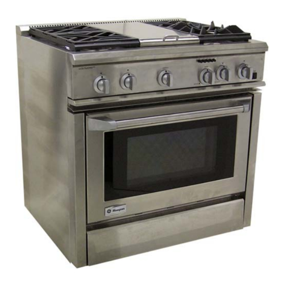
Introduction The Monogram Ranges are available in 30-in. 36-in. and 48-in. configurations. The 36-in. can have 6 burners, no grill or griddle or 4 burners with grill or griddle. The 30-in. and 36-in. models have a 27-in. self-cleaning oven and the 48-in. model has an additional 12-in. -
Page 5: Nomenclature
Nomenclature Model Number Z D P 4 8 N 4 G H 1 S S Monogram Stainless Steel Eng. Digit D = Dual Fuel Model Year G = Gas G = Grill and Griddle P = Self Clean R = Grill Only U= Cooktop D = Griddle Only 4 = Surface Burners... -
Page 6: Component Locator Views
Component Locator Views 36-in. Range Models 1 - Spark Module 6 - Relays 2 - Oven Select Switches 7 - Clean Timer 3 - Oven Control 8 - Terminal Block 4 - Door Lock High Limit 9 - Transformer 5 - Gas Shut-Off Valve –... - Page 7 48-in. Range Models 1 - Spark Module 6 - Relays 2 - Oven Select Switches 7 - Clean Timer and Proof Timer 3 - Oven Control 8 - Terminal Block 4 - Door Lock High Limit 9 - Transformer 5 - Gas Shut-Off Valve –...
-
Page 8: Component Access
Components 30-in. Range Models Component Access 1. Remove the manifold/valve panel. (See 36-in. All 36-in. and 48-in. Models and 48-in. Models.) 1. Remove the manifold/valve panel: 2. Remove the landing ledge: a. Remove the knobs from the control a. Remove the 4 Phillips head screws valves. -
Page 9: Door Assemblies
To install the door: Door Gasket 1. Firmly grasp the door at the top sides. This is The gasket is attached to the front frame around critical. the outer edge of the oven liner. A series of spring clips mounts the gasket to the front frame. The 2. -
Page 10: Oven Light Bulbs
Oven Light Bulbs Surface Burner To remove the surface burner: Socket 1. Lift off the burner cap and burner head. Receptacle 2. Remove the burner ring locking nut using a -in. socket wrench, crescent wrench or channel-lock pliers. 3. Lift off the burner ring. Do not remove the burner base. -
Page 11: Burner Valve
Flame Characteristics Burner Valve Burner flames should be blue and stable with no The burner valves are attached to the manifold by yellow tips. (Yellow tipping may be normal for LP two screws and contains an orifice which sets gas.) The flame should not have excessive noise the flow rate for the simmer flame. -
Page 12: Burner Alignment
Grates Ignition and Re-ignition To repair damaged feet on range cooktop grates, The ignition systems consists of 3 major order the repair kit, part # WB2X11095. components. • Transformer • Spark Module Burner Alignment • Electrodes and Associated Wiring Burner alignment is very important for proper Features of the cooktop determine whether the operation. -
Page 13: Grill Burner/Griddle Burner Ignition Systems (On Some Models)
Grill Burner/Griddle Burner Ignition Spark Module Systems (On Some Models) All 36-in. and 48-in. models have a single spark The grill burner and griddle burner are ignited by module located behind the manifold/valve panel. Norton style glowbar ignition systems. The ignition To remove the module: circuit consists of the grill switch (grill burner only), griddle thermostat (griddle burner only), the... -
Page 14: Griddle Removal
Grill Removal Griddle Removal To remove the grill burner assembly: To remove the griddle assembly: 1. Remove the grill cover, grill grates and grill 1. Remove the griddle cover. radiant. 2. Lift off the front trim from the front of the 2. -
Page 15: Griddle Leveling
Grill or Griddle Air Adjustment Griddle Leveling The 2 screws at the rear of the griddle plate 1. For the grill, remove the grill cover, grates and assembly are leveling screws. They can be grill radiant. For the griddle, remove the turned to level the griddle or to provide a forward griddle assembly (see Griddle Removal) -
Page 16: Blower Thermal Cutout
Grill or Griddle Igniter Removal Oven Thermostat Calibration The AVERAGE center oven temperature should 1. For the grill, remove the grill cover, grates and be 350° ±15°F for baking at the 350°F setting. grill radiant. For the griddle, remove the Customers may change the average center oven griddle assembly (see Griddle Removal) -
Page 17: Oven Select Switches
Oven Select Switches Relays, Convection Pulser Timers and Main Power Connection Select switch operation can be checked with ohmmeter and strip circuits that show what Electrical relays and timers are located in the contacts are closed in each mode of operation. compartment below the oven. -
Page 18: Convection Fan Assembly
Convection Fan Assembly The convection fan assembly is located behind the large oven liner. To remove the convection fan assembly: 1. Disconnect power and remove the oven door and racks. 2. Loosen the fan cover mounted by 4 screws and spacers. Lift the cover off the keyhole opening. 3. -
Page 19: Lock Motor Assembly
Lock Motor Assembly LOCKING The lock motor assembly is located at the center 120V. LATCH LOCK top of the oven front frame. The assembly "CLOSED" LIGHT RELAY consists of the mounting plate, motor, micro K3 RELAY switches, cam and hook assembly. COIL RELAY To access the assembly:... -
Page 20: Oven Blower Motor (30-In. Range Models)
Oven Blower Motor (30-in. Range Models ) The blower motor assembly is located on the back of the range above the oven. The air switch on the blower motor completes the circuit to the oven thermostat and hot wire relay. To remove the blower assembly: Reignition Module Screw... -
Page 21: Schematics And Wiring Diagrams
Schematics and Wiring Diagrams WARNING: Disconnect electrical power before servicing. Caution: Label all wires prior to disconnection. Wiring errors can cause improper and dangerous operation. Verify operation after servicing. Oven Circuits BAKE 27-in Oven CONVECTION BAKE 240V. HEAT HEAT LIGHT LIGHT LIGHT LIGHT... - Page 22 36-in. Range Wiring Diagram – 22 –...
- Page 23 36-in Range Schematic – 23 –...
- Page 24 48-in. Range Wiring Diagram – 24 –...
- Page 25 48-in Range Schematic – 25 –...
- Page 26 30-in Range Schematic – 26 –...
- Page 27 30-in. Range Wiring Diagram – 27 –...
- Page 28 Gas Cooktop Wiring Diagram – 28 –...
- Page 29 Gas Cooktop Wiring Schematic – 29 –...
-
Page 30: Warranty
Warranty MONOGRAM RANGE WARRANTY Proof of original purchase date is needed to obtain service under warranty. WHAT IS FULL ONE-YEAR WARRANTY This warranty is extended to the original purchaser and any succeeding owner for products COVERED For one year from date of original purchase, we purchased for ordinary home use in the 48 will provide, free of charge, parts and service mainland states, Hawaii and Washington, D.C.