HP Compaq Elite 8300 Maintenance & Service Manual
All-in-one business pc
Hide thumbs
Also See for Compaq Elite 8300:
- Reference manual (179 pages) ,
- Maintenance & service manual (168 pages) ,
- Specification (81 pages)

Related Manuals for HP Compaq Elite 8300


Summary of Contents for HP Compaq Elite 8300
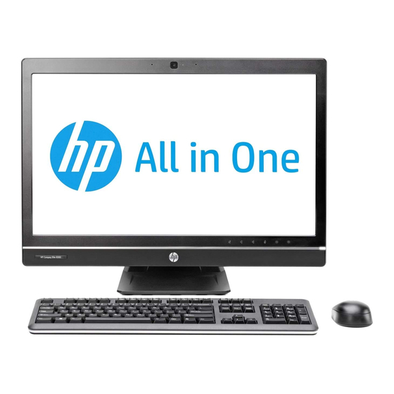
- Page 1 Maintenance & Service Guide HP Compaq Elite 8300 Touch All-in-One Business PC HP Compaq Elite 8300 All-in-One Business PC HP Compaq Pro 6300 All-in-One Business PC...
- Page 2 Microsoft and Windows are trademarks of Microsoft Corporation in the U.S. and other countries. The only warranties for HP products and services are set forth in the express warranty statements accompanying such products and services. Nothing herein should be construed as constituting an additional warranty.
-
Page 3: About This Book
About This Book WARNING! Text set off in this manner indicates that failure to follow directions could result in bodily harm or loss of life. CAUTION: Text set off in this manner indicates that failure to follow directions could result in damage to equipment or loss of information. -
Page 4: Table Of Contents
Computer Setup—File ....................... 14 Computer Setup—Storage ....................15 Computer Setup—Security ....................18 Computer Setup—Power ....................23 Computer Setup—Advanced ..................... 24 Recovering the Configuration Settings ....................26 4 HP PC Hardware Diagnostics ........................27 Why run HP PC Hardware Diagnostics – UEFI .................. 27... - Page 5 How to access and run HP PC Hardware Diagnostics - UEFI ............27 Downloading HP PC Hardware Diagnostics to a USB device ............28 5 Serial ATA (SATA) Drive Guidelines and Features ..................29 SATA Hard Drives ..........................29 SATA Hard Drive Cables ........................29 SATA Data Cable ......................
- Page 6 Replacing drives ..........................49 Replacing the hard disc drive with a 3.5-inch hard disc drive or a single 2.5-inch drive ..49 Replacing the optical disc drive ..................53 Memory .............................. 56 Replacing the battery ......................... 59 Serial port ............................61 Webcam module ..........................
- Page 7 Solving Keyboard and Mouse Problems ..................138 Solving Hardware Installation Problems ................... 140 Solving Network Problems ....................... 142 Solving Memory Problems ....................... 145 Solving Processor Problems ......................147 Solving CD-ROM and DVD Problems ....................147 Solving USB Flash Drive Problems ....................149 Solving Front Panel Component Problems ..................
- Page 8 Country-specific requirements ......................182 Appendix B Specifications ..........................183 8300 models ............................. 183 6300 models ............................. 184 Index ................................. 185...
-
Page 9: Product Features
Product Features Overview Figure 1-1 HP Compaq All-in-One Business PC (model 8300 shown) The HP Compaq All-in-One Business PC offers the following features: ● Integrated All-in-One form factor ● Full HD, LCD display (1920 x 1080) with LED backlighting ◦... - Page 10 Optional mSATA module that can be used as a cache or SSD for the Elite 8300 or as a second drive for the Pro 6300 ● Intel Q77 Express chipset – Intel vPro (HP Compaq Elite 8300 All-in-One Business PC) ● Intel Q75 Express chipset (HP Compaq Pro 6300 All-in-One Business PC) ●...
-
Page 11: Front Components
Front components NOTE: Front components are the same for 6300 and 8300 models. Figure 1-2 Front components Table 1-1 Front components Component Component Webcam with privacy shutter (optional) Mute speaker Dual microphone array (with optional webcam) Reduce volume Webcam activity LED (with optional webcam) Increase volume 16:9 widescreen LED-backlit LCD display Mute microphone... -
Page 12: Side Components
Table 1-2 Side components Component Component Hard disc drive activity LED Tray-load optical disc drive HP 6-in-1 media card reader (optional) Optical disc drive eject button (2) USB 3.0 ports Optical disc drive activity LED Microphone/line in jack Power button... -
Page 13: Rear Components
Rear components NOTE: Rear components are the same for 6300 and 8300 models. Figure 1-4 Rear components Table 1-3 Rear components Component Component Access panel DisplayPort connector Access panel latches RJ-45 Gigabit Ethernet port Security lock slot Stereo audio line out Power connector Rear port cover (2) PS/2 mouse and keyboard connectors... -
Page 14: Adjusting The Tilt/Swivel Base
Adjusting the tilt/swivel base Tilt the computer forward up to -5 degrees or backward up to +30 degrees to set it to a comfortable eye level. Figure 1-5 Adjusting tilt The tilt/swivel base has a swivel pad on the underside that allows you to swivel the computer up to 360 degrees left or right for the best viewing angle. -
Page 15: Height Adjustable/Recline Stand (Optional)
Height adjustable/recline stand (optional) An optional stand may be purchased to allow ● height adjustment of 110 mm (4.3 inches) ● rotation from landscape to portrait position ● tilt backward up to +60 degrees ● recline to 30 degrees from the desktop WARNING! If the height adjustable/recline stand is installed, before laying the computer down for service, position the computer vertically by grasping the sides of the display, and then raise the... - Page 16 To install the height adjustable stand: Insert the stand into the slots in the rear of the computer. Figure 1-8 Installing the height adjustable stand Install the screws that secure the stand to the computer. Figure 1-9 Installing the height adjustable stand screws Chapter 1 Product Features...
-
Page 17: Activating And Customizing The Software
This process takes about 5 to 10 minutes. Carefully read and follow the instructions on the screen to complete the activation. We recommend that you register your computer with HP during operating system setup so you can receive important software updates, facilitate support questions, and sign up for special offers. -
Page 18: Downloading Windows 7 Updates
This process takes about 5 to 10 minutes. Carefully read and follow the instructions on the screen to complete the activation. We recommend that you register your computer with HP during operating system set up so you can receive important software updates, facilitate support questions, and sign up for special offers. You can also register your computer with HP using the Register with HP app on the Start screen. -
Page 19: Downloading Windows 8 Updates
Downloading Windows 8 updates Microsoft may release updates to the operating system. To help keep the computer running optimally, HP recommends checking for the latest updates during the initial installation and periodically throughout the life of the computer. Run Windows Update as soon as possible after you set up your computer. -
Page 20: Computer Setup (F10) Utility
Computer Setup (F10) Utility Computer Setup (F10) Utilities Use Computer Setup (F10) Utility to do the following: ● Change factory default settings. ● Set the system date and time. ● Set, view, change, or verify the system configuration, including settings for processor, graphics, memory, audio, storage, communications, and input devices. -
Page 21: Using Computer Setup (F10) Utilities
● Solve system configuration errors detected but not automatically fixed during the Power-On Self- Test (POST). ● Replicate the system setup by saving system configuration information on a USB device and restoring it on one or more computers. ● Execute self-tests on a specified ATA hard drive (when supported by drive). ●... -
Page 22: Computer Setup-File
Computer Setup—File NOTE: Support for specific Computer Setup options may vary depending on the hardware configuration. Table 3-2 Computer Setup—File Option Description System Information Lists: ● Product name ● SKU number ● Processor type/speed/stepping ● Cache size (L1/L2/L3) (dual core processors have this listed twice) ●... -
Page 23: Computer Setup-Storage
Computer Setup—Storage NOTE: Support for specific Computer Setup options may vary depending on the hardware configuration. Table 3-3 Computer Setup—Storage Option Description Device Configuration Lists all installed BIOS-controlled storage devices. When a device is selected, detailed information and options are displayed. The following options may be presented: ●... - Page 24 This setting affects only the port with the black connector, labeled as eSATA on the system board. This port should have the eSATA back panel connector attached to use eSATA drives. For more information, see the eSATA white paper at www.hp.com. SATA Emulation Allows you to choose how the SATA controller and devices are accessed by the operating system.
- Page 25 Table 3-3 Computer Setup—Storage (continued) DPS Self-Test Allows you to execute self-tests on ATA hard drives capable of performing the Drive Protection System (DPS) self-tests. NOTE: This selection will only appear when at least one drive capable of performing the DPS self-tests is attached to the system.
-
Page 26: Computer Setup-Security
Computer Setup—Security NOTE: Support for specific Computer Setup options may vary depending on the hardware configuration. Table 3-4 Computer Setup—Security Option Description Setup Password Allows you to set and enable a setup (administrator) password. NOTE: If the setup password is set, it is required to change Computer Setup options, flash the ROM, and make changes to certain plug and play settings under Windows. - Page 27 Table 3-4 Computer Setup—Security (continued) Device Security Allows you to set Device Available/Device Hidden (default is Device Available) for: ● Embedded security device ● System audio ● USB controller (varies by model) ● Network controller NOTE: You must disable AMT before trying to hide the network controller. ●...
- Page 28 Table 3-4 Computer Setup—Security (continued) Master Boot Record Enables/disables Master Boot Record (MBR) security. Security The MBR contains information needed to successfully boot from a disk and to access the data stored on the disk. Master Boot Record Security may prevent unintentional or malicious changes to the MBR, such as those caused by some viruses or by the incorrect use of certain disk utilities.
- Page 29 Table 3-4 Computer Setup—Security (continued) System Security Data Execution Prevention (enable/disable) - Helps prevent operating system security breaches. (these options are Default is enabled. hardware dependent) SVM CPU Virtualization (enable/disable). Controls the virtualization features of the processor. Changing this setting requires turning the computer off and then back on. Default is disabled. Virtualization Technology (VTx) (enable/disable) - Controls the virtualization features of the processor.
- Page 30 (PK) that verifies kernels during system start up, allowing you to use alternative operating systems. Selecting HP Keys causes the computer boot using the preloaded HP-specific boot keys. Default is HP Keys.
-
Page 31: Computer Setup-Power
Computer Setup—Power NOTE: Support for specific Computer Setup options may vary depending on the hardware configuration. Table 3-5 Computer Setup—Power Option Description ● OS Power Idle Power Savings—Extended/Normal. Allows certain operating systems to decrease the Management processors power consumption when the processor is idle. Default is extended. ●... -
Page 32: Computer Setup-Advanced
Computer Setup—Advanced NOTE: Support for specific Computer Setup options may vary depending on the hardware configuration. Table 3-6 Computer Setup—Advanced (for advanced users) Option Heading Power-On Options Allows you to set: ● POST mode (QuickBoot, Clear Memory, FullBoot, or FullBoot Every x Days). ◦... - Page 33 Table 3-6 Computer Setup—Advanced (for advanced users) (continued) BIOS Power-On Allows you to set the computer to turn on automatically at a time you specify. Onboard Devices Allows you to set resources for or disable Legacy devices. Select the Legacy device's IRQ, DMA, and I/O Range. The settings may not take effect for all operating systems.
-
Page 34: Recovering The Configuration Settings
Table 3-6 Computer Setup—Advanced (for advanced users) (continued) VGA Configuration Displayed only if there is an add-in video card in the system. Allows you to specify which VGA controller will be the “boot” or primary VGA controller. AMT Configuration Allows you to set: ●... -
Page 35: Hp Pc Hardware Diagnostics
HP PC Hardware Diagnostics To help troubleshoot and diagnose failures, use the UEFI-based hardware diagnostic solution that HP includes on all products. This tool can even be used if the computer will not boot to the operating system. Why run HP PC Hardware Diagnostics – UEFI The HP PC Hardware Diagnostic tools simplify the process of diagnosing hardware issues and expedite the support process when issues are found. -
Page 36: Downloading Hp Pc Hardware Diagnostics To A Usb Device
Enter the product name in the text box and click Search. Select your specific computer model. Select your operating system. In the Diagnostic section, click the HP UEFI Support Environment link. This link provides additional information. - or - Click the Download button and select Run. The download includes instructions (in English) on how to install the tools on the USB device. -
Page 37: Serial Ata (Sata) Drive Guidelines And Features
3.0 Gb/s SATA Hard Drive Cables SATA Data Cable Always use an HP approved SATA 3.0 Gb/s cable as it is fully backwards compatible with the SATA 1.5 Gb/s drives. Current HP desktop products ship with SATA 3.0 Gb/s hard drives. -
Page 38: Smart Ata Drives
SMART ATA Drives The Self Monitoring Analysis and Recording Technology (SMART) ATA drives for the HP Personal Computers have built-in drive failure prediction that warns the user or network administrator of an impending failure or crash of the hard drive. The SMART drive tracks fault prediction and failure indication parameters such as reallocated sector count, spin retry count, and calibration retry count. -
Page 39: Routine Care And Disassembly Preparation
Routine Care and Disassembly Preparation This chapter provides general service information for the computer. Adherence to the procedures and precautions described in this chapter is essential for proper service. CAUTION: When the computer is plugged into an AC power source, voltage is always applied to the system board. -
Page 40: Electrostatic Discharge Information
Electrostatic discharge information A sudden discharge of static electricity from your finger or other conductor can destroy static-sensitive devices or microcircuitry. Often the spark is neither felt nor heard, but damage occurs. An electronic device exposed to electrostatic discharge (ESD) may not appear to be affected at all and can work perfectly throughout a normal cycle. -
Page 41: Personal Grounding Methods And Equipment
● Always be properly grounded when touching a sensitive component or assembly. ● Avoid contact with pins, leads, or circuitry. ● Place reusable electrostatic-sensitive parts from assemblies in protective packaging or conductive foam. Personal grounding methods and equipment Use the following equipment to prevent static electricity damage to equipment: ●... -
Page 42: Operating Guidelines
● Conductive bins and other assembly or soldering aids ● Conductive foam ● Conductive tabletop workstations with ground cord of one-megohm +/- 10% resistance ● Static-dissipative table or floor mats with hard tie to ground ● Field service kits ● Static awareness labels ●... -
Page 43: Routine Care
Routine Care General cleaning safety precautions Never use solvents or flammable solutions to clean the computer. Never immerse any parts in water or cleaning solutions; apply any liquids to a clean cloth and then use the cloth on the component. Always unplug the computer when cleaning with liquids or damp cloths. -
Page 44: Cleaning The Display
If an incorrect screw is used during the reassembly process, it can damage the unit. HP strongly recommends that all screws removed during disassembly be kept with the part that was removed, then returned to their proper locations. -
Page 45: Cables And Connectors
Batteries, battery packs, and accumulators should not be disposed of together with the general household waste. In order to forward them to recycling or proper disposal, please use the public collection system or return them to HP, their authorized partners, or their agents. Service Considerations... -
Page 46: Removal And Replacement Procedures All-In One (Aio) Chassis
Place the computer face down on a soft flat surface. HP recommends that you set down a blanket, towel, or other soft cloth to protect the screen surface from scratches or other damage. -
Page 47: Removing The Rear Port Cover
Removing the rear port cover If a cable lock is installed on the rear of the unit, remove the lock. Grasp the rear port cover, then pull it down and off the computer. NOTE: Removing the rear port cover may require that you use a significant amount of force. NOTE: If using forceful pressure on the ribs does not remove security cover, grip the exposed edge of the security cover by the AC plug and pull it straight out. -
Page 48: Installing An Access Panel Security Screw
Installing an access panel security screw You may prevent access to internal components by securing the access panel. Screw a T15 tamper- resistant Torx screw through the left latch of the access panel to prevent removal of the panel. NOTE: Spare parts for the security screw or associated hardware are not provided. - Page 49 Insert the wireless receiver into a USB 2.0 port on the computer. NOTE: Insert the wireless receiver into a USB 2.0 port that is separated from USB 3.0 devices. Figure 7-4 Installing the wireless receiver Make sure the Power switch on the bottom of the mouse is in the On position. Press and release the Connect button on the bottom of the mouse.
-
Page 50: Access Panel
Access panel The computer has one main rear access panel that allows access to internal components. To remove the access panel: Prepare the computer for disassembly (see Preparing to disassemble the computer on page 38). Slide the access panel latches toward the edges of the unit, then slide the access panel toward the top of the computer until it slides off the unit. - Page 51 To replace the access panel, hold the panel at a 90-degree angle, place the top into the guides in the chassis, and then press down to align it with the guides. Figure 7-7 Replacing the access panel NOTE: Align the bottom of the access panel with the notches on the outside edge of the computer (1) when installing.
-
Page 52: Stand
Stand The stand is secured with two captive Torx screws. You must remove a plastic cover to gain access to the screws. You must remove the access panel to remove the stand. To remove the stand: Prepare the computer for disassembly (see Preparing to disassemble the computer on page 38). - Page 53 Lift the stand up and off the computer. Figure 7-11 Removing the stand To replace the stand, reverse the removal procedures. Stand...
-
Page 54: Lower Panel
Lower panel The lower panel is located under the stand and on the bottom part of the computer. Figure 7-12 Lower panel location To remove the access panel: Prepare the computer for disassembly (see Preparing to disassemble the computer on page 38). -
Page 55: Metal Plate
Metal plate The metal plate is located under the stand. Figure 7-14 Metal plate location To remove the metal plate: Prepare the computer for disassembly (see Preparing to disassemble the computer on page 38). Remove the access panel (see Access panel on page 42). - Page 56 Slide the metal plate left to the left (2), and then lift it off the chassis (3). Figure 7-15 Removing the metal plate To replace the lower panel, reverse the removal procedures. Chapter 7 Removal and Replacement Procedures All-in One (AIO) Chassis...
-
Page 57: Replacing Drives
Replacing drives Replacing the hard disc drive with a 3.5-inch hard disc drive or a single 2.5-inch drive The hard disc drive is located behind the access panel on the left side of the computer (when viewed from behind). The drive is housed in a removable cage. Figure 7-16 Hard drive location If you choose to install an optional 2.5-inch solid state drive (SSD) or self-encrypting drive (SED), you... - Page 58 Pull the latch next to the lower side of the hard disc drive cage away from the cage to release it, then slide the cage toward the edge of the chassis and lift it out. Figure 7-17 Removing the hard disc drive cage Lift the latch on one side of the hard disc drive cage and pull the hard disc drive out of the cage.
- Page 59 Remove the four mounting screws from the hard disc drive. Be sure to keep the blue rubber grommets with each screw. Figure 7-19 Removing the mounting screws Screw the four mounting screws into the new hard disc drive. Be sure to keep the blue rubber grommets behind each screw.
- Page 60 Slide the new hard disc drive, or drive adapter bracket holding an optional 2.5-inch drive, into the cage until it snaps in place. Be sure that the connector on the hard disc drive is at the opening of the cage. Figure 7-21 Inserting the hard disc drive into the cage With the hard disc drive connector facing toward the center of the chassis, place the hard disc...
-
Page 61: Replacing The Optical Disc Drive
Replacing the optical disc drive The optical disc drive is located above the hard disc drive on the left side of the computer (when viewed from behind). The optical drive data cable connects to the SATA2 and SATA PWR2 system board connectors. NOTE: The drive bracket is not spared. - Page 62 Lift the tab at the back of the optical disc drive enclosure to release the drive. Figure 7-24 Removing the optical disc drive NOTE: When replacing an optical drive, remove the bracket from the old drive and install it on the new drive.
- Page 63 Secure the optical disc drive bracket to the new drive with the two screws. Figure 7-26 Attaching the optical disc drive bracket Align the new optical disc drive with the opening in the side of the computer. Push the drive in firmly until it snaps into place.
-
Page 64: Memory
Memory Memory modules are located on the right side of the computer (viewed from behind). The computer has two memory slots. Figure 7-28 Memory module location For proper system operation, the SODIMMs must be: ● industry-standard 204-pin ● unbuffered non-ECC PC3-10600 DDR3-1600 MHz-compliant ●... - Page 65 Preparing to disassemble the computer on page 38). Place the computer face down on a soft flat surface. HP recommends that you set down a blanket, towel, or other soft cloth to protect the screen surface from scratches or other damage.
- Page 66 To install a memory module, slide the SODIMM into the socket at approximately a 30° angle (1), then press the SODIMM down (2) so that the latches lock it in place. Figure 7-30 Installing a memory module NOTE: A memory module can be installed in only one way. Match the notch on the module with the tab on the memory socket.
-
Page 67: Replacing The Battery
The lithium battery is only used when the computer is NOT connected to AC power. HP encourages customers to recycle used electronic hardware, HP original print cartridges, and rechargeable batteries. For more information about recycling programs, go to http://www.hp.com/... - Page 68 Remove the access panel (see Access panel on page 42). The battery can now be seen on the lower right side of the fan. Figure 7-32 Locating the battery To release the battery from its holder, squeeze the metal clamp that extends above one edge of the battery.
-
Page 69: Serial Port
Serial port The serial port is located near the bottom of the computer below the hard drive. It is secured with one Phillips screw. Figure 7-34 Serial port location To remove the serial port: Prepare the computer for disassembly (see Preparing to disassemble the computer on page 38). - Page 70 Remove the cable from its routing path (3), and remove the serial port assembly from the computer. Figure 7-35 Removing the serial port To install the serial port, reverse the removal procedures. Chapter 7 Removal and Replacement Procedures All-in One (AIO) Chassis...
-
Page 71: Webcam Module
Webcam module On products that ship with a webcam module, the module is located at the top of the computer beneath the top panel. It is secured with two silver Phillips screws and has one connector. The webcam module is optional. Figure 7-36 Webcam module location To remove the webcam module:... - Page 72 Remove the two Torx screws that secure the webcam module bracket to the computer. Figure 7-37 Removing the webcam module Rotate the assembly to gain access to the connector on the module, and then disconnect the cable from the module. Figure 7-38 Disconnecting the webcam module cable Chapter 7 Removal and Replacement Procedures All-in One (AIO) Chassis...
- Page 73 To remove the module from the bracket, remove the two Phillips screws that secure the module, and then separate the module from the bracket. Figure 7-39 Disconnecting the webcam module cable To install a webcam module, reverse the removal procedures. Webcam module...
-
Page 74: Converter Board
Converter board The converter board is located on the left side of the computer (viewed from behind) under the main rear cover. It is secured with two Torx screws and has two connectors. Use the same converter spare part for all display panels; however, you must change jumper settings on the board based on the display panel. - Page 75 Remove the two black Torx screws (2) that secure the board to the computer. Note the converter board jumper settings stamped on the chassis (3). Be sure to correctly position the jumpers on the converter board for the installed display panel. Figure 7-41 Removing the converter board Lift the converter board from the computer.
- Page 76 21.5-inch 23.0-inch To install the converter board, reverse the removal procedures. Chapter 7 Removal and Replacement Procedures All-in One (AIO) Chassis...
-
Page 77: Touch Sensor Board
Touch sensor board NOTE: The touch sensor board is located on the right side of the computer (viewed from behind) above the system board. It is secured with one Torx screw and has three connectors. Touch sensor boards are spared with the touch panel spare part kit. Be sure to replace the touch sensor board when replacing a touch display panel. - Page 78 Remove the Torx screw (2) that secures the board to the computer. Figure 7-43 Removing the touch sensor board Lift the touch sensor board from the computer. To install the touch sensor board, reverse the removal procedures. Chapter 7 Removal and Replacement Procedures All-in One (AIO) Chassis...
-
Page 79: Heat Sinks - Graphics Board And Processor
Heat sinks – Graphics board and processor Separate heat sinks cool the discrete graphic board (select models only) and the processor. If installed, you must remove the smaller graphics heat sink before you can remove the larger processor heat sink. The graphics heat sink is secured with three Torx screws –... -
Page 80: Processor Heat Sink - Model 6300
Loosen the two silver captive Torx screws on the heat sink (2), and then lift the heat sink out of the computer (3). CAUTION: Remove heat sink retaining screws in diagonally opposite pairs (as in an X) to even the downward forces on the processor. This is especially important as the pins on the socket are very fragile and any damage to them may require replacing the system board. -
Page 81: Processor Heat Sink - Model 8300
In the order indicated on the heat sink, loosen the four silver captive Torx screws (1) – (4), and then lift the heat sink out of the computer (5). CAUTION: Remove heat sink retaining screws in diagonally opposite pairs (as in an X) to even the downward forces on the processor. - Page 82 Lift the heat sink assembly from the computer (6). CAUTION: To reduce a degradation in thermal performance, be sure not to touch the thermal grease on the surface of the processor or the heat sink. Figure 7-47 Removing the processor heat sink — 8300 models If you need to remove the fan from the heat sink, remove the three small Phillips screws that secure the fan to the heat sink, and lift the fan from the heat sink.
-
Page 83: Processor
Processor Prepare the computer for disassembly (see Preparing to disassemble the computer on page 38). Remove the access panel (see Access panel on page 42). Remove the graphics heat sink (see Graphics heat sink on page 71). Remove the processor heat sink (see Processor heat sink –... -
Page 84: Msata Solid-State Drive
After installing a new processor onto the system board, always update the system ROM to ensure that the latest version of the BIOS is being used on the computer. The latest system BIOS can be found on the Web at: http://h18000.www.hp.com/support. mSATA Solid-State Drive The mSATA SSD is located on the bottom of the system board. -
Page 85: Wlan Module
The WLAN module is located on the left side of the system board. The module is secured with one Phillips screw and has two connected antennas. NOTE: The procedure to replace the WLAN module must be performed by an HP technician. Figure 7-51 WLAN module location... - Page 86 Remove the lower panel (see Lower panel on page 46). Remove the metal plate (see Metal plate on page 47). Disconnect the antenna cables from the module (1). Remove the Phillips screw (2) that secures the module to the computer. Figure 7-52 Removing the WLAN module screw and antennas Chapter 7 Removal and Replacement Procedures All-in One (AIO) Chassis...
- Page 87 Lift the module to a 45-degree angle (1), and then pull it away to remove it from the socket (2). Figure 7-53 Removing the WLAN module To install the WLAN module, reverse the removal procedures. NOTE: WLAN modules are designed with a notch to prevent incorrect insertion. WLAN module...
-
Page 88: Graphics Board
Graphics board The graphics board is secured with two Torx screws. Removing it allows access to the webcam and allows you to remove the main rear cover. Figure 7-54 Graphics board location To remove the graphics board: Prepare the computer for disassembly (see Preparing to disassemble the computer on page 38). - Page 89 Rotate the board upward (2), and then pull it up and away from the connector to remove it from the computer (3). Figure 7-55 Removing the graphics board To replace the graphics board, reverse the removal procedures. Graphics board...
-
Page 90: Speakers
Speakers On products that ship with speakers, the speakers are located at the bottom of the computer. Two separate speakers are each secured by two Torx screws. To remove the right speaker you have to remove the power supply plug. Speakers are optional. -
Page 91: Fan
The fan is located near the middle of the computer and is secured with three Torx screws. You have to remove the metal plate to remove the fan.. To remove the fan assembly: Prepare the computer for disassembly (see Preparing to disassemble the computer on page 38). -
Page 92: Side Panels
Side panels The side panels are located one each side of the computer. They are secured with tabs, and the removal procedures are similar for both panels. Figure 7-59 Side panel locations To remove the side panels: Prepare the computer for disassembly (see Preparing to disassemble the computer on page 38). - Page 93 Rotate the panel out and off of the computer (2). NOTE: The removal and replacement procedures are similar for both panels. Figure 7-60 Removing the side panels (left side shown) To install the side panels, reverse the removal procedures. Side panels...
-
Page 94: Power Supply
Power supply The power supply is located at the middle, bottom of the computer. It is secured with two Torx screws. The power connector mounts separately with one Torx screw. The power supply slides out of the bottom of the bracket that secures it. Figure 7-61 Power supply location To remove the power supply:... - Page 95 Remove the Torx screw (1) that secures the power connector to the computer, and then lift the connector from atop the speaker (2). Figure 7-62 Removing the power connector Disconnect the cable from the system board connector (1). Position the cable above the power supply (2). Positioning the cable above the power supply makes it easier to slide the power supply downward and out of the bracket that secures it.
- Page 96 Slide the power supply downward and out of the bracket that houses it. Figure 7-64 Sliding the power supply out of the housing To install the power supply, reverse the removal procedures. Chapter 7 Removal and Replacement Procedures All-in One (AIO) Chassis...
-
Page 97: System Board
System board The system board is located on the right side of the computer (viewed from the rear). It is secured with eight Torx screws. To remove the system board: Prepare the computer for disassembly (see Preparing to disassemble the computer on page 38). - Page 98 Remove the cable mounting bracket by removing the Torx screw (1), and then sliding it up (2) and lifting it out of the computer. Figure 7-65 Removing the cable mounting bracket On model 6300, remove the eight Torx screws (1) that secure the system board to the computer. On model 8300, remove the ten Torx screws that secure the system board to the computer.
- Page 99 Slide the system board toward the top of the computer (3), and then lift up the board from left side to prevent interference between the side I/O bracket with the I/O ports on board. Figure 7-66 Removing the system board (model 6300 shown) To install the system board, reverse the removal procedures.
- Page 100 When replacing the system board, be sure to route the cables correctly. See the following images for cable routing. Route the following cables from under the system board cable mounting bracket: ● Display (LVDS) ● Optical drive data (SATA) ● Optical drive power ●...
- Page 101 Route the following cables from under the power supply: ● Power button board ● Hard drive data (SATA) ● Hard drive power ● Hood sensor System board...
- Page 102 Updating SMBIOS Information When replacing the system board, you must reprogram the SMBIOS information on the affected computer. Failure to reprogram the board will result in eventual failure, such as an activation failure (need to reactivate the system) or a system recovery failure. To update SMBIOS information in Computer Setup: Turn on or restart the computer.
-
Page 103: Card Reader Board
Card reader board The card reader board is located on the right side of the system board. It is secured with two screws. Figure 7-67 Card reader board location To remove the card reader board: Prepare the computer for disassembly (see Preparing to disassemble the computer on page 38). - Page 104 Remove the two Phillips screws (1) that secure the board to the system board. Figure 7-68 Removing the card reader board screws Lift the board to a 45-degree angle (1), and then pull it away to remove it from the socket (2). Figure 7-69 Removing the card reader board To install the card reader board, reverse the removal procedures.
-
Page 105: Power Button Board
Power button board The power button board is located on the bottom left corner of the computer. It is covered by a Mylar shield and has two connectors and one screw. Figure 7-70 Power button board location To remove the power button board: Prepare the computer for disassembly (see Preparing to disassemble the computer on page 38). - Page 106 Remove the Torx screw (1) that secures the Mylar that covers the power button board, and then lift the Mylar from the computer (2). NOTE: On some models, the left screw that secures the left speaker (when viewed from the rear) may also secure the Mylar.
- Page 107 Disconnect the two cables (1) from the board, and then remove the Torx screw that secures the board to the computer (2). Figure 7-72 Removing the power button board Remove the power button board from the computer. To install the power button board, reverse the removal procedures. Power button board...
-
Page 108: Front Bezel
Front bezel The front bezel is located on the front of the computer and is secured to the main system bracket with eight Torx screws. Replacement bezels include the webcam shutter and capacitive sensor board. On models that do not include a webcam, you must remove the shutter and install the webcam insert (Webcam assembly kit) into the slot in which the webcam would otherwise be installed. - Page 109 Remove the Torx screws that secure the bezel to the main system bracket assembly, as follows: ● Model 6300: 11 total screws ◦ Left: 2 screws ◦ Top: 4 screws ◦ Right 2 screws ◦ Bottom: 2 screw Figure 7-74 Front bezel assembly screw locations –...
- Page 110 ◦ Right 4 screws ◦ Bottom: 2 screw Figure 7-75 Front bezel assembly screw locations – 8300 models Lift the bracket from the bezel. To install the front bezel, reverse the removal procedures. 102 Chapter 7 Removal and Replacement Procedures All-in One (AIO) Chassis...
-
Page 111: Antenna
Antenna The antenna route from the WLAN card to the top of the computer. To remove the antenna: Prepare the computer for disassembly (see Preparing to disassemble the computer on page 38). Remove the access panel (see Access panel on page 42). - Page 112 Remove the two Torx screws that secure each antenna to the frame. Figure 7-76 Removing the antenna Figure 7-77 Removing the antenna 104 Chapter 7 Removal and Replacement Procedures All-in One (AIO) Chassis...
-
Page 113: Display Panel
Note the routing path for each antenna for replacement. Figure 7-78 Antenna routing paths To install the antenna, reverse the removal procedures. Display panel Model 6300 offers three different display panels – LG, AUO, and CMI. Model 8300 offers three different display panels – LG, Samsung, and CMI. Display panels require a backlight cable specific to the manufacturer. - Page 114 Remove the power supply (see Power supply on page 86). Remove the speakers (see Speakers on page 82). Remove the side panels (see Side panels on page 84). Remove the front bezel (see Front bezel on page 100). Disconnect the backlight cable from the display panel. NOTE: Replace the backlight cable with the new backlight cable that comes with the new display panel kit.
- Page 115 Model 6300: Remove the four Torx screws that secure the display panel to the frame. The screw locations for each manufacturer are stamped into the metal. The LG (1) and AUO (2) panels are secured with two screws on each side (left and right). Figure 7-80 Display panel screw locations –...
- Page 116 Model 8300: Remove the four Torx screws that secure the display panel to the frame. The screw locations for each manufacturer are stamped into the metal. The LG (1) and AUO (2) panels are secured with two screws on each side (left and right). Figure 7-82 Display panel screw locations –...
- Page 117 Disconnect the display cable from the display panel by pressing in on the tabs (1) on the side of the connector, and pulling the cable from the connector (2). Figure 7-84 Disconnecting the display cable from the display panel Be sure to correctly position the jumpers on the converter board for the installed display panel, as follows: CAUTION: Incorrect jumper placement can result in damage to the converter board and display...
- Page 118 21.5-inch 23.0-inch To install a display panel, reverse the removal procedures. When replacing a touch display panel, be sure to route the ZIF cables through separate holes in the frame so they correctly connect to the touch sensor board. 110 Chapter 7 Removal and Replacement Procedures All-in One (AIO) Chassis...
-
Page 119: Hood Sensor
Hood sensor The hood sensor is located on the bottom left of the computer (when viewed from behind). Figure 7-85 Hood sensor location To remove the hood sensor: Prepare the computer for disassembly (see Preparing to disassemble the computer on page 38). - Page 120 Remove the cable from its routing path. Figure 7-86 Hood sensor cable routing path Slide the hood sensor out of its slot built into the chassis. NOTE: the hood sensor fits tightly into the slot. Removal may require a flat-blade screwdriver to help disengage it.
-
Page 121: Hard Drive And Optical Drive Cables And Connectors
Hard drive and optical drive cables and connectors The hard drive and optical drive connectors are located near the middle of the computer, partially under the main display bracket. Each connector is secured with two Torx screws and has two cables that connect to the system board. - Page 122 Disconnect the hard drive cables or the optical drive cables from the system board. NOTE: Be careful not to damage the cable when disconnecting it from the board. Do not pull on the wires. Remove the connector from the computer. Figure 7-89 Removing the hard drive or optical drive connectors To install the hard drive or optical drive connector, reverse the removal procedures.
-
Page 123: Troubleshooting Without Diagnostics
If you are having problems with the computer, try the appropriate solutions below to try to isolate the exact problem before calling for technical support. ● Run the HP diagnostic tool. ● Run the hard drive self-test in Computer Setup. Refer to... -
Page 124: Helpful Hints
Helpful Hints on page 116 in this guide. To assist you in resolving problems online, HP Instant Support Professional Edition provides you with self-solve diagnostics. If you need to contact HP support, use HP Instant Support Professional Edition's online chat feature. Access HP Instant Support Professional Edition at: http://www.hp.com/... - Page 125 ● Wake the computer by pressing any key on the keyboard or pressing the power button. If the system remains in suspend mode, shut down the computer by pressing and holding the power button for at least four seconds then press the power button again to restart the computer. If the system will not shut down, unplug the power cord, wait a few seconds, then plug it in again.
-
Page 126: Solving General Problems
Solving General Problems You may be able to easily resolve the general problems described in this section. If a problem persists and you are unable to resolve it yourself or if you feel uncomfortable about performing the operation, contact an authorized dealer or reseller. WARNING! When the computer is plugged into an AC power source, voltage is always applied to the system board. - Page 127 In case of forgotten password, power loss, or computer malfunction, you must manually disable the Smart Cover lock . A key to unlock the Smart Cover Lock is not available from HP. Keys are typically available from a hardware store. Poor performance. Cause Solution Processor is too hot.
- Page 128 Table 8-1 Solving General Problems (continued) Poor performance. Cause Solution Virus resident on the hard drive. Run virus protection program. Too many applications running. Windows 7: Close unnecessary applications to free up memory. Add more memory. Some applications run in the background and can be closed by right-clicking on their corresponding icons in the task tray.
- Page 129 Computer powered off automatically and the Power LED flashes Red two times, once every second, followed by a two second pause, and the computer beeps two times. (Beeps stop after fifth iteration but LEDs continue flashing). Cause Solution Processor thermal protection activated: Ensure that the computer air vents are not blocked and the processor cooling fan is running.
-
Page 130: Solving Power Problems
Solving Power Problems Common causes and solutions for power problems are listed in the following table. Table 8-2 Solving Power Problems Power supply shuts down intermittently. Cause Solution If equipped with a voltage selector, voltage selector switch Select the proper AC voltage using the selector switch. on rear of computer chassis (some models) not switched to correct line voltage (115V or 230V). - Page 131 The power supply adapter must be at the correct power the All-in One or USDT. rating and use the Smart ID technology before the system will power up. Replace the power supply adapter with the HP-supplied power supply adapter. Solving Power Problems 123...
-
Page 132: Solving Hard Drive Problems
Solving Hard Drive Problems Table 8-3 Solving Hard Drive Problems Hard drive error occurs. Cause Solution Hard disk has bad sectors or has failed. In Windows 7, click Start, click Computer, and right- click on a drive. Select Properties, and then select the Tools tab. - Page 133 Nonsystem disk/NTLDR missing message. Cause Solution The system is trying to start from the hard drive but the hard Perform Drive Protection System (DPS) testing in drive may have been damaged. system ROM. System files missing or not properly installed. Insert bootable media and restart the computer.
- Page 134 Computer seems to be locked up. Cause Solution Program in use has stopped responding to commands. Use the task manager to close programs that do not respond. Attempt the normal Windows “Shut Down” procedure. If this fails, press the power button for four or more seconds to turn off the power.
-
Page 135: Solving Media Card Reader Problems
Solving Media Card Reader Problems Table 8-4 Solving Media Card Reader Problems Media card will not work in a digital camera after formatting it in Windows. Cause Solution By default, Windows will format any media card with a Either format the media card in the digital camera or select capacity greater than 32MB with the FAT32 format. - Page 136 Do not know how to remove a media card correctly. Cause Solution The computer’s software is used to safely eject the card. In Windows 7, click Start, select Computer, right-click on the corresponding drive icon, and then select Eject. Pull the card out of the slot.
-
Page 137: Solving Display Problems
Solving Display Problems If you encounter display problems, see the documentation that came with the monitor and to the common causes and solutions listed in the following table. Table 8-5 Solving Display Problems Blank screen (no video). Cause Solution Monitor is not turned on and the monitor light is not on. Turn on the monitor and check that the monitor light is on. - Page 138 Replace DIMMs one at a time to isolate the faulty module. Replace third-party memory with HP memory. Replace the system board. Blank screen and the power LED flashes Red six times, once every second, followed by a two second pause, and the computer beeps six times.
- Page 139 Blurry video or requested resolution cannot be set. Cause Solution If the graphics controller was upgraded, the correct graphics Install the video drivers included in the upgrade kit. drivers may not be loaded. Monitor is not capable of displaying requested resolution. Change requested resolution.
- Page 140 “Out of Range” displays on screen. Cause Solution Video resolution and refresh rate are set higher than what Restart the computer and enter Safe Mode. Change the the monitor supports. settings to a supported setting then restart the computer so that the new settings take effect.
- Page 141 To download a SoftPaq that will assist you with the synchronization, go to the following Web site, select the appropriate monitor, and download either SP32347 or SP32202: http://www.hp.com/support Graphics card is not seated properly or is bad (some Reseat the graphics card. models).
-
Page 142: Solving Audio Problems
Solving Audio Problems If the computer has audio features and you encounter audio problems, see the common causes and solutions listed in the following table. Table 8-6 Solving Audio Problems Sound cuts in and out. Cause Solution Processor resources are being used by other open Shut down all open processor-intensive applications. - Page 143 Table 8-6 Solving Audio Problems (continued) Sound does not come out of the speaker or headphones. Cause Solution Some applications can select which audio output device is Make sure the application has selected the correct audio used. device. The operating system controls may be set to use a different Set the operating system to use the correct audio device.
-
Page 144: Solving Printer Problems
Table 8-6 Solving Audio Problems (continued) There is no sound or sound volume is too low. Cause Solution Some applications can select which audio output device is Make sure the application has selected the correct audio used. device. The operating system controls may be set to use a different Set the operating system to use the correct audio device. - Page 145 Table 8-7 Solving Printer Problems (continued) Printer prints garbled information. Cause Solution The cables may not be connected properly. Reconnect all cables. Printer memory may be overloaded. Reset the printer by turning it off for one minute, then turn it back on.
-
Page 146: Solving Keyboard And Mouse Problems
Solving Keyboard and Mouse Problems If you encounter keyboard or mouse problems, see the documentation that came with the equipment and to the common causes and solutions listed in the following table. Table 8-8 Solving Keyboard Problems A wireless keyboard/mouse is not working correctly. Symptoms include lagging mouse movement, jumpy mouse/ keyboard, or no function of mouse/keyboard and external drive. - Page 147 Table 8-9 Solving Mouse Problems Mouse does not respond to movement or is too slow. Cause Solution Mouse connector is not properly plugged into the back of the Shut down the computer using the keyboard. computer. Windows 7: Press the Ctrl keys at the same time (or press Windows logo...
-
Page 148: Solving Hardware Installation Problems
Solving Hardware Installation Problems You may need to reconfigure the computer when you add or remove hardware, such as an additional drive or expansion card. If you install a plug and play device, Windows automatically recognizes the device and configures the computer. If you install a non-plug and play device, you must reconfigure the computer after completing installation of the new hardware. - Page 149 DIMM2, and DIMM3 must be installed before DIMM4 Replace third-party memory with HP memory. Replace the system board. Power LED flashes Red six times, once every second, followed by a two second pause, and the computer beeps six times.
-
Page 150: Solving Network Problems
Power LED flashes Red ten times, once every second, followed by a two second pause, and the computer beeps ten times. (Beeps stop after fifth iteration but LEDs continue flashing.) Cause Solution Bad option card. Check each option card by removing the cards one at time (if multiple cards), then power on the system to see if fault goes away. - Page 151 Network driver does not detect network controller. Cause Solution Network controller is disabled. Run Computer Setup and enable network controller. Enable the network controller in the operating system using Device Manager. To access Device Manager in Windows 7, click Start, select Control Panel, and then select Device Manager.
- Page 152 Diagnostics reports a failure. Cause Solution The cable is not securely connected. Ensure that the cable is securely attached to the network connector and that the other end of the cable is securely attached to the correct device. The cable is attached to the incorrect connector. Ensure that the cable is attached to the correct connector.
-
Page 153: Solving Memory Problems
For those systems that support ECC memory, HP does not support mixing ECC and non-ECC memory. Otherwise, the computer will not boot the operating system. - Page 154 Memory is installed incorrectly or is bad. Reseat DIMMs. Power on the system. Replace DIMMs one at a time to isolate the faulty module. Replace third-party memory with HP memory. Replace the system board. 146 Chapter 8 Troubleshooting Without Diagnostics...
-
Page 155: Solving Processor Problems
Solving Processor Problems If you encounter processor problems, common causes and solutions are listed in the following table. Table 8-13 Solving Processor Problems Poor performance is experienced. Cause Solution Processor is hot. Make sure the airflow to the computer is not blocked. Make sure the fans are connected and working properly (some fans only operate when needed). - Page 156 Table 8-14 Solving CD-ROM and DVD Problems (continued) System will not boot from CD-ROM or DVD drive. Cause Solution Network Boot is enabled in Computer Setup. Run the Computer Setup utility and disable Network Boot in Security > Network Boot. Non-bootable CD in drive.
-
Page 157: Solving Usb Flash Drive Problems
Cannot eject compact disc (tray-load unit). Cause Solution Disc not properly seated in the drive. Turn off the computer and insert a thin metal rod into the emergency eject hole and push firmly. Slowly pull the tray out from the drive until the tray is fully extended, then remove the disc. - Page 158 Table 8-15 Solving USB Flash Drive Problems USB flash drive is not seen as a drive letter in Windows. Cause Solution The drive letter after the last physical drive is not available. Change the default drive letter for the flash drive in Windows. USB flash drive not found (identified).
-
Page 159: Solving Front Panel Component Problems
Solving Front Panel Component Problems If you encounter problems with devices connected to the front panel, refer to the common causes and solutions listed in the following table. A USB device, headphone, or microphone is not recognized by the computer. Cause Solution Device is not properly connected. - Page 160 Unable to connect to the Internet. Cause Solution IP address is not configured properly. Contact your ISP for the correct IP address. Cookies are corrupted. (A “cookie” is a small piece of Windows 7: information that a Web server can store temporarily with the Select Start >...
-
Page 161: Solving Software Problems
If you have installed an operating system other than the factory-installed operating system, check to be sure it is supported on the system. If you encounter software problems, see the applicable solutions listed in the following table. Computer will not continue and the HP logo does not display. Cause Solution ROM issue - POST error has occurred. - Page 162 Computer will not continue after HP logo screen displays. Cause Solution System files may be damaged. In Windows 7, use recovery media to scan hard drive for errors, or use Windows Startup Repair to fix problems that might prevent Windows from starting correctly. Windows Startup Repair is one of the recovery tools in the System Recovery Options menu.
-
Page 163: Contacting Customer Support
Contacting Customer Support For help and service, contact an authorized reseller or dealer. To locate a reseller or dealer near you, visit http://www.hp.com. NOTE: If you take the computer to an authorized reseller, dealer, or service provider for service, remember to provide the setup and power-on passwords if they are set. -
Page 164: Backup And Recovery
If you cannot create system recovery CDs or DVDs, you can order a recovery disk set from support. To obtain the support telephone number for your region, see http://www.hp.com/support/contactHP. System Restore If you have a problem that might be due to software that you installed on your computer, use System Restore to return the computer to a previous restore point. -
Page 165: System Recovery When Windows Is Responding
System Recovery completely erases and reformats the hard disk drive, deleting all data files that you have created, and then reinstalls the operating system, programs, and drivers. However, you must reinstall any software that was not installed on the computer at the factory. This includes software that came on media included in the computer accessory box, and any software programs you installed after purchase. -
Page 166: System Recovery When Windows Is Not Responding
Disconnect all peripheral devices from the computer, except the monitor, keyboard, and mouse. Press the power button to turn on the computer. As soon as you see the HP logo screen, repeatedly press the key on your keyboard until the Windows is Loading Files…... -
Page 167: Creating Recovery Media
To create recovery discs: Close all open programs. Click the Start button, click All Programs, click Security and Protection, and then click HP Recovery Media Creation. If prompted, click Yes to allow the program to continue. Click Create recovery media using blank DVD(s), and then click Next. -
Page 168: Using Recovery Media
Using recovery media CAUTION: System Recovery deletes all data and programs you have created or installed. Back up any important data to a CD or DVD or to a USB flash drive. To create recovery media, see System recovery using recovery media on page 158. -
Page 169: Backup And Recovery In Windows 8
For detailed instructions on various backup and restore options, perform a search for these topics in Help and Support. From the Start screen, type h, and then select Help and Support. In case of system instability, HP recommends that you print the recovery procedures and save them for later use. -
Page 170: Performing A System Recovery
Help and Support. From the Start screen, type h, and then select Help and Support. If possible, back up all personal files. If possible, check for the presence of the HP Recovery partition and the Windows partition: From the Start screen, type e, and then click Windows Explorer. – or –... -
Page 171: Using F11 Recovery Tools
Software not installed at the factory must be reinstalled. To recover the original hard drive image using f11: If possible, back up all personal files. If possible, check for the presence of the HP Recovery partition: From the Start screen, type C, and then select Computer. NOTE:... -
Page 172: 10 Post Error Messages
10 POST Error Messages This appendix lists the error codes, error messages, and the various indicator light and audible sequences that you may encounter during Power-On Self-Test (POST) or computer restart, the probable source of the problem, and steps you can take to resolve the error condition. POST Message Disabled suppresses most system messages during POST, such as memory count and non-error text messages. -
Page 173: Post Numeric Codes And Text Messages
164-MemorySize Error Memory configuration incorrect. Run Computer Setup or Windows utilities. Make sure the memory module(s) are installed properly. If third-party memory has been added, test using HP-only memory. Verify proper memory module type. POST Numeric Codes and Text Messages 165... - Page 174 Table 10-1 Numeric Codes and Text Messages (continued) Control panel message Description Recommended action 201-Memory Error RAM failure. Ensure memory modules are correctly installed. Verify proper memory module type. Remove and replace the identified faulty memory module(s). If the error persists after replacing memory modules, replace the system board.
- Page 175 Table 10-1 Numeric Codes and Text Messages (continued) Control panel message Description Recommended action 501-Display Adapter Failure Graphics display controller. Reseat the graphics card (if applicable). Clear CMOS. (See Appendix B, Password Security and Resetting CMOS on page 176.) Verify monitor is attached and turned Replace the graphics card (if possible).
- Page 176 Drive Protection System test under Storage > DPS Self-test. Apply hard drive firmware patch if applicable. (Available at http://www.hp.com/support.) Back up contents and replace hard drive. 1796-SATA Cabling Error One or more SATA devices are improperly Ensure SATA connectors are used in attached.
- Page 177 Table 10-1 Numeric Codes and Text Messages (continued) Control panel message Description Recommended action 2200-PMM Allocation Error during MEBx Memory error during POST execution of the Reboot the computer. Download Management Engine (ME) BIOS Extensions Unplug the power cord, re-seat the option ROM.
- Page 178 Table 10-1 Numeric Codes and Text Messages (continued) Control panel message Description Recommended action 2204-Inventory error during MEBx execution BIOS information passed to the MEBx Reboot the computer. resulted in a failure. If the error persists, update to the latest BIOS version.
- Page 179 Table 10-1 Numeric Codes and Text Messages (continued) Control panel message Description Recommended action 2220-USB Key Provisioning file has Provisioning file contained on the USB key Reboot the computer. mismatch version is not a valid version for the current ME If the error persists and system BIOS firmware.
- Page 180 Table 10-1 Numeric Codes and Text Messages (continued) Control panel message Description Recommended action Invalid Electronic Serial Number Electronic serial number is missing. Enter the correct serial number in Computer Setup. Network Server Mode Active and No Keyboard failure while Network Server Reconnect keyboard with computer Keyboard Attached Mode enabled.
-
Page 181: Interpreting Post Diagnostic Front Panel Leds
Interpreting POST diagnostic front panel LEDs This section covers the front panel LED codes as well as the audible codes that may occur before or during POST that do not necessarily have an error code or text message associated with them. WARNING! When the computer is plugged into an AC power source, voltage is always applied to the system board. - Page 182 LEDs continue Reseat DIMMs. until problem is solved. Replace DIMMs one at a time to isolate the faulty module. Replace third-party memory with HP memory. Replace the system board. Red Power LED flashes six Pre-video graphics error. For systems with a graphics card: times, once every second, Reseat the graphics card.
- Page 183 Table 10-2 Diagnostic front panel LEDs and audible codes (continued) Activity Beeps Possible Cause Recommended Action Red Power LED flashes nine System powers on but is Unplug the AC power cord from the times, once every second, unable to boot. computer, wait 30 seconds, then plug the followed by a two second power cord back in to the computer.
-
Page 184: Password Security And Resetting Cmos
11 Password Security and Resetting CMOS This computer supports security password features, which can be established through the Computer Setup Utilities menu. This computer supports two security password features that are established through the Computer Setup Utilities menu: setup password and power-on password. When you establish only a setup password, any user can access all the information on the computer except Computer Setup. -
Page 185: Establishing A Setup Or Power-On Password
Establishing a Setup or Power-on password To establish the power-on or setup password features, complete the following steps: Turn on or restart the computer. As soon as the computer turns on, press the key while “Press the ESC key for Startup Menu”... -
Page 186: Resetting The Setup And Power-On Password
The password jumper is blue so that it can be easily identified. For assistance locating the password jumper and other system board components, see the Illustrated Parts & Service Map (IPSM). The IPSM can be downloaded from http://www.hp.com/support. Remove the jumper. -
Page 187: Clearing And Resetting The Cmos
Clearing and resetting the CMOS The computer’s configuration memory (CMOS) stores information about the computer’s configuration. The CMOS button resets CMOS but does not clear the power-on and setup passwords. Clearing CMOS will clear the Active Management Technology (AMT) settings in the Management Engine BIOS Extension (MEBx), including the password. - Page 188 Locate, press, and hold the CMOS button in for five seconds. NOTE: Make sure you have disconnected the AC power cord from the wall outlet. The CMOS button will not clear CMOS if the power cord is connected. Figure 11-1 CMOS button NOTE: For assistance locating the CMOS button and other system board components, see the...
-
Page 189: Appendix A Power Cord Set Requirements
Power Cord Set Requirements The power supplies on some computers have external power switches. The voltage select switch feature on the computer permits it to operate from any line voltage between 100-120 or 220-240 volts AC. Power supplies on those computers that do not have external power switches are equipped with internal switches that sense the incoming voltage and automatically switch to the proper voltage. -
Page 190: Country-Specific Requirements
Country-specific requirements Additional requirements specific to a country are shown in parentheses and explained below. Country Accrediting Agency Country Accrediting Agency Australia (1) EANSW Italy (1) Austria (1) Japan (3) METI Belgium (1) CEBC Norway (1) NEMKO Canada (2) Sweden (1) SEMKO Denmark (1) DEMKO... -
Page 191: Appendix B Specifications
Specifications 8300 models Table B-1 Specifications Dimensions (with stand) 17.2 in 43.6 cm Height 22.1 in 56.2 cm Width 7.7 in 19.6 cm Depth Approximate Weight (with stand) 21.7 lb – 25.5 lbs 9.85 kg – 11.55 kg Temperature Range 50°... -
Page 192: 6300 Models
6300 models Table B-2 Specifications Dimensions (with stand) 16.8 in 42.6 cm Height 20.5 in 52.2 cm Width 7.7 in 19.6 cm Depth Approximate Weight (with stand) 19.5 lb – 22.2 lbs 8.83 kg – 10.08 kg Temperature Range 50° to 95°F 10°... -
Page 193: Index
Index rear 5 access panel side 4 hard disc drive, replacing 49 removing 42 computer cleaning 35 hard drive access panel, locked 119 converter board proper handling 37 antenna removing 66 SATA characteristics 29 removing 103 country power cord set hard drive connector audible codes 173 requirements 182... - Page 194 lower panel general 118 touch sensor board 69 removing 46 hard drive 124 webcam module 63 hardware installation 140 WLAN module 77 Internet access 151 removing battery 59 Media Card Reader problems keyboard 138 resetting Media Card Reader 127 CMOS 176 memory module memory 145 password jumper 176...
- Page 195 tamper-proof screws tool 36 temperature control 34 thermal module removing 71 tilt adjustment 6 tools, servicing 36 Torx T15 screwdriver 36 touch sensor board removing 69 ventilation, proper 34 Wake-on-LAN feature 142 webcam module removing 63 Windows 8 operating system DVD 163 WLAN module removing 77...