Table of Contents
Quick Links
Honeywell
BUILDING NETWORK ADAPTER BNA-1C/2CS/2DN
INSTALLATION INSTRUCTION & USER MANUAL
Q7055A
BUILDING NETWORK ADAPTER BNA-1C/2CS/2DN
Quick Setup
In order to setup the BNA device properly,
the following connections are prerequisite:
•
Null-Modem cable connected to a PC
running a VT100 terminal emulation
program or a VT100 compatible terminal
(refer to Table 6-1: Terminal settings)
•
LAN connection either via UTP (RJ45
connector) or AUI.
•
Power connection.
•
An active FTP-Server machine on the LAN
The following BNA Bootloader commands
are mandatory for setting up the BNA (for a
detailed command description, refer to
chapter 6.5 Command Description on Page
31):
np
Basic network parameters
dc
Download configuration
load
Load executable from FTP server
Before the application firmware is started it
is recommended to add some users (user
roles) using command um (refer to chapter
6.5.8 um - User management on Page 37).
After that the BNA device can be installed
at its final operating location.
Table of Contents

Related Manuals for Honeywell Q7055A


Summary of Contents for Honeywell Q7055A
- Page 1 Q7055A BUILDING NETWORK ADAPTER BNA-1C/2CS/2DN INSTALLATION INSTRUCTION & USER MANUAL BUILDING NETWORK ADAPTER BNA-1C/2CS/2DN Quick Setup In order to setup the BNA device properly, the following connections are prerequisite: • Null-Modem cable connected to a PC running a VT100 terminal emulation...
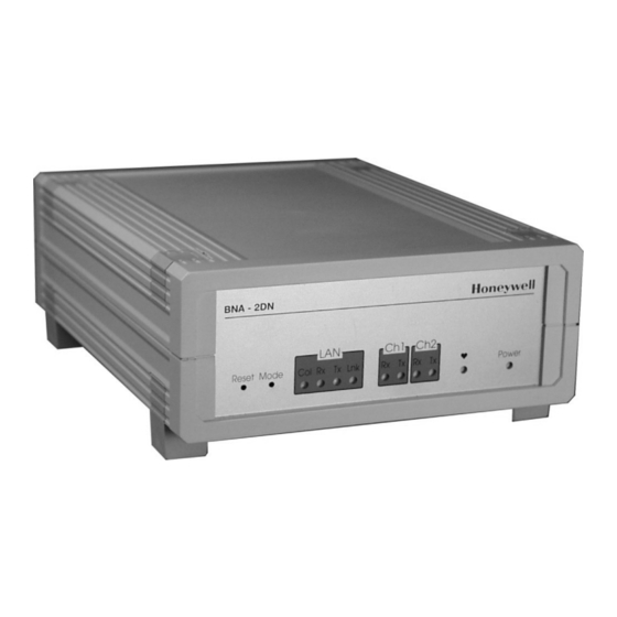
- Page 2 BUILDING NETWORK ADAPTER BNA-1C/2CS/2DN Honeywell BNA - 2DN Honeywell BNA - 2DN Ch1 Ch2 Ch1 Ch2 Reset Mode Col Rx Tx Lnk Power Reset Mode Col Rx Tx Lnk Power Figure 1-1: Parts and Controls on the Front Side Figure 1-2: Parts and Controls on the Rear Side...
-
Page 3: Table Of Contents
BUILDING NETWORK ADAPTER BNA-1C/2CS/2DN Table of Contents About BNA ...5 Location of Parts and Controls ...8 Front Side ...8 Rear Side ...11 Before Installation...13 BNA Operating Positions...15 Single Device ...15 Stacked Devices...16 Wall Mounting ...16 Connections...19 Power Connection...19 Field Bus Connection (Ch1 / Ch2)...20 Bus Termination Switch ...20 L1 Bus Termination...22 BNA Bootloader...23... - Page 4 BUILDING NETWORK ADAPTER BNA-1C/2CS/2DN Cables and Connectors ...42 DB9F Null Modem Cable...42 Ethernet Connectors ...44 7.2.1 RJ45 Connector ...44 7.2.1.1 Connecting a BNA to a Hub...45 7.2.1.2 Connecting a BNA to a Workstation ...46 7.2.2 AUI Connector...47 Tips & Tricks...49 FAQs ...50 Glossary ...51 EN1B-0198GE51 R0801...
-
Page 5: About Bna
Customers can now gain the advantages of high- performance network and services, including traffic management to more locations throughout the network. The Building Network Adapter is using the LAN- connection to provide a seamless communication to EN1B-0198GE51 R0801 Honeywell BNA-2DN L1 Bus meet scalable... - Page 6 Adapter is indicated by LEDs on the front of the device. Technically, Building provides an interface from various Honeywell controller busses that use RS232/RS485 signals to a local area network using 802.3 Ethernet protocol. This allows data to be used by high-level building...
- Page 7 BUILDING NETWORK ADAPTER BNA-1C/2CS/2DN Additionally, each BNA type is equipped with AUI and RJ45 10Base T connectors plus a RS232 interface. EN1B-0198GE51 R0801...
-
Page 8: Location Of Parts And Controls
BUILDING NETWORK ADAPTER BNA-1C/2CS/2DN 2 Location of Parts and Controls The numbering for the parts and controls in this section is referring to the pictures on the rear side of the title page. In order to have a reference between the numbering here and the device pictures, it is possible to fold this page out. - Page 9 BUILDING NETWORK ADAPTER BNA-1C/2CS/2DN Shows the actual LAN traffic using 4 LEDs. Collision indicator If this LED is on, then two or more devices transmitting at the same time. This is not a fault, but a normal occurrence on an Ethernet network. However, when the Collision LED remains on for all transmission attempts, it may indicate an abnormal condition such...
- Page 10 BUILDING NETWORK ADAPTER BNA-1C/2CS/2DN the transceiver shows by itself that it is linked properly to the LAN. Bus Channel 1 activity display. This display contains two green LEDs, one showing the BNA receive activity (Rx) and the other showing the BNA transmit activity (Tx). Bus Channel 2 activity display.
-
Page 11: Rear Side
BUILDING NETWORK ADAPTER BNA-1C/2CS/2DN Rear Side Differences between the various BNA types are explicitly noted in the corresponding element description. 3-pin connector for field bus channel 2 connection electrically isolated meets the EMC-and FCC-requirements. Field Bus wiring is described in chapter 5.2 Field Bus Connection (Ch1 / Ch2) on Page 20. - Page 12 BUILDING NETWORK ADAPTER BNA-1C/2CS/2DN 3-pin connector for field bus channel 1 connection electrically isolated meets the EMC-and FCC-requirements. Field Bus wiring is described in chapter 5.2 Field Bus Connection (Ch1 / Ch2) on Page 20. AC/DC IN 18-24V Power connector for 18-24V AC (50...60Hz) or 18-24V DC power supplies.
-
Page 13: Before Installation
BUILDING NETWORK ADAPTER BNA-1C/2CS/2DN 3 Before Installation Please pay attention to the steps listed below prior to installing the Building Network Adapter device. Verify that the product has been received without damage. Verify that the correct BNA type has been delivered. - Page 14 BUILDING NETWORK ADAPTER BNA-1C/2CS/2DN Pieces Item pole Phoenix channel connectors Optional wall mounting clips Small inserts Screws Please read chapter 5 Connections on page 19 carefully prior to connecting any power and data interface cables to the BNA. Please refer to the installation instruction manuals of each component that shall be connected to the BNA, like 95-7545 XLS1000 Installation...
-
Page 15: Bna Operating Positions
BUILDING NETWORK ADAPTER BNA-1C/2CS/2DN 4 BNA Operating Positions Single Device Figure 4-1: Single device operating position Figure 4-1 shows the normal BNA device operating position e.g. on a desk. EN1B-0198GE51 R0801... -
Page 16: Stacked Devices
BUILDING NETWORK ADAPTER BNA-1C/2CS/2DN Stacked Devices Figure 4-2: Stacked Devices BNA Devices may also be stacked. Because of stability issues, it is recommended not to stack more than 3 devices. Wall Mounting It is also possible to mount the BNA device to a wall. - Page 17 BUILDING NETWORK ADAPTER BNA-1C/2CS/2DN device has to be prepared prior to mounting it to a wall. Put the BNA-adapter with the topside down on the desk (Figure 4-3). Figure 4-3 Remove the four feet (Figure 4-3) from the bottom of the horizontally away from the housing screwdriver (Figure 4-4).
- Page 18 BUILDING NETWORK ADAPTER BNA-1C/2CS/2DN Adjust the four retaining clips (included) on top of the inserts. Fasten the retaining clips with the included four screws (Figure 4-6). Figure 4-6 Use the housing with the clips to mark the positions of the four mounting holes on the wall surface.
-
Page 19: Connections
BUILDING NETWORK ADAPTER BNA-1C/2CS/2DN 5 Connections This chapter describes how to connect power and the field bus to the BNA device. Together with the BNA device, a supply pack with installation material is delivered containing the required connectors for power and field bus. Power Connection For the BNA device an external power supply with the following specification is required:... -
Page 20: Field Bus Connection (Ch1 / Ch2)
BUILDING NETWORK ADAPTER BNA-1C/2CS/2DN Field Bus Connection (Ch1 / Ch2) Regardless of the type of BNA device, the wiring of the field bus connector is always identical. For connecting the field bus, the 3 pole Phoenix connectors (included) are required. Figure 5-1 Figure 5-1 shows the pin layout of the field bus connectors Ch1 and Ch2. - Page 21 BUILDING NETWORK ADAPTER BNA-1C/2CS/2DN For each channel the required termination setting can be adjusted individually. At the rear side of the device, a pictogram (Figure 5-2) symbolizes different terminations. Figure 5-2 normal XD505 compatible bus termination for C- /S- /FS90-Bus connections It is required to use this switch position for S-Bus and FS90-Bus in any case.
-
Page 22: L1 Bus Termination
100 Ω ±5% 0,5 W carbon resistor between each wire and ground. further information regarding termination, please refer to Honeywell DeltaNet R7044 EXCEL PLUS CONTROLLER Application Guide 74-2548, Rev.2/93. EN1B-0198GE51 R0801... -
Page 23: Bna Bootloader
BUILDING NETWORK ADAPTER BNA-1C/2CS/2DN 6 BNA Bootloader This chapter describes the functions of the BNA Bootloader software. Each BNA device is equipped with a Bootloader, which functions in the same way for all BNA device types. N o t e : BNA Devices are not equipped with any application firmware. - Page 24 BUILDING NETWORK ADAPTER BNA-1C/2CS/2DN Start In case of any error heardbeat blinking stops and Initialize Hardware LED will be permanently on Heartbeat LED Blinks for 5 Seconds. Then BNA Download? Download new Firmware to Flash Memory Mode Button pressed? Stay in Bootloader? Firmware in Flash?
-
Page 25: Operating Modes
BUILDING NETWORK ADAPTER BNA-1C/2CS/2DN Operating Modes The BNA Bootloader provides two different operating modes: • Normal Mode • Stay in Bootloader Mode Normal Mode is the default, which directly starts an application firmware found in Flash memory. If no firmware could be found, then the bootloader command shell is started by the BNA (Figure 6-1). - Page 26 BUILDING NETWORK ADAPTER BNA-1C/2CS/2DN Wait till the heartbeat LED starts flashing RED, then press the Mode Button. The heartbeat flashing immediately stops and the LED is permanently on. The operating modes are displayed using the LAN status LEDs Lnk, Tx, Rx. The Normal Mode is represented via the Lnk LED.
- Page 27 BUILDING NETWORK ADAPTER BNA-1C/2CS/2DN Start Press Reset Button Mode Button pressed? Heartbeat blinking stops. LEDs LNK, Tx and Rx are representing current mode. Normal Mode (default) Mode Button pressed? Yes, < 1 sec Yes, < 1sec Stay in Bootloader Mode Mode Button pressed?
-
Page 28: Device Setup
BUILDING NETWORK ADAPTER BNA-1C/2CS/2DN Device Setup In order to setup the BNA device properly, the following connections are necessary: • DB9F Null-Modem cable connected to a PC running a VT100 terminal emulation program or a VT100 compatible terminal (refer to Table 6-1: Terminal settings) •... - Page 29 BUILDING NETWORK ADAPTER BNA-1C/2CS/2DN If this is the very first run of the device, then the Copyright notice is followed by the query for the root user password. At the Old password: prompt just hit the Enter-Key. Once a password has been defined the BNA prints the information User 'root' logged in.
- Page 30 BUILDING NETWORK ADAPTER BNA-1C/2CS/2DN C A U T I O N : Using not-allowed IP-Addresses could cause interference on the network. Please contact your network administrator to retrieve a unique IP-Address. In case you want to connect the BNA to a customer network make sure to get in touch with the customers IT manager to retrieve this IP-Address information.
-
Page 31: Command Description
BUILDING NETWORK ADAPTER BNA-1C/2CS/2DN As mentioned above, the three commands are the minimum required commands for setting up a BNA device. We recommend also performing some user definitions (see command um) for different user roles. Doing so prevents unfamiliar users from performing accidental redefinition of important settings. -
Page 32: Help Or
BUILDING NETWORK ADAPTER BNA-1C/2CS/2DN Text written with this font shows Text terminal output. N o t e : All BNA Bootloader commands are case- sensitive! 6.5.1 Help or ? Entering help or ? at the BNA bootloader> prompt followed bydisplays all available BNA Bootloader commands. -
Page 33: Dc - Download Configuration
Ethernet address (MAC address). So there will be no need for defining a new MAC address. It is recommended to not use this command unless advised to do so by the Honeywell Assistance Center. exit exits the sub-shell and returns to the main shell. - Page 34 BUILDING NETWORK ADAPTER BNA-1C/2CS/2DN application firmware versions when an update of the same becomes necessary. Command dc defines the IP address of the FTP- Server, the path to the application firmware, a username on the FTP-Server and the user’s password. This command must be invoked prior to using command load.
- Page 35 BUILDING NETWORK ADAPTER BNA-1C/2CS/2DN individually. After having entered all requested information it will be asked whether to take over the new settings. If this is denied the old settings will be restored. Otherwise, the new settings are stored to the Flash memory. These settings are immediately active.
-
Page 36: Load - Load Executable
BUILDING NETWORK ADAPTER BNA-1C/2CS/2DN the parameters may be wrong is acceptable. exit exits the sub-shell and returns to the main shell. 6.5.4 load - Load executable The command load is a direct command which immediately starts downloading the application firmware image into the BNA based on the download configuration defined by the command dc. -
Page 37: Ping - Ping
BUILDING NETWORK ADAPTER BNA-1C/2CS/2DN 6.5.5 ping - ping Sends an ICMP Ping through TCP/IP to the FTP- Server defined in the download configuration or to the machine addressed by the IP-Address in the optional command-line parameter. This command can be used to check whether the network connection is working properly. - Page 38 BUILDING NETWORK ADAPTER BNA-1C/2CS/2DN may not be desired that every user will be allowed to do everything with a BNA device. These user accounts are required only for set-up, configuration diagnostic available. The communication protocols allowing the communication between BNA and its building management system are protected at the protocol level depending on the type of application firmware.
- Page 39 BUILDING NETWORK ADAPTER BNA-1C/2CS/2DN user View only rights. Users who are member of this group are not allowed to change or delete any existing definition. priv Privileged rights. Users of the privileged group are allowed to change several definitions like network parameters but they are allowed operations.
-
Page 40: Whoami - Who Am I
BUILDING NETWORK ADAPTER BNA-1C/2CS/2DN delete deletes existing user. The username can optionally be passed directly on the command-line. Furthermore an option –all is available that deletes all user definitions except the one for the root user. The root user account can’t be deleted. - Page 41 BUILDING NETWORK ADAPTER BNA-1C/2CS/2DN using bootloader functionality via a network which can be provided by the application firmware, this command becomes more interesting. EN1B-0198GE51 R0801...
-
Page 42: Cables And Connectors
BUILDING NETWORK ADAPTER BNA-1C/2CS/2DN 7 Cables and Connectors DB9F Null Modem Cable Figure 7-1: Serial connectors The female connector is numbered as shown below: Ground EN1B-0198GE51 R0801... - Page 43 BUILDING NETWORK ADAPTER BNA-1C/2CS/2DN Figure 7-2 shows how to configure a Null Modem Cable DB9F. Figure 7-2: Signal connections for DB9F Null Modem Cable EN1B-0198GE51 R0801...
-
Page 44: Ethernet Connectors
BUILDING NETWORK ADAPTER BNA-1C/2CS/2DN Ethernet Connectors Figure 7-3: BNA Ethernet connectors provides connectors to bring the device online on the LAN. First is a RJ45 10BaseT connector and second is an AUI connector. This chapter describes the pin layout of each connector type and shows how the different cables need to be configured especially for the connection via 10BaseT (RJ45). -
Page 45: Connecting A Bna To A Hub
BUILDING NETWORK ADAPTER BNA-1C/2CS/2DN piece of equipment on the network is connected to a central hub. The wiring is connected to devices using a plug that resembles a phone jack, called RJ45. Pin Number Signal Name Transmit (TX) + Transmit (TX) - Receive (RCV) + Reserved Reserved... -
Page 46: Connecting A Bna To A Workstation
BUILDING NETWORK ADAPTER BNA-1C/2CS/2DN Rx + Rx - Figure 7-4: Straight through pinning for BNA to Ethernet Hub connections 7.2.1.2 Connecting a BNA to a Workstation When a BNA should be directly connected to a workstation without having an Ethernet Hub in between a special cable, called crossover cable, is required. -
Page 47: Aui Connector
BUILDING NETWORK ADAPTER BNA-1C/2CS/2DN Rx + Rx - Figure 7-5: Crossover pinning for BNA to workstation direct- connections 7.2.2 AUI Connector The AUI (Attachment Unit Interface) offers an alternative way of connecting the BNA device to the Ethernet regardless which Ethernet medium or technique it uses. - Page 48 BUILDING NETWORK ADAPTER BNA-1C/2CS/2DN Nowadays the AUI is used to connect a small device called transceiver, which adapts between the AUI on the device and the Ethernet medium used in the current installation. 1. Coll. shield 9. Coll. presence - 2.
-
Page 49: Tips & Tricks
BUILDING NETWORK ADAPTER BNA-1C/2CS/2DN Tips & Tricks Tip 1 To simplify downloading, we re- commend reducing (renaming) the application firmware image name to the base name of the image in the FTP- Server publication rename bna_susi_server_v1.0.0.bin bna_susi_server.bin. This has the advantage that even when updates or upgrades of the application firmware are delivered, no change is necessary in each BNA download... -
Page 50: Faqs
BUILDING NETWORK ADAPTER BNA-1C/2CS/2DN FAQs 1. Which terminal type can be used for connecting to the BNA Bootloader? For connecting to the BNA Bootloader, any VT100 compatible terminal compatible terminal emulation program can be used. For the proper terminal settings, please refer to chapter 6.4 Device Setup on Page 28. -
Page 51: Glossary
BUILDING NETWORK ADAPTER BNA-1C/2CS/2DN Glossary 10BaseT 10 = 10Mbps, Base = baseband, T = twisted pair. Application firmware An application firmware is a software that is needed to operate the BNA device Management System requires it. An example for an application firmware is the BNA SUSI Server software. - Page 52 BUILDING NETWORK ADAPTER BNA-1C/2CS/2DN Transmission Control Protocol Wide Area Network XD505 C-Bus piggyback controllers. Compatible with EXCEL IRC devices on the same bus. XD508 C-Bus piggyback controllers. This piggyback type allows C-Bus communication transfer rates up to 76.8 kbps. This piggyback type allows C-Bus wiring...
- Page 54 BUILDING NETWORK ADAPTER BNA-1C/2CS/2DN Honeywell Honeywell Regelsysteme GmbH Honeywellstr. 2-6 D-63477 Maintal Tel. (49) 6181 401-1 Fax (49) 6181 401-400 http://europe.hbc.honeywell.com Subject to change without notice. Printed in Germany. Manufacturing location certified to EN ISO 9001 EN1B-0198GE51 R0801...