Quick Links
29490
I
NTRODUCTION
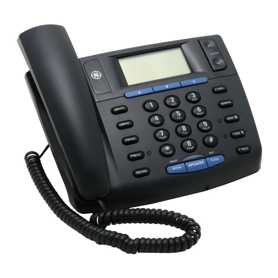
Two Line Caller ID Speakerphone
with 13 Number Memory
CAUTION: When using telephone equipment, there are
basic safety instructions that should always be followed. Refer
User's Guide
to the IMPORTANT SAFETY INSTRUCTIONS provided with
this product and save them for future reference.
Your Caller ID phone stores and displays specific information,
provided by your local telephone company, to subscribers of
Caller ID or similar caller identification services.
Your Caller ID phone enables you to:
• Identify callers before you answer the phone.
• View the time and date of each incoming call.
• Record up to 75 Caller ID messages sequentially.
IMPORTANT: In order to use all of the features of this telephone,
you must subscribe to two separate services available from your
local telephone company: the standard Name/Number Caller ID
Service to know who is calling when the phone rings and Caller ID
with Call Waiting Service to know who is calling while you are on
the phone.
S
HORT
M
THIS
Hook switch. The part of the phone that pops up to activate
the phone line when the handset is lifted from the base.
Off-hook. A term used to describe the phone in its active
mode when the handset is off of the base cradle or when the
We bring good things to life.
SPEAKER button is pressed.
On-hook. A term used to describe the phone in an inactive
mode.
I
I
MPORTANT
NFORMATION
B
NOTICE: This product meets the applicable Industry Canada
EFORE
technical specifications.
P
C
The equipment must be installed using an acceptable method of
ARTS
connection. The customer should be aware that compliance with
Make sure your package includes the following items:
the above conditions may not prevent degradation of service in
some situations.
Repairs to certified equipment should be made by an authorized
A
B
C
DELETE
MENU
Canadian maintenance facility designated by the supplier. Any
STORE
MUTE
VOLUME
PAUSE
EXIT
REDIAL
SPEAKER
FLASH
repairs or alterations made by the user to this equipment, or
Base
equipment malfunctions, may give the telecommunications
company cause to request the user to disconnect the equipment.
Users should ensure for their own protection that the electrical
ground connections of the power utility, telephone lines and
M
internal metallic water pipe systems, if present, are connected
ODULAR
together. This precaution may be particularly important in rural
To properly connect your phone to your telephone lines, you
areas.
should identify the type of wall jack(s) you have. You will need
CAUTION: Users should not attempt to make such connections
an RJ11C (for a single line) or a RJ14C (for two lines) type
themselves, but should contact the appropriate electric inspection
modular phone jack, which might look
authority, or electrician, as appropriate.
like the one pictured here. If you don't
NOTES: This equipment may not be used on coin service provided
have either modular jack, call your local
by the telephone company.
phone company to find out how to get
I
I
one installed.
NTERFERENCE
NFORMATION
I
This equipment generates and uses radio frequency energy which
NSTALLATION
may interfere with residential radio and television reception if not
properly installed and used in accordance with instructions
contained in this manual. Reasonable protection against such
DELETE(button)
interference is ensured, although there is no guarantee this will not
occur in a given installation. If interference is suspected and
MENU(button)
verified by switching this equipment on and off, the user is
encouraged to try to correct the interference by one or more of the
STORE
following measures: Reorient the radio/television receiver's
(button)
antenna, relocate the equipment with respect to the receiver, plug
the equipment and receiver into separate circuit outlets. The user
MUTE
may also wish to consult a qualified radio/television technician for
(indicator)
additional suggestions. This equipment has been fully tested and
MUTE
complies with all limits for Class B computing devices pursuant to
(button)
part 15 FCC Rules and Regulations. This apparatus does not exceed
VOLUME
the class B limits for RF noise emissions specified in the RFI
(button)
regulations of the Industry Canada.
H
A
C
(HAC)
REDIAL/PAUSE
EARING
ID
OMPATIBILITY
(button)
This telephone system meets FCC/Industry Canada standards for Hearing Aid
SPEAKER (indicator)
Compatibility.
REN NUMBER IS LOCATED ON THE CABINET BOTTOM
CAUTION: Disconnect the phone cord from the wall outlet
CAUTION:
RISK OF ELECTRIC SHOCK
before installing or replacing the batteries.
DO NOT OPEN
THE LIGHTNING
CAUTION: TO REDUCE THE
THE EXCLAMATION
FLASH AND ARROW
RISK OF ELECTRIC SHOCK, DO
POINT WITHIN THE
WARNING: TO
I
MPORTANT
HEAD WITHIN THE
NOT REMOVE COVER (OR
TRIANGLE IS A
PREVENT FIRE OR
WARNING SIGN
TRIANGLE IS A
BACK). NO USER
WARNING SIGN
SERVICEABLE PARTS INSIDE.
ALERTING YOU OF
ELECTRICAL SHOCK
• Never install telephone wiring during a lightning storm.
ALERTING YOU OF
REFER SERVICING TO
IMPORTANT
HAZARD, DO NOT
"DANGEROUS
QUALIFIED SERVICE
INSTRUCTIONS
VOLTAGE" INSIDE
PERSONNEL.
ACCOMPANYING
EXPOSE THIS
• Never touch uninsulated telephone wires or terminals,
THE PRODUCT.
THE PRODUCT.
PRODUCT TO RAIN
SEE MARKING ON BOTTOM / BACK OF PRODUCT
unless the telephone line has been disconnected at the
OR MOISTURE.
network interface.
• Use caution when installing or modifying telephone lines.
• Never install telephone jacks in wet locations unless the
jack is specifically designed for wet locations.
• Temporarily disconnect any equipment connected to the
Model 29490
ATLINKS Communications Canada Inc.
phone, such as faxes, other phones, or modems.
00002010 (Rev. 2 E)
© 2004 ATLINKS Communications Canada, Inc.
04-51
Trademark(s) ® Registered
Printed in China
Marque(s) ® déposée(s)
I
NSTALLING AND
Your Caller ID phone uses 4 AA-size alkaline batteries for
receiving and storing Caller ID records and for storing the
numbers you use for memory dialing, pulse dialing, and redial.
IMPORTANT: You will have approximately 90 seconds to replace
the batteries before the memories stored are lost. Please read the
instructions before replacing the batteries and have the batteries
ready to be inserted beforehand.
IMPORTANT: If you are not going to use the telephone for more
than 30 days, remove the batteries because they may leak and
damage the unit.
1. Press down and out on the snap
tab located on the top of the
mounting bracket. Lift the bracket
off.
2. Release latch on battery
compartment and remove cover.
3. Insert 4 AA-size alkaline batteries
as shown on the diagram in the battery compartment.
4. Snap the battery compartment door back into place and
G
T
U
LOSSARY OF
ERMINOLOGY
SED IN
replace the mounting bracket.
ANUAL
5. If the line cord was previously connected, re-attach it to
the unit and check your memory locations.
NOTE: If the low battery icon appears in the display, you need to
replace the batteries. It is important that you replace the batteries as
soon as possible in order to maintain Caller ID operation.
I
NSTALLATION
D
I
ESKTOP
NSTALLATION
Y
B
OU
EGIN
HECKLIST
REVIEW
DIAL
CONFER
LINE
2
LINE
1
HOLD
A coiled handset cord and two straight telephone line cords
Desktop/wall
4-wire
Handset Handset
mounting
telephone
are packaged with your unit. Your two-line phone should be
cord
pedestal
line cord
placed on a level surface such as a tabletop or desk.
To attach the desktop pedestal:
J
R
ACK
EQUIREMENTS
• Turn the phone over so that the bottom of the base is facing
up and the thickest end is facing away from you.
• With the rounded end of the wedge pointing downward,
insert the tab on the rounded end of the pedestal into the
upper middle slot on the bottom of the base, then push the
Wall plate
pedestal down until the two tabs on the left and right
Modular
corners of the pedestal snap (lock) into the two upper slots
telephone
on the bottom of the base.
line jack
To connect LINES 1 + 2:
& S
ETUP
There are two possible connections.
Refer to Figure 1 if you have one single line (RJ11C)
Quick dial/emergency
display
phone jack or one dual-line (RJ14C) phone jack.
memory (buttons)
REVIEW (button)
1. Connect one end of either straight telephone line cord to
the jack marked LINE 1+2 on the back of the base.
DIAL (button)
2. Connect the other end to the single-line or dual-line wall
CONFER
phone jack.
REVIEW
(conference
button)
FIGURE 1
A
B
C
DELETE
DIAL
LINE 2
One dual-line jack or
MENU
CONFER
(indicator)
one single-line wall
STORE
LINE
2
MUTE
LINE
1
phone jack
LINE 2
PAUSE
EXIT
HOLD
VOLUME
REDIAL
SPEAKER
FLASH
(button)
LINE 1
(button)
LINE 1
(indicator)
HOLD (button)
NOTE: If you connect the telephone line cord to the single-
FLASH/EXIT (button)
line (RJ11C) wall phone jack, you will only be able to use one
SPEAKER (button)
telephone line (either LINE 1 or LINE 2) but not both lines
simultaneously.
Refer to Figure 2 if you have two single-line (RJ11C)
phone jacks.
I
I
NSTALLATION
NFORMATION
1. Connect one end of either straight telephone line cord to
the jack marked LINE 1+2 on the back of the base.
2. Connect one end of the other straight telephone line cord to
the jack marked LINE 2 on the back of the base.
3.Connect the other end of each straight telephone line
cord to the two single line wall phone jack.
4. Plug one end of the coiled handset cord into the handset and
the opposite end into the base.
5. Set the RINGER LINE 1 and RINGER LINE 2 volume switches
located at the back of the base to the desired loudness.
OFF - Telephone will not ring.
R
B
EPLACING THE
ATTERIES
LO - Sound will be lowest.
HI
- Sound will be loudest.
6. Press the LINE 1 button if the LINE 1 telephone cord is
connected. Otherwise, press LINE 2.
7. The unit is properly installed if you pick up the handset and
hear the dial tone. Otherwise, recheck all installation steps.
W
M
I
ALL
OUNT
NSTALLATION
Your speakerphone can also be mounted on a wall plate (not
included).
To attach the wall mounting pedestal:
• Turn the phone over so that the bottom of the base is facing
up and the thickest end is pointing away from you.
• With the rounded end of the pedestal pointing upward,
insert the tab on the end of the pedestal into the lower
middle slot on the bottom of the base, then push the
pedestal down until the two tabs on the left and right
corners of the pedestal snap (lock) into the two lower slots
on the bottom of the base.
To connect LINES 1 + 2:
There are two possible connections.
Refer to Figure 1 at beginning of Installation section
if you have one single line (RJ11C) phone jack or
REVIEW
one dual-line (RJ14C) phone jack.
A
B
C
DELETE
DIAL
1. Connect one end of either straight telephone line cord to
MENU
CONFER
STORE
LINE
2
the jack marked LINE 1+2 on the back of the base.
MUTE
LINE
1
PAUSE
EXIT
HOLD
VOLUME
REDIAL
SPEAKER
FLASH
2.Connect the other end to the single-line or dual-line wall
phone jack.
NOTE: If you connect the telephone line cord to the single-line
(RJ11C) wall phone jack, you will only be able to use one telephone
line (either LINE 1 or LINE 2) but not both lines simultaneously.
Refer to Figure 2 at beginning of Installation section
if you have two single-line (RJ11C) phone jacks.
1. Connect one end of either straight telephone line cord to
the jack marked LINE 1+2 on the back of the base.
2. Connect one end of the other straight telephone line cord to
the jack marked LINE 2 on the back of the base.
3.Connect the other end of each straight telephone line
cord to the two single line wall phone jack.
NOTE : If desired, gather the extra telephone line cord together
and store inside the wall mounting bracket.
4. Slip the mounting holes over the wall plate posts and firmly
slide the unit down into place (wall plate not included).
5. Plug one end of the coiled handset cord into the handset and
the opposite end into the base.
6. Set the RINGER LINE 1 and RINGER LINE 2 volume switches
located at the back of the base to the desired loudness.
OFF - Telephone will not ring.
LO - Sound will be lowest.
HI
- Sound will be loudest.
FIGURE 2
7. Press the Line 1 button if the Line 1 telephone cord is
Two single-
line wall
connected. Otherwise, press the Line 2 button.
phone jacks
8. The unit is properly installed if you pick up the handset and
hear the dial tone. Otherwise, recheck all installation steps.
D
P
ATA
ORT
This phone is equipped with a LINE2 jack for you to connect an
auxiliary phone device, such as a fax machine, computer
modem, answering machine, or even a cordless phone. You can
install the phone as described in "Two Lines on a Single Modular
Jack", then you can use the LINE2 jack to connect your fax
machine and receive faxes on the phone number for line 2.
S
U
C
ETTING
P THE
ALLER
You should not plug the telephone into the modular jack while
setting up the Caller ID menu.
1. Press the MENU button to enter the menu feature
configuration mode.
# 1. >ENG FRA ESP (CID language default English)
# 2. CONTRAST (default level is 3).
# 3. LOCAL AREA CODE
# 4. TONE/PULSE (Default is tone dialing).
2. Press the MENU button to scroll through the 4 menu screens.
3. Use the REVIEW
^
or V buttons to select the desired setting.
NOTE: You have 20 seconds following an entry before the phone
returns to the Summary Screen.
S
Y
L
A
C
ETTING
OUR
OCAL
REA
ODE
The telephone uses the programmed area codes to determine
the number format to display when a valid Caller ID signal is
received. Numbers that match the local area code are displayed
as seven digits and are used for dialing back previous numbers.
Entering your local area code will also help you immediately
know if the call is local or long distance when viewing the CID
records in the display.
NOTE: If you make a mistake and want to start over again, press
REVIEW
the DELETE button to delete all of the digits.
A
B
C
DELETE
DIAL
MENU
CONFER
1. Press the MENU button until LOCAL AREA CODE shows in
STORE
LINE
2
MUTE
1
LINE
PAUSE
EXIT
HOLD
the display.
VOLUME
REDIAL
SPEAKER
FLASH
2. Press the REVIEW
^
button to enter the second
and third digit.
3. Press the REVIEW V button to enter digit.
4. Press the MENU button to save.
S
D
L
ETTING THE
ISPLAY
ANGUAGE
This adjustment changes the Caller ID prompts to be
displayed in English, French, or Spanish.
1. Press the MENU button until ENG FRA ESP shows in the
display.
2. Use the REVIEW
^
or V button to select ENG, FRA or ESP .
3. Press the MENU button to save.
S
C
ETTING THE
ONTRAST
This adjustment allows you to adjust the contrast of the
display.
1. Press the MENU button until CONTRAST shows in the
display.
^
2. Use the REVIEW
or V button to select level 1,2,3,4, or 5 .
3. Press the MENU button to save.
S
D
M
ETTING THE
IAL
ODE
This adjustment allows you to select tone (touch-tone) or
pulse (rotary) dialing.
1. Press the MENU button until TONE/PULSE MODE shows in
the display.
^
2. Press the REVIEW
or V button to show the current dialing
mode. The default is TONE dialing.
3. To change the dialing mode, press the review key. The
display alternates between the two modes.
4. Press the MENU button to save.
NOTE: The phone will exit set up after 20 seconds if no buttons
are pressed.
REMINDER: The time and date are programmed automatically
when the first Caller ID record is successfully received after set up.
C
ID F
ALLER
EATURES
S
S
UMMARY
CREEN
The Summary Screen shows the current time, date, and
number of new calls to review. It is displayed until any button
is pressed.
NOTE: The number of new calls is displayed until all new calls
have been reviewed.
R
S
C
ECEIVING AND
TORING
ALLS
This unit receives and displays information transmitted by
your local phone company. This information can include the
phone number, date, and time; or the name, phone number,
date, and time. The unit can store up to 75 calls for later
review. When the memory is full, a new call automatically
replaces the oldest call in memory. NEW appears in the
display for calls received that have not been reviewed.
R
C
R
EVIEWING
ALL
ECORDS
^
• Press the REVIEW
or V button to view the call records.
ID M
ENU
• Press the REVIEW
^
button to scroll through the call
records from the most recent to the oldest.
• Press the REVIEW V button to scroll through the call
records from the oldest to the newest.
• When all of the records have been viewed, START/END
appears in the display.
D
C
R
ELETING
ALL
ECORDS
• To delete the record shown in the display, press the DELETE
button once.
• To delete all records while reviewing, press and hold the
DELETE button for about three seconds. DELETE ALL?
appears in the display. Press DELETE again to complete.
D
B
IALING
ACK
When reviewing Caller ID records, you can dialback the
numbers shown on the display by pressing the DIAL button.
NOTE: If PICKUP PHONE shows in the display, no other changes
to the number can be made. The information sent from the
telephone company is known to be a valid number for dialing back
(used only in very limited areas). Once you pickup the phone, the
number is automatically dialed.
NOTE: Make sure either line button 1 or 2 is pressed, when the
handset is picked-up or the speakerphone is in use.
I
Y
P
Y
L
A
C
I
F
OU
ROGRAMMED
OUR
OCAL
REA
ODE
N
S
U
M
THE
ET
P
ENU
^
1. Use the REVIEW
or V button to display the number you
want to dial.
2. Press the DIAL button.
• If you see a number with seven digits (i.e. 555-1234), then
the call is from within your area code. However, this does
not guarantee the call is a local call.
• If you see a number with 11 digits (i.e. 1-234-555-1234), then
the call is not from within your area code.
NOTE: A timer (10 seconds on-hook and 3 seconds off-hook)
located in the upper right side of the display will start, letting
you know how much time is left until the unit returns to the
Summary Screen.
3. If you are at on-hook and " PICKUP OR ADJ " displays, you can
adjust the phone number format by pressing the DIAL button. If
the phone is off-hook and " ADJUST " shows in the display, you
can adjust the phone number format by pressing the DIAL
button. For example, sometimes a 7-digit local number cannot
be dialed because it requires a 10-digit or 11-digit format.
Press the DIAL button repeatedly to scroll through the 7, 10,
and 11-digit numbers.
7-digits:
7-digit telephone number (i.e. 555-5555)
10-digits:
3-digit area code + 7-digit telephone number
(i.e. 425-555-5555)
11-digits:
long distance code 1 + 3-digit area code +
7-digit telephone number (i.e. 1-425-555-5555)
4. To dial the displayed number, and the phone is on-hook,
pick up the handset or press the SPEAKER button before
the timer reaches 0. If the phone is off-hook, wait until the
time reaches 0. NOW DIALING shows in the display and the
number is dialed.
NOTE: Make sure either the 1 or 2 line button is pressed.
I
Y
D
N
P
Y
L
A
F
OU
ID
OT
ROGRAM
OUR
OCAL
REA
C
I
S
U
M
ODE
N THE
ET
P
ENU
^
1. Use the REVIEW
or V buttons to display the number you
want to dial. You will only see 10-digit numbers (i.e. 234-
555-1234).
2. See steps 2 through 4 in the previous section to
complete the dialback process.
C
ID D
M
ALLER
ISPLAY
ESSAGES
The following special messages indicate the status of a message or
the unit:
BLOCKED CALL
The caller of the incoming call is
registered as "Private Number" and
their Caller ID information is withheld.
CALL WAITING
Indicates a call is waiting on the line.
Battery power level is low.
NO CALLS
The caller memory is empty.
START/END
You are at the beginning or the end of the
Caller ID memory log.
UNKNOWN
The incoming call does not have Caller ID
CALLER
service or their service area is not linked
to yours. If UNKNOWN CALLER
appears along with a calling number, the
name information for that number was
not available.
S
B
PEAKERPHONE
ASICS
S
L
PEAKERPHONE
OCATION
Your phone features a speakerphone for ease of use and
convenience during a phone conversation. At any time during
a conversation, you can lift the handset to stop using the
speakerphone. Likewise, when you are using the handset,
press the SPEAKER button and place the handset in the
cradle to switch to the speakerphone.
For best speakerphone performance, avoid the following:
• Areas with high background noise. (The microphone might
pick up these sounds and prevent the speakerphone from
going into the receiving mode when you finish talking.)
• Surfaces affected by vibration.

Related Manuals for GE 2010


Summary of Contents for GE 2010
- Page 1 - Sound will be loudest. numbers you use for memory dialing, pulse dialing, and redial. 6. Press the LINE 1 button if the LINE 1 telephone cord is IMPORTANT: You will have approximately 90 seconds to replace connected. Otherwise, press LINE 2.
- Page 2 DELETE button. Chain dialing allows you to dial a sequence of stored numbers 4. Use the number keys to enter the telephone number (up to from separate memory locations. 32 digits) and press the STORE button to save. (The unit will For example not dial a phone number in this mode.) The cursor...