Honeywell VISTA-128BPTSIA User Manual
Commercial burglary partitioned security system with scheduling
Hide thumbs
Also See for VISTA-128BPTSIA:
- Quick manual (2 pages) ,
- Installation and setup manual (124 pages) ,
- Programming manual (105 pages)
Table of Contents
Quick Links
800-06905 6/10 Rev C
V V V V
V V V V
V V V V
V V V V
V V V V
I I I I
S S S S
T T T T
V V V V
I I I I
S S S S
T T T T
C C C C
o o o o
C C C C
o o o o
P P P P
a a a a
r r r r
t t t t
i i i i
t t t t
i i i i
o o o o
n n n n
e e e e
P P P P
a a a a
r r r r
t t t t
i i i i
t t t t
i i i i
o o o o
n n n n
e e e e
I I I I
S S S S
T T T T
A A A A
- - - -
1 1 1 1
I I I I
S S S S
T T T T
A A A A
- - - -
1 1 1 1
I I I I
S S S S
T T T T
A A A A
- - - -
2 2 2 2
I I I I
S S S S
T T T T
A A A A
- - - -
2 2 2 2
A A A A
- - - -
1 1 1 1
2 2 2 2
8 8 8 8
B B B B
A A A A
- - - -
1 1 1 1
2 2 2 2
8 8 8 8
B B B B
m m m m
m m m m
e e e e
r r r r
c c c c
i i i i
a a a a
m m m m
m m m m
e e e e
r r r r
c c c c
i i i i
a a a a
d d d d
S S S S
e e e e
c c c c
u u u u
r r r r
i i i i
d d d d
S S S S
e e e e
c c c c
u u u u
r r r r
i i i i
W W W W
i i i i
t t t t
h h h h
S S S S
c c c c
W W W W
i i i i
t t t t
h h h h
S S S S
U U U U
U U U U
2 2 2 2
8 8 8 8
B B B B
P P P P
T T T T
2 2 2 2
8 8 8 8
B B B B
P P P P
T T T T
5 5 5 5
0 0 0 0
B B B B
P P P P
T T T T
5 5 5 5
0 0 0 0
B B B B
P P P P
T T T T
P P P P
T T T T
S S S S
I I I I
A A A A
P P P P
T T T T
S S S S
I I I I
A A A A
l l l l
B B B B
u u u u
r r r r
g g g g
l l l l
a a a a
r r r r
y y y y
l l l l
B B B B
u u u u
r r r r
g g g g
l l l l
a a a a
r r r r
y y y y
t t t t
y y y y
S S S S
y y y y
s s s s
t t t t
e e e e
m m m m
t t t t
y y y y
S S S S
y y y y
s s s s
t t t t
e e e e
m m m m
h h h h
e e e e
d d d d
u u u u
l l l l
i i i i
n n n n
g g g g
c c c c
h h h h
e e e e
d d d d
u u u u
l l l l
i i i i
n n n n
g g g g
s s s s
e e e e
r r r r
G G G G
u u u u
i i i i
d d d d
e e e e
s s s s
e e e e
r r r r
G G G G
u u u u
i i i i
d d d d
e e e e
/ / / /
/ / / /
/ / / /
/ / / /
Table of Contents

Related Manuals for Honeywell VISTA-128BPTSIA


Summary of Contents for Honeywell VISTA-128BPTSIA
- Page 1 V V V V I I I I S S S S T T T T A A A A - - - - 1 1 1 1 2 2 2 2 8 8 8 8 B B B B P P P P T T T T / / / /...
- Page 2 Your Honeywell security system is designed for use with devices manufactured or approved by Honeywell for use with your security system. Your Honeywell security system is not designed for use with any device that may be attached to your security system's keypad or other communicating bus if Honeywell has not approved such device for use with your security system.
-
Page 3: Table Of Contents
TABLE OF CONTENTS SYSTEM OVERVIEW ........5 Common Lobby Operation .......25 General ............5 How User Codes Affect the Common A Partitioned System ........6 Lobby ............26 Zones ............6 CHECKING FOR OPEN ZONES ....27 Fire Protection ..........6 Using the ✳ READY Key ......27 Carbon Monoxide Protection ......6 DISPLAYING ALL ZONE Alarms............6... - Page 4 TESTING THE SYSTEM (TO BE Using the 9 Key ........41 CONDUCTED WEEKLY) ......60 VIEWING ALARM COMPANY Using the 5 TEST Key ......60 MESSAGES ..........42 General Information........42 Testing Your System ........ 60 PANIC KEYS..........43 FIRE ALARM SYSTEM........ 61 (FOR MANUALLY ACTIVATING SILENT In Case Of Fire Alarm.......
-
Page 5: System Overview
System Overview General Your Honeywell security system consists of a main control panel, at least one keypad, and various sensors strategically positioned throughout the premises. The system offers you three forms of protection: burglary, fire and emergency. The keypad provides full control of system operation. -
Page 6: A Partitioned System
System Overview (cont’d) A Partitioned System Simply stated, a partitioned system shares one physical alarm system among different users, each with their own requirements. For the most part, you as a user need not know about other users and their structure in the system, but from time to time, you may see display messages that indicate the system is in use by another user. -
Page 7: Burglary Protection
System Overview (cont’d) NOTE: Cross Zoning and Swinger Suppression options can help reduce false alarms. Ask your installer if your system is programmed for either of these features. An Abort Window feature exists for all non-fire zones. All non-fire alarm reports are NOT transmitted to the central station if the code + off sequence is entered within the Abort Window time period. -
Page 8: Speed Key (Macros)
System Overview (cont’d) Speed Key (Macros) The system can store a string of up to 32 keystrokes, which can be activated anytime by simply pressing the “A, B, C, or D” keys. This feature can be used to make it easy to perform multiple functions at once (such as going to another partition to bypass a zone), or it can be used to simplify an everyday, repeated procedure. -
Page 9: Self-Help Feature
System Overview (cont’d) Self-Help Feature Abbreviated user's instructions are built into the system that can be easily viewed on the alpha keypad's message display screen. This feature will prove particularly useful if this manual is not conveniently accessible when you need to perform a system procedure with which you are not familiar. -
Page 10: About The Keypads
About The Keypads General IMPORTANT: If the keypad beeps rapidly upon entering the premises, it indicates that an alarm has occurred during your absence. LEAVE IMMEDIATELY and CONTACT THE POLICE from a safe location nearby. NOTE: If you have a Touch Screen Keypad connected to your system, refer to the Touch Screen Keypad User Guide for operating instructions. -
Page 11: Functions Of The Keypad
Functions of the Keypad DISPLAY SPEAKER ARMED AWAY STAY LEDS READY TEST BYPASS INSTANT CODE CHIME READY FUNCTION KEYS IMPORTANT! When using the keypad to enter codes and commands, sequential key depressions must be made within 3 seconds of one another. - Page 12 Functions of the Keypad (cont’d) PERIMETER ONLY for a full explanation ALPHA DISPLAY WINDOW: A 2-line, of the STAY key. 32-character Liquid Crystal Display (LCD) that displays protection point identification 4 MAXIMUM : Arms in manner similar and system status, messages, and user to AWAY mode, but eliminates the entry instructions.
- Page 13 Functions of the Keypad (cont’d) KEYS 0-9: Used to enter your individual 9 CHIME : Turns on & off the CHIME security access code(s). mode. When on, any entry through a LED READY INDICATOR: (GREEN) Lit protected delay or perimeter zone while the indicates system is ready to be armed, system is disarmed will cause a tone to while unlit indicates system not ready.
-
Page 14: Entry/Exit Delays
Entry/Exit Delays General Information Your system has installer-programmed time delays, known as exit delay and entry delay. Whenever you arm your system, exit delay gives you time to leave through the designated exit door without setting off an alarm. Exit delay begins immediately after entering any arming command, and applies to all modes of arming protection. -
Page 15: Security Codes And Authority Levels
Security Codes and Authority Levels General Information At the time of installation, you were assigned an authority level and a personal four-digit security code, known only to you and yours. The security code must be entered when arming and disarming the system. The authority level defines the system functions that you can perform. -
Page 16: Authority Levels
Security Codes and Authority Levels (cont’d) Authority Levels Authority levels define the system functions a particular user can perform. Depending on the authority assigned to you, there are certain system functions you may be prohibited from performing. In summary, there are six authority levels, each having certain system restrictions as shown below. -
Page 17: General Rules On Authority Levels And Changes
Security Codes and Authority Levels (cont’d) General Rules on Authority Levels and Changes • A user may not delete or change the user code of the SAME or HIGHER authority than which he is assigned. • A user may only ADD users to a LOWER authority level. •... -
Page 18: To Add A User
Security Codes and Authority Levels (cont’d) To Add a User IMPORTANT: Temporary users should not be shown how to use any system function they do not need to know (e.g. bypassing protection zones). CODE 1. Enter Master or Manager code and press the key. - Page 19 Security Codes and Authority Levels (cont’d) If you as a user have access to other partitions, the MULTI-ACCESS ? keypad will prompt for ability of this new user to 0 = NO , 1 = YES access (GOTO) those partitions. Press 0 (NO) or 1 (YES).
-
Page 20: To Change A User's Code
Security Codes and Authority Levels (cont’d) To Change a User's Code CODE 1. Enter Master or Manager code and press the key + user number to be changed. 2. Enter the new code for that user. The system will recognize that the user number is ADD NEW USER? already in use and will prompt whether or not this 0 = NO , 1 = YES... -
Page 21: To Delete A User
Security Codes and Authority Levels (cont’d) To Delete a User CODE 1. Enter Master or Manager code and press the key + user number to be deleted. 2. Enter Master or Manager code first entered. The system will recognize that the User number OK TO DELETE is already in use and will prompt to confirm that 0 = NO , 1 = YES... -
Page 22: Accessing Other Partitions
Accessing Other Partitions To Access another Partition Each keypad is assigned a default partition for display purposes, and will show only that partition's information. But, if the user is authorized, a keypad in one partition can be used to perform system functions in other partitions by using the GOTO command. -
Page 23: Master Keypad Operation
Accessing Other Partitions (cont’d) Global Arming Notes: • When performing a Global Arm, if there are faults in any of the selected partitions, the system will enter a Summary Mode. Faulted zones in all the selected partitions will be displayed. These faults must be corrected or bypassed. - Page 24 Accessing Other Partitions (cont’d) The following is an example of what would be displayed for a fault condition on Zone 002 (Loading Dock Window) on Partition 1 (Warehouse) when logging on from a keypad on Partition 9: WHSE DISARMED HIT ∗ FOR FAULTS This is the normal display that appears at Partition 1's keypad(s).
-
Page 25: Common Lobby Operation
Accessing Other Partitions (cont’d) Common Lobby Operation When an installation consists of a partition that is shared by users of other partitions in a building, the shared partition may be assigned as a “common lobby” partition for the system. An example of this might be in a medical building where there are two doctors and a common entrance area. -
Page 26: How User Codes Affect The Common Lobby
Accessing Other Partitions (cont’d) How User Codes Affect the Common Lobby Codes with “Global” Arming If your code is given “global arming” when it is defined, the system displays a prompt that allows you to pick and choose the partitions to be armed or disarmed. -
Page 27: Checking For Open Zones
Checking For Open Zones Using the ✳ ✳ ✳ ✳ READY Key Before arming your system, all protected doors, windows and other protection zones must be closed or bypassed (see BYPASSING section). Otherwise the keypad will display a "Not Ready" message. Using the READY key will display all zones that are faulted, making it easier for you to secure any open zones. -
Page 28: Displaying All Zone Descriptors
Displaying All Zone Descriptors Using the ✳ ✳ ✳ ✳ READY Key The Alpha Keypads can also display all the zone descriptors that are programmed in your system. The abbreviated instructions for the READY key will appear first, followed by the zone descriptors. Displaying all descriptors is useful when you need to know the zone number of a particular zone, as when bypassing zones. -
Page 29: Bypassing Protection Zones
Bypassing Protection Zones Using the 6 BYPASS Key This key is used when you want to arm your system with one or more zones intentionally unprotected. Bypassed zones are unprotected and will not cause an alarm when violated while your system is armed. All bypasses are removed when an OFF sequence (security code plus OFF) is performed. -
Page 30: Quick Bypass
Bypassing Protection Zones (cont’d) Quick Bypass Your system allows you to easily bypass all open (faulted) zones without having to enter zone numbers individually. NOTE: All bypasses are removed when an OFF sequence (security code plus OFF) is performed. To use the Quick Bypass feature: BYPASS 1. -
Page 31: Group Bypass
Bypassing Protection Zones (cont’d) Group Bypass Your system allows you to easily bypass a group of zones without having to enter zone numbers individually. The system provides up to 15 groups. There is no limit to the number of zones that may be assigned to any one group. Check with your installer for a list of zones assigned to the group(s). -
Page 32: Zones Remaining Bypassed After Disarming
Bypassing Protection Zones (cont’d) Zones Remaining Bypassed After Disarming The system provides an option to allow all manually bypassed zones to remain bypassed upon disarming (security code + OFF) of the partition. This option must be programmed by your installer. Check with your installer to see if this option has been enabled. -
Page 33: Arming Perimeter Only
Arming Perimeter Only (With Entry Delay ON) Using the 3 STAY key Use this key when you are staying home, but might expect someone to use the entrance door later. When armed in STAY mode, the system will sound an alarm if a protected door or window is opened, but you may otherwise move freely throughout the premises. -
Page 34: Auto-Stay Arming
Arming Perimeter Only (With Entry Delay ON) (cont’d) Auto-STAY Arming Auto-stay allows the system to automatically bypass certain zones if upon arming none of the entry/exit zones are faulted during the exit delay time (no one exits the premises). The system provides an option to set each burglary zone for Auto-stay. -
Page 35: Arming Perimeter Only
Arming Perimeter Only (With Entry Delay OFF) Using the 7 INSTANT Key Important: If you are using a Graphic/Touch-Screen Keypad, NIGHT mode is the same as INSTANT. Use this key when you are staying home and do not expect anyone to use the entrance door. -
Page 36: Arming All Protection
Arming All Protection (With Entry Delay ON) Using the 2 AWAY Key Use this key when no one will be staying on the premises. When armed in AWAY mode, the system will sound an alarm if a protected door or window is opened, or if any movement is detected inside the premises. You may leave through the entrance door during the exit delay period without causing an alarm. -
Page 37: Using The 4 Maximum Key
Arming All Protection (With Entry Delay OFF) Using the 4 MAXIMUM Key Use this key when the premises will be vacant for extended periods of time such as vacations, etc., or when no one will be moving through protected interior areas. When armed in MAXIMUM mode, the system will sound an alarm if a protected door or window is opened, or if any movement is detected inside the premises. -
Page 38: Quick Exit
Quick Exit Using the # + 9 Keys The Quick Exit feature allows you to exit the armed partition without having to disarm and then rearm the partition. To Quick Exit the premises: 1. Press the # key and then press the 9 key. 2. -
Page 39: Disarming And Silencing Alarms
Disarming and Silencing Alarms Using the 1 OFF Key The OFF key is used to disarm the system and to silence alarm and trouble sounds. See "SUMMARY OF AUDIBLE NOTIFICATION" section for information which will help you to distinguish between FIRE and BURGLARY alarm sounds. -
Page 40: Using The Keyswitch
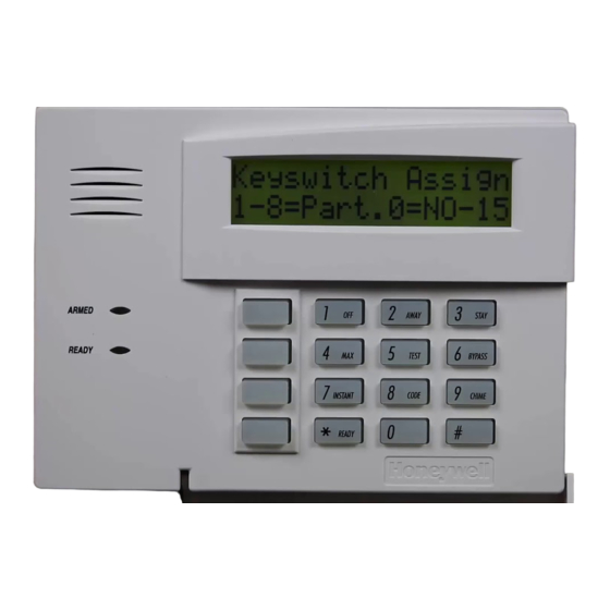
Using the Keyswitch General Your system may be equipped with a keyswitch for use when arming and disarming a partition. A red and green light on the keyswitch plate indicate the status of your system as follows: Green Light: Lights when the system is disarmed and ready to be armed (no open zones). -
Page 41: Chime Mode
Chime Mode Using the 9 Key Your system can be set to alert you to the opening of a door or window while it is disarmed by using CHIME mode. When activated, three tones will sound at the Keypad whenever a protected perimeter door or window is opened, and the Not Ready message will be displayed. -
Page 42: Viewing Alarm Company Messages
Viewing Alarm Company Messages General Information Users of the system may periodically receive messages on their display screens from their monitoring agency or installer. When a message is waiting to be viewed, the message shown below will appear. MESSAGE. PRESS 0 FOR 5 SECS. -
Page 43: Panic Keys
Panic Keys (For Manually Activating Silent and/Or Audible Alarms) Using Panic Keys Your system may have been programmed to use special key combinations to manually activate panic functions. The functions that might be programmed are Silent Emergency, Audible Emergency, Personal Emergency, and Fire. See your installer for the function(s) that may have been programmed for your system. -
Page 44: Speed Key (Macros)
Speed Key (Macros) General Information The “A”, “B”, “C”, and/or “D” keys can be used to activate a string of commands up to 32 keystrokes each. These commands are known as a macro and are stored in the system’s memory. Typical Speed Key functions include: •... -
Page 45: Executing
Speed Key (Macros) (cont’d) key is unnecessary. The system interprets the use of the # key in a Speed Key sequence as its designated function only. Executing To execute a Speed Key sequence, do the following: If a lettered key, A-B-C has been assigned as a Speed Key, press and hold down the appropriate key (about 2 seconds). -
Page 46: Access Door Control
Access Door Control General Information Your system may be set up such that a locked access door (such as in a lobby) can be unlocked momentarily or for a specific period of time, using a keypad command. Ask your installer if this has been done in our system. Executing There are several entries that can be entered at the keypad to activate this command:... -
Page 47: Using #70 Relay Menu Mode
Using #70 Relay Menu Mode General Information Your system may be set up so that certain lights or other devices can be turned on or off by using the #70 command from either a keypad or a telephone keypad (if 4286 VIP module is used). Ask your installer if this has been done in your system. -
Page 48: Using Schedules
Using Schedules Delaying the Closing Time Your system's programmed schedules may automatically arm the system at a predetermined time. In the event a user must stay on the premises later than usual, users with master or manager authority levels can manually delay the automatic arming (closing) time up to 2 hours. -
Page 49: Programming Temporary Schedules
Using Schedules (cont’d) Programming Temporary Schedules Temporary schedules only affect the partition from which it is entered. Temporary schedules can be reused at later dates simply by scrolling (by pressing #) to the DAYS? prompt (described below) and activating the appropriate days. - Page 50 Using Schedules (cont’d) This is the prompt that actually activates the DAYS ? MTWTFSS temporary schedule, and allows the temporary HIT 0-7 X X schedule to be customized to a particular week's needs. To select the days which are to be activated, enter the desired number 1-7 (Monday = 1).
-
Page 51: Programming Device Timers
Programming Device Timers General Information Device timers consist of an ON time & an OFF time, and selected days of the week in which they are active. There are up to 20 timers that can be used to control various devices, such as lights or appliances. Your installer will have programmed the appropriate devices into the system (up to 96 devices can be programmed). - Page 52 Programming Device Timers (cont’d) Enter the time you want the device turned on 00 ON TIME ? using 00:01 - 11:59 format. When the display 00:00 PM shows the desired time, press the * key to move to the AM/PM field. Press any key 0-9 to change the AM/PM indication.
-
Page 53: Randomize Output Device Times
Programming Device Timers (cont’d) Randomize Output Device Times Devices in your system may be set for a random schedule, whereby they will turn on and off at different times each day. This is useful when going on vacation and you desire the turning on and off of the lights to the give the appearance of someone being home. -
Page 54: Using #77 Instant Activation Mode
Using #77 Instant Activation Mode The #77 Instant Activation Mode is used to activate outputs, bypass zones, etc. immediately upon exiting the #77 Mode. The actions that may be activated are relay commands, arm/disarm commands, zone bypassing commands, and open/close access conditions. Relay Commands Action Code Action Specifier... - Page 55 Using #77 Instant Activation Mode (cont’d) Bypass Commands Activation times 1 (Beginning), 2 (End), 3 (During) are the only valid choices for bypass commands. If 3 (During) is selected for auto-bypassing, the system bypasses the zone(s) specified on a particular zone list at the beginning of the window and unbypasses them at the end of the window.
- Page 56 Using #77 Instant Activation Mode (cont’d) Additional Commands Action Code Action Specifier Access Point Group Enable Group # Access Point Group Disable Group # To enter the Instant Activation Mode: Enter your security code, then press the # key followed by 77. Enter the code for the desired action.
-
Page 57: Event Log Procedures
Event Log Procedures General Information The system has the ability to record various events in a history log wherein each event is recorded in one of five categories (listed below), with the time and date of its occurrence. The Event Log holds up to 1000 events, with the oldest event being replaced by the logging of any new event after the log is full. - Page 58 Event Log Procedures (continued) After the last event has been displayed, the END OF EVENT LOG message appears for a few seconds, then the system automatically displays the RECENT/COMPLETE mode select screen again (see step 2). 5. To EXIT the Event Log: Press [∗] at any time.
-
Page 59: Setting The Time And Date
Setting the Time and Date 1. Enter Installer or Master Code + # + 63. Typical display shows: TIME/DATE – THU 12:01 AM 01/01/10 The day of the week is automatically calculated based on the date entered. Time and date entries are made by simply entering the appropriate hour, minute, month, day and year. -
Page 60: Testing The System (To Be Conducted Weekly)
Testing the System (To Be Conducted Weekly) Using the 5 TEST Key The TEST key puts your system into Test mode, which allows each protection point to be checked for proper operation. 1. Disarm the system and close all protected windows, doors, etc. READY should be displayed. -
Page 61: Fire Alarm System
Fire Alarm System Your fire alarm system (if installed) is on 24 hours a day, providing continuous protection. In the event of an emergency, the smoke and heat detectors automatically send signals to your Control, triggering a loud interrupting sound from the keypad and the optional exterior sounders. -
Page 62: Trouble Conditions
Trouble Conditions Typical Trouble Displays The word CHECK or TRBL on the Keypad's display, accompanied by a rapid "beeping" at the Keypad, indicates that there is a trouble condition in the system. To silence the beeping sound for trouble conditions, press any key. •... -
Page 63: Power Failure
CALL FOR SERVICE IMMEDIATELY if AC power cannot be restored. SERVICING INFORMATION Your local Honeywell dealer is the person best qualified to service your alarm system. Arranging some kind of regular service program with him is advisable. -
Page 64: Recommendations For Proper Protection
Recommendations for Proper Protection The following recommendations for the location of fire and burglary detection devices help provide proper coverage for the protected premises. Recommendations for Smoke and Heat Detectors With regard to the number and placement of smoke/heat detectors, we subscribe to the recommendations contained in the National Fire Protection Association's (NFPA) Standard #72 noted below. -
Page 65: Recommendations For Proper Intrusion Protection
Recommendations for Proper Protection (cont’d) In addition, we recommend the following: Install a smoke detector inside every bedroom where a smoker sleeps. Install a smoke detector inside bedrooms where electrical appliances (such as portable heaters, air conditioners or humidifiers) are used. Install a smoke detector inside every bedroom where someone sleeps with the door partly or completely closed. -
Page 66: Emergency Evacuation
Emergency Evacuation Establish and regularly practice a plan of escape in the event of fire. The following steps are recommended by the National Fire Protection Association: 1. Position your detector or your interior and/or exterior sounders so that they can be heard by all occupants. 2. -
Page 67: Maintaining Your System
Maintaining Your System Taking Care of Your System The components of your security system are designed to be as free of maintenance as possible. However, there are some things you can do to make sure that your system is in reliable working condition. 1. -
Page 68: Silencing Low Battery Warning Tones At The Keypad
Maintaining Your System (cont’d) Silencing Low Battery Warning Tones at the Keypad The keypad’s warning tones can be silenced by performing an OFF sequence (code plus OFF key), but the Keypad's low battery message display will remain on as a reminder that you have a low battery condition in one or more of your sensors. -
Page 69: Quick Guide To System Functions
Quick Guide to System Functions FUNCTION PROCEDURE COMMENTS Check Zones Press [✱]. To view faulted zones when is system not ready Display All Press and hold [✱] for 5 seconds. Displays all alpha descriptors programmed by Descriptors installer. Arm System Enter code. - Page 70 Quick Guide to System Functions (cont’d) FUNCTION PROCEDURE COMMENTS Delete a User Enter master/manager code. Master & Manager level users can delete users. Press CODE [8]. A user can only be deleted by a user with higher Enter user no. to be deleted. authority level.
-
Page 71: Summary Of Audible Notification
Summary of Audible Notification (Alpha Display Keypads) SOUND CAUSE DISPLAY LOUD, FIRE ALARM FIRE is displayed; descriptor of zone in alarm is displayed. INTERRUPTED* Keypad & External LOUD, BURGLARY/AUDIBLE ALARM is displayed; descriptor of zone in alarm is also CONTINUOUS* EMERGENCY ALARM displayed. - Page 72 FEDERAL COMMUNICATIONS COMMISSION STATEMENTS The user shall not make any changes or modifications to the equipment unless authorized by the Installation Instructions or User's Manual. Unauthorized changes or modifications could void the user's authority to operate the equipment. FCC CLASS B STATEMENT This equipment has been tested to FCC requirements and has been found acceptable for use.
- Page 73 “FEDERAL COMMUNICATIONS COMMISSION (FCC) Part 68 NOTICE This equipment complies with Part 68 of the FCC rules. On the front cover of this equipment is a label that contains, among other information, the FCC registration number and ringer equivalence number (REN) for this equipment. If requested, this information must be provided to the telephone company.
- Page 74 CANADIAN DEPARTMENT OF COMMUNICATIONS (DOC) STATEMENT NOTICE AVIS The Canadian Department of Communications label L’étiquette du ministère des Communications du Canada identifies certified equipment. This certification means identifie le matériel homologué. Cette étiquette certifie que that the equipment meets certain telecommunications le matériel est conforme à...
- Page 75 WARNING! THE LIMITATIONS OF THIS ALARM SYSTEM While this system is an advanced design security system, it does not offer guaranteed protection against burglary or fire or other emergency. Any alarm system, whether commercial or residential, is subject to compromise or failure to warn for a variety of reasons.
-
Page 76: Index
Graphic/Touch-Screen Keypad.....34 Burglary Protection ........ 7 Graphic/Touch-Screen Keypad..5, 10 Bypass- Access Door ......45 Group Bypass ........31 Bypass Commands ....... 54 Honeywell Dealer........62 Bypass Zones......... 29 Instant ..........7, 22 Bypassing ..........29 INSTANT..........14 Call Service ........... 61 INSTANT Mode ........34 Carbon Monoxide Protection.... - Page 77 LO Bat ...........62 Ready ............ 27 Low Battery...........66 READY..........40 Low Battery Warning ......67 Ready Key ..........27 Macros .............7 Real-Time Clock ........69 Manager..........16 Relay Commands ........53 Master............16 Relay Menu Mode......... 46 Master Keypad ........8, 23 Replacing Batteries ......66 Maximum ..........7, 22 RF BUTTON.........
-
Page 78: Two Year Limited Warranty
TWO YEAR LIMITED WARRANTY Honeywell International Inc., acting through its Security & Communications business (“Seller”), 2 Corporate Center Drive, Melville, New York 11747 warrants its products to be free from defects in materials and workmanship under normal use and service, normal wear and tear excepted, for 24 months from the manufacture date code;... - Page 79 NOTES – 79 –...
- Page 80 2 Corporate Center Drive, Suite 100 P.O. Box 9040, Melville, NY 11747 Copyright © 2010 Honeywell International Inc. www.honeywell.com/security Ê800-06905EŠ 800-06905 6/10 Rev. C...