
Related Manuals for Bosch ICP-CC488


Summary of Contents for Bosch ICP-CC488
- Page 1 ICP-CC488 Installation Guide ICP-CC488 Control Panel...
- Page 2 Bosch. Except as specified above or where authorized by the Bosch Security Systems, Inc. reserves the right to Copyright Act 1968 (Cth), no part of this publication make changes to features and specifications of its products at any time without prior notification.
-
Page 3: Table Of Contents
Turning Telephone Monitor Mode On and Format............. 38 Off..............25 7.4.8 Command 966 – Enable/Disable the 5.1.8 Walk Test Mode ........... 26 Automatic Stepping of Locations....38 5.1.9 Event Memory Recall Mode....... 26 Bosch Security Systems, Inc. | 12/08 | F01U089457-02... - Page 4 System Status – Low Battery Report ..69 15.25 System Status – Low Battery Restore Report 13.0 Access Codes..........54 ................. 69 13.1 Installer Code..........54 15.26 System Status – Access Denied ....69 13.2 User Codes ............ 54 Bosch Security Systems, Inc. | 12/08 | F01U089457-02...
-
Page 5: Icp-Cc488 | Installation Guide | Contents En
19.3.1 Partitioning Options 1........85 24.1 Warranty Statement........100 19.3.2 Partitioning Options 2........85 24.2 Specifications ..........100 19.4 Zone Allocations ........... 85 24.3 Software Version Number ......100 19.4.1 Zone Allocations for Areas 1 and 2 ... 86 Bosch Security Systems, Inc. | 12/08 | F01U089457-02... - Page 6 Figure 22: Connections for Two CP-5 Area Table 32: Event Sequence........31 Addressable Codepads ......88 Table 33: Event Memory Playback .......32 Figure 23: ICP-CC488 Wiring Diagram ....95 Table 34: Codepad Indicators ........35 Figure 24: ICP-CC488 Component Overlay ..96 Table 35: Programming Option Bits Example..36...
- Page 7 Strobe Indications for Remote Operations..........81 Table 61: User Code Allocations......86 Table 62: Hexadecimal Values for Zone Nos..90 Table 63: Terminal Descriptions ......92 Table 64: Glossary ........... 93 Table 65: Specifications......... 100 Bosch Security Systems, Inc. | 12/08 | F01U089457-02...
-
Page 8: Introduction
Introduction EN | 8 ICP-CC488 Features 1.0 Introduction The ICP-CC488 security system uses the latest in microprocessor technology to provide you with Congratulations on selecting the ICP-CC488 Control useful features, and superior reliability and Panel for your installation. Take the time to read performance. -
Page 9: Quick Start
Enter command [9 6 0] and press [AWAY] to exit Quick Start from Installer’s Programming Mode. The following steps allow you to use the ICP-CC488 Two beeps sound and the STAY and AWAY Control Panel with factory default values. The default indicators are extinguished. -
Page 10: Zone Types
Refer to Section 3.1 Arming the System in AWAY Mode for more information. Table 5: AWAY Indicator Indicator Definition The system is armed in AWAY Mode. The system is not armed in AWAY Mode. Bosch Security Systems, Inc. | 12/08 | F01U089457-02... -
Page 11: Icp-Cp508Lw Eight Zone Lcd Codepad11
Section 3.3 to arm the system in STAY Mode 1. One short beep There is a system fault to be • every min acknowledged. Section 14.3.5 to set zones to be automatically isolated in STAY Mode 1. Bosch Security Systems, Inc. | 12/08 | F01U089457-02... -
Page 12: Icp-Cp500Pw Master Partitioned Led Codepad
ON Indicator/Zone in Alarm The ON indicator lights when the system is armed and flashes when an alarm occurs. The indicator is reset after a valid User Code is entered. Bosch Security Systems, Inc. | 12/08 | F01U089457-02... -
Page 13: Icp-Cp516 Sixteen Zone Codepads
The FAULT indicator lights when the system detects a system fault (refer to Table 7 on page 11). Refer to Section 3.12 Fault Analysis Mode on page 18 for more information on system faults. Bosch Security Systems, Inc. | 12/08 | F01U089457-02... -
Page 14: System Operations
AWAY Mode, forced arming is not permitted. If this reports as User Code number 16. is the case, you seal all zones or manually isolate them before you can arm the system. Bosch Security Systems, Inc. | 12/08 | F01U089457-02... -
Page 15: Arming The System In Stay Mode 2
The system is now disarmed. To arm the system in STAY Mode 2: 1. Press and hold [0]. 2. When two beeps sound, release the button. The STAY indicator is lit and the Exit Time starts. Bosch Security Systems, Inc. | 12/08 | F01U089457-02... -
Page 16: Disarming The System From Stay Mode
66). A codepad Panic Alarm transmits Contact ID Event Code 120 if the system reports to a base Single button disarming from STAY station receiver. Mode 2 reports as User Code16. Bosch Security Systems, Inc. | 12/08 | F01U089457-02... -
Page 17: Codepad Fire Alarm
If you make a mistake, enter the incorrect ID Event Code 571 is sent. zone number and press [STAY]. This zone is no longer selected to be isolated and the zone indicator is extinguished. Bosch Security Systems, Inc. | 12/08 | F01U089457-02... -
Page 18: Fault Analysis Mode
3 – Tamper Fail This fault occurs when a zone becomes open circuit. In Fault Analysis Mode, hold down [3] until two beeps sound to display the zone that reported the fault. Bosch Security Systems, Inc. | 12/08 | F01U089457-02... -
Page 19: System Fault Indicators
Contact your installer if this fault is displayed. AUX Power Supply fail This fault occurs when the AUX Power Supply has failed. Contact your installer when this fault occurs. Bosch Security Systems, Inc. | 12/08 | F01U089457-02... -
Page 20: Remote Radio Transmitter Operations
ICP-CC488 | Installation Guide | 4.0 Remote Radio Transmitter Operations EN | 20 Table 15: Fault Analysis Conditions Zone Indicator Fault Description Hold Down Button Zone Indicator Fault Condition System fault Low battery Date and time RF receiver jamming RF receiver tamper switch... -
Page 21: Indications From Remote Radio Transmitter Operations
ICP-CC488 | Installation Guide | 4.0 Remote Radio Transmitter Operations EN | 21 Before a hand-held radio transmitter can operate the Changing or Deleting Remote control panel, you must teach the transmitter’s radio Radio User Codes code to the control panel. Refer to Section 4.3... -
Page 22: System Functions
4. Repeat Steps 1 to 3 to add another device. This function is automatically terminated if you do not press a button within 60 sec or if you press [AWAY]. One long beep indicates that you selected an incorrect user number. Bosch Security Systems, Inc. | 12/08 | F01U089457-02... -
Page 23: Set The Number Of Days Until The First Test Report
If the repeat interval is set to 7 days, but you want phone). the first Test Report to be sent in 2 days, enter: To disable domestic dialing: [1 2 3 4 1][AWAY][2][AWAY] Enter the Installer Code and press [2][AWAY] [STAY][4][AWAY]. Bosch Security Systems, Inc. | 12/08 | F01U089457-02... -
Page 24: Change Telco Arm/Disarm Sequence
You can suspend the telco arming sequence at any call forward sequence when you disarm the system. time. To disable the telco arming sequence: Enter the Installer Code and press [3][AWAY][1] [AWAY][STAY][4][AWAY]. Bosch Security Systems, Inc. | 12/08 | F01U089457-02... -
Page 25: Setting Stay Mode 2 Zones
The corresponding zone indicator flashes. After you activate Telephone Monitor Mode, hold 3. Repeat Step 2 for each zone you want to select. down [9] until two beeps sound to initiate a Test Report. Bosch Security Systems, Inc. | 12/08 | F01U089457-02... -
Page 26: Walk Test Mode
Event Memory Recall Mode reports all alarms and each arming or disarming of the system and helps with troubleshooting system faults. The events are displayed using the codepad indicators. Bosch Security Systems, Inc. | 12/08 | F01U089457-02... -
Page 27: Master Code Functions
The default Master Code (User Code 1) is or delete a User Code. 2580. It is possible to program multiple When using a partitioned ICP-CC488 Control Panel, Master Codes. Refer to Section 13.3 User Code Priority for more information. the Master Code holder cannot add, change, or... -
Page 28: Changing And Deleting Remote Radio User Codes
5. Press [AWAY] to exit from this mode. codepad indicators light. Refer to Table 28. 3. Press [STAY] to delete the User Code. Two beeps sound and the STAY and AWAY indicators are extinguished. Bosch Security Systems, Inc. | 12/08 | F01U089457-02... -
Page 29: Change Telco Arm/Disarm Sequence
Immediate On sequence or Call Forward – No sequence, enter [STAY][1]. When you Answer sequence that automatically operates when program the # in the telco arm sequence, you arm the system in the AWAY Mode. enter [STAY][2]. Bosch Security Systems, Inc. | 12/08 | F01U089457-02... -
Page 30: Setting Stay Mode 2 Zones
[0] until two beeps sound. Refer to Section 5.4.3 or 4. Press [AWAY] to exit from this function. Section 3.5 Arming The System in STAY Mode 2 for more Two beeps sound and the STAY and AWAY indicators are extinguished. information. Bosch Security Systems, Inc. | 12/08 | F01U089457-02... -
Page 31: Setting The Date And Time
Example To set the date and time for 1st January 2009 at 10:30 PM, enter: [2 5 8 0 6][AWAY][0 1 0 1 0 9 2 2 3 0][AWAY] Bosch Security Systems, Inc. | 12/08 | F01U089457-02... -
Page 32: User Code Functions
User Code is required to disarm the system. Hold-down functions allow easy activation of specific operations. When you hold down a button for 2 sec, two beeps sound and the corresponding function operates. The hold-down functions are listed below. Bosch Security Systems, Inc. | 12/08 | F01U089457-02... -
Page 33: Horn Speaker Test
To turn Day Alarm on: Press and hold [4] until three beeps sound. On partitioned ICP-CC488 Control Panels, this hold- down function also indicates the area to which the To turn Day Alarm off: codepad belongs. -
Page 34: Send Test Report
3 sec. You can program the ICP-CC488 Control Panel You can alternatively press and hold [*] on the using any of these devices: touch-tone telephone for 3 sec to arm the system. -
Page 35: Programming With The Programming Key
After storing information in the programming Data Zone Indicators key, you can easily program other ICP-CC488 Value MAINS Control Panels with the same programming data. You can also use the programming key to back up existing information. -
Page 36: Programming Option Bits
Mode. The remote codepad displays the data stored in Location 000. 2. Connect the programming key to the PROGRAMMING KEY pins (next to the Auxiliary Module socket) at the top of the control panel printed circuit board. Bosch Security Systems, Inc. | 12/08 | F01U089457-02... -
Page 37: Command 960 - Exit From Installer's Programming Mode
This command copies data from the programming can reset the control panel from any location. key to the control panel. You can use the CC891 Programming Key only with the ICP-CC488 Control To reset the control panel to factory defaults: Panel. -
Page 38: Command 964 - Erase The Programming Key
Enter [9 6 6 #]. Command 965 simplifies the setup of the domestic Two beeps sound. dialing format to a one-step operation. Refer to Section 9.0 Domestic Dialing on page 42 for more information. Bosch Security Systems, Inc. | 12/08 | F01U089457-02... -
Page 39: Command 999 - Display The Panel Type Or Software Version Number
Codepad Indicators on page 10 for more If the Installer Code is unknown, you must restore information. the control panel to your Bosch distributor for 3. Press [#] to exit from this command and return exchange. A nominal fee applies for this service. -
Page 40: Alarm Link Software
8.0 Alarm Link Software Two beeps sound and the system returns to the disarmed state. You can program or control the ICP-CC488 Control If you are using a remote codepad, the STAY Panel remotely using an IBM or compatible personal and AWAY indicators are extinguished to computer and the CC816 Alarm Link Software. -
Page 41: Remote Connection Without Callback Verification
Direct Connection The direct connect feature gives the installer a simple Method One method to program the ICP-CC488 Control Panel Method one allows you to call the control panel from using a portable computer. Because telephone lines any remote location without the control panel calling and modems are not required, programming of the back to the computer to establish a link. -
Page 42: Domestic Dialing
Refer to Section 9.2 Setting Up and Programming event. Domestic Reporting on page 43 for more information. Bosch Security Systems, Inc. | 12/08 | F01U089457-02... -
Page 43: Setting Up And Programming Domestic Reporting
3. Enter [9 6 0] and press [AWAY] to exit from 10.1 Transmission Formats Installer’s Programming Mode. The ICP-CC488 Control Panel provides a number of Two beeps sound and the STAY and AWAY transmission formats for its dialing and indicators are extinguished. The system returns communication features. -
Page 44: Contact Id Format
Event Code. Closing Report SSSS CU Refer to Section 10.1.3 Alarm Link Options for more Test Report SSSS T information about the ICP-CC488 Point ID Codes. Program Altered SSSS P0 Duress SSSS DD 10.1.3... -
Page 45: Basic Pager Reporting Format
Receiver 1 and Receiver 2 on page 49). 4. Program the Basic Pager Format option (5) in Location 033 (refer to Section 11.4 Transmission Format for Receiver 1 and Receiver 2 on page 50). Bosch Security Systems, Inc. | 12/08 | F01U089457-02... -
Page 46: Table 43: Point Id Codes
RF Receiver Failure 15.10 Zone Specific 1 to 8 Bypass Zone Bypass 15.3 Zone Specific 1 to 8 Bypass 24-Hour Zone Bypass 15.3 Zone Specific 1 to 8 Bypass 24-Hour Fire Zone Bypass 15.3 Bosch Security Systems, Inc. | 12/08 | F01U089457-02... - Page 47 1– Alarm 1 – AC Failure 2 – Manually Isolated 8 – 0 – System Normal 3 – Auto Isolated 1 – System Fault 5 – 8 – Disarmed 9 – Armed Bosch Security Systems, Inc. | 12/08 | F01U089457-02...
-
Page 48: Basic Pager Display Information
11.0 Dialer Information 10.2 Basic Pager Display Information This section outlines the programming information required for the ICP-CC488 Control Panel when The Pager format supports only eight communicating with a base station receiver. These zones. parameters specify the telephone numbers to call,... -
Page 49: Primary Telephone Number For Receiver 1 And Receiver 2
1 – HI LO Handshake HI LO Handshake Tone is required to communicate in Contact ID Format or High Speed DTMF. Bosch Security Systems, Inc. | 12/08 | F01U089457-02... -
Page 50: Transmission Format For Receiver 1 And Receiver 2
Location 039 (Receiver 1) and Location 079 (Receiver 2). This value allows the identification of up to 15 different control panels that call the same telephone number. Bosch Security Systems, Inc. | 12/08 | F01U089457-02... -
Page 51: Telco Disarming Sequence
[12 6 1 12 0 0 0 0 0 0 0 0 0 0 0 0] system is armed, select Option 2 in Location 177 (refer to Section 12.1 Dialer Options 1 on page 52). Bosch Security Systems, Inc. | 12/08 | F01U089457-02... -
Page 52: Telephone Line Fault Options
Upload/Download using the CC816 Alarm Link disconnected. Refer to Section 3.13 Fault Descriptions Software and telephone remote arming remains on page 18 for more information. operational regardless of this setting. Bosch Security Systems, Inc. | 12/08 | F01U089457-02... -
Page 53: Dialer Options 2
65) for this option to work. 1 – Set DTMF Dialing Pulses to 1 Digit/Sec For a partitioned ICP-CC488 Control Panel, an If this option is not selected, the Australian DTMF Open/Close Report is sent only for the area in which dialing format dials at 5 digits per sec (that is, 100 ms the alarm occurred. -
Page 54: Alarm Link Options
13.2.1 User Codes This code is used to access Installer’s Programming The ICP-CC488 Control Panel can have up to Mode. The Installer Code can be up to four digits sixteen programmable User Codes (1 to 16) to long. After the control panel is powered up, the operate the system. -
Page 55: User Code Priority
User Codes, the Standard Isolating method no longer operates. Only User Codes with a priority level of 4, 6, 12, or 14 can isolate zones using the Code to Isolate method. Bosch Security Systems, Inc. | 12/08 | F01U089457-02... -
Page 56: Zone Information
An output that is programmed for Day Alarm Resetting operates when a zone programmed for Day feature allows you to install the ICP-CC488 Control Alarm is activated. The output is reset after the zone Panel at an existing site without changing the EOL is resealed. -
Page 57: Contact
10 – 6K8 1 – +12 V 5 – EOL 3K3 2 – Zone Input 6 – EOL 6K8 3 – Zone 7 – EOL 4K7 4 – N/C 8 – N/O Bosch Security Systems, Inc. | 12/08 | F01U089457-02... -
Page 58: Zone Programming
Alarm Reports for the zone. Refer to Zone Pulse Count Time Section 14.3.8 Zone Report Code on page 64 for more Zone Options 1 information. Zone Options 2 Report Code Dialer Options Bosch Security Systems, Inc. | 12/08 | F01U089457-02... - Page 59 Zone Options 1 Zone Options 2 Report Code Dialer Options Zone #12 (Default = Instant) Zone Type Zone Pulse Count Zone Pulse Count Time Zone Options 1 Zone Options 2 Report Code Dialer Options Bosch Security Systems, Inc. | 12/08 | F01U089457-02...
-
Page 60: Zone Types
Zone Restore Report is automatically speaker, bell, and strobe, whether the system is sent to the receiving party. armed or disarmed. A 24-Hour Burglary zone does not send a Restore Report until the zone is restored. Bosch Security Systems, Inc. | 12/08 | F01U089457-02... -
Page 61: Zone Pulse Count
24-Hour Zones will receive all handover activate the sirens and dialer once more. Restore pulses from other zones. 24-Hour Zones signals are sent when the system is disarmed. cannot handover pulses to other zones. Bosch Security Systems, Inc. | 12/08 | F01U089457-02... -
Page 62: Keyswitch Zone Options
Mode 1, or STAY Mode 2, the Sensor Watch Timer disarming the system in AWAY Mode is not pauses its count. The Sensor Watch Timer continues permitted from the Keyswitch Zone. its count the next time the system is disarmed. Bosch Security Systems, Inc. | 12/08 | F01U089457-02... -
Page 63: Zone Options 2
When a zone is manually isolated, a Zone Bypass Report (Contact ID Event Code 570) is sent. Refer to Section 3.11 Isolating Zones on page 17 for more information. 1 – EOL 2 – Keyswitch (Momentary/Toggle) Bosch Security Systems, Inc. | 12/08 | F01U089457-02... -
Page 64: Zone Report Code
When the dialer is online, its counter is decremented for lockout siren. only by the first zone that activated the alarm. Any other zones activated while the dialer is online do not affect the counter. Bosch Security Systems, Inc. | 12/08 | F01U089457-02... -
Page 65: System Reporting Information
1 to 15. Hour Zones that are unsealed at the end of Exit Time do not transmit a Sensor Trouble Report because the restoral for that zone is still outstanding. Bosch Security Systems, Inc. | 12/08 | F01U089457-02... -
Page 66: Zone Status - Sensor Watch Reports
Receiver 2 only when Receiver 1 fails, or no reporting. 15.5 Zone Status – Sensor Watch For a partitioned ICP-CC488 Control Panel, this location is ignored if Option 1 is selected in Location Reports 501 (refer to Section 19.3.2 Partitioning Options 2 on... -
Page 67: Rf Receiver Trouble Restore Report
Close Reports only after a previous alarm, select program the alarm as silent by selecting Option 1 in Option 1 in Location 178. Location 493 (refer to Section 18.2 System Options 2 on page 81). Bosch Security Systems, Inc. | 12/08 | F01U089457-02... -
Page 68: Codepad Fire Report
Receiver 1. You can select whether Codepad Alarm required, program Locations 418 and 419 Reports are sent to Receiver 1, Receiver 2, or both, as 0. Receiver 2 only when Receiver 1 fails, or no reporting. Bosch Security Systems, Inc. | 12/08 | F01U089457-02... -
Page 69: System Status - Low Battery Report
If Access Denied Reports are not specific signal sent to the base station receiver and is required, program Locations 424 and 425 normally used to test the dialing and reporting as 0. functions of the control panel. Bosch Security Systems, Inc. | 12/08 | F01U089457-02... -
Page 70: Test Reporting Dialer Options
Time Base Multiplier Output 2 (Default – Fire Alarm With Verification) 16.0 Programmable Outputs Event Code Event Code The ICP-CC488 Control Panel has four fully- Polarity programmable outputs on the main printed circuit Time Base board and one programmable output that operates the codepad buzzer. -
Page 71: Redirecting Outputs To The Codepad Buzzer
The output is reset when the system is armed. If the Entry Timer 2, or Entry Guard Timer for STAY system is partitioned, this output operates when both Mode. The output is reset when the Entry Time areas are disarmed. expires. Bosch Security Systems, Inc. | 12/08 | F01U089457-02... - Page 72 Horn Speaker Monitor Fail to operate for Day Alarm. If the Enable Monitoring of Horn Speaker option (2) If the ICP-CC488 Control Panel is partitioned, in Location 492 is selected (refer to Section 18.1 System pressing [AWAY] on a CP5 Area Addressable...
-
Page 73: Table 55: Horn Speaker Beeps
This output operates when a 24-Hour Fire Zone is System disarmed activated and is reset when the system is armed or System armed in AWAY Mode disarmed. System armed in STAY Mode 1 Bosch Security Systems, Inc. | 12/08 | F01U089457-02... - Page 74 If you select Option 8 in Location 492 (refer to during which the output operates. Section 18.1 System Options 1 on page 80), this output does not operate and arms the system in STAY Mode 1 only. Bosch Security Systems, Inc. | 12/08 | F01U089457-02...
- Page 75 These outputs Area 2 Codepad Data Terminal are reset when a valid User Code is entered. This output type is used to connect the data terminal of the Area 2 codepad. Bosch Security Systems, Inc. | 12/08 | F01U089457-02...
-
Page 76: Output Polarity
The output parameters do not apply to this polarity. switches back to 0 V when the event is restored. Time parameters vary the Off time of the pulse. Bosch Security Systems, Inc. | 12/08 | F01U089457-02... -
Page 77: Output Timing
This section covers the features that involve timing, 200 ms such as Entry and Exit Times, Sensor Watch Time, 1 sec Siren Run Time, and System Date and Time. 1 min 1 hour Bosch Security Systems, Inc. | 12/08 | F01U089457-02... -
Page 78: Programming Entry/Exit Timers
Sensor Watch. Exit Time is near. The remote codepad always sounds one short beep at the end of Exit Time when arming in STAY Mode 1 or STAY Mode 2. Bosch Security Systems, Inc. | 12/08 | F01U089457-02... -
Page 79: Codepad Lockout Time
These locations specify the time of day the system automatically disarms itself. Set this time in 24-hour format (for example, program 10:30 PM as 2230). User Code 16 is reported when this feature is used. Bosch Security Systems, Inc. | 12/08 | F01U089457-02... -
Page 80: Kiss-Off Wait Time
Minute of the day (tens digit) Minute of the day (units digit) 18.1 System Options 1 The ICP-CC488 Control Panel has a real-time 24- Location hour clock you must set during installation. Set this Bosch Security Systems, Inc. smart lockout allowed... -
Page 81: System Options 2
2 min regardless Fire Alarm, program Locations 407 and 408 as 0 of whether this option is selected. (refer to Section 15.17 Codepad Fire Report on page 66). Bosch Security Systems, Inc. | 12/08 | F01U089457-02... -
Page 82: System Options 4
4 – Auto Arm in STAY Mode 1 returns to being armed or disarmed as it was before the power failed. Select this option if automatic arming in STAY Mode 1 is preferred to automatic arming in AWAY Mode. Bosch Security Systems, Inc. | 12/08 | F01U089457-02... -
Page 83: Consumer Options 2
Selecting this option allows you to connect a memory from the remote codepad. momentary keyswitch to the TS2 terminals D and GND to remotely arm and disarm the system in AWAY Mode. Bosch Security Systems, Inc. | 12/08 | F01U089457-02... -
Page 84: Partitioning
Normally, arming and disarming the system turns the The display and operations of a CP5 Area entire system on or off. When the ICP-CC488 Addressable (CP500A) codepad in a partitioned Control Panel is partitioned, you can arm or disarm system are exactly the same as the CP5 Eight Zone an individual area without affecting the other area. -
Page 85: Partitioning Options 1
If this option is selected, the DATA terminal on the Refer to Sections 5.2.1 and 5.3.1 for more information. ICP-CC488 Control Panel is configured to send only If the user arms both areas at the same time and status information that is relevant to Area 1. This... -
Page 86: Zone Allocations For Areas 1 And 2
Allocated to Area 1 and Area 2 19.6 Setting Up and Programming Codepads for Partitioning Only the CP5 Area Addressable (CP500A) and CP5 Master Partitioned (CP500P) codepads can be used with a partitioned ICP-CC488 Control Panel. Bosch Security Systems, Inc. | 12/08 | F01U089457-02... -
Page 87: Setting Up The Master Partitioned Codepad As The Main Codepad
6,1 Area 2 Codepad Data (refer to page 75). Set DIP switch 2 on the back of the Area 2 codepad to the ON position (refer to Figure 20 on page 87). Bosch Security Systems, Inc. | 12/08 | F01U089457-02... -
Page 88: Rf Information
4 – Unseal Zone that Fails Supervision If a wireless zone device fails to send a signal within the RF Supervision Time programmed in Location 393 (refer to Section 15.8) the codepad zone indicator lights as unsealed. Bosch Security Systems, Inc. | 12/08 | F01U089457-02... -
Page 89: Rf Device Mapping Option
Map RF Device 8 to Zone Mapping Option on page 89. (1 to 16) 0-15 Mapping RF device to zone 1-16 The programming for zone numbers 1 through 8 is in hexadecimal code (00 through 15). Bosch Security Systems, Inc. | 12/08 | F01U089457-02... -
Page 90: Rf Device Signal Strength (Devices 1 To 8) (Read Only)
8 (highest). 21.0 Optional Equipment Bosch Security Systems, Inc. manufactures a number of accessories that can be used in conjunction with the ICP-CC488 Control Panel. These optional pieces of equipment enhance certain features to make the system extremely flexible. 21.1... -
Page 91: Ss914 Edmsat Satellite Siren
This software package is designed to program the inside the casing. ICP-CC488 Control Panel by either the direct link or The plug pack incorporates a three-wire flying lead remote connect methods. This software can access all... -
Page 92: Terminals And Descriptions
EOL resistor. The function of the zones and their response times are configured using the system programming options. If split EOL is programmed, 24-Hour Zones or Keyswitch Zones connected in parallel to Zones 1 and 2 act as Zones 5 and 6. Bosch Security Systems, Inc. | 12/08 | F01U089457-02... -
Page 93: Glossary Of Terms
A device used to arm and disarm a security system or to cause a panic alarm. remote control lockout dialer A dialer that activates only once per zone per arming cycle. Bosch Security Systems, Inc. | 12/08 | F01U089457-02... - Page 94 A monitored input used to activate an alarm. A zone might be set up to activate an alarm only when the system is armed or to operate whether the system is armed or disarmed. Bosch Security Systems, Inc. | 12/08 | F01U089457-02...
-
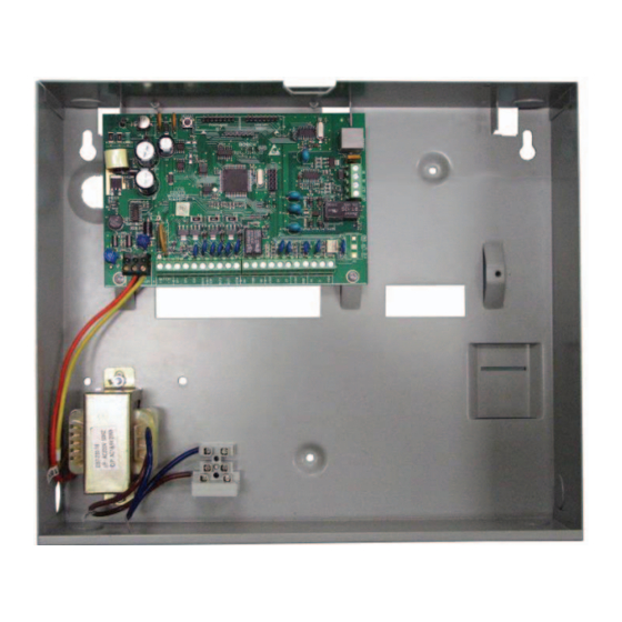
Page 95: Diagrams
22 – Battery 5 – Zone 2 14 – Smoke detector 23 – 18 VAC 1.3 A plug pack 6 – Zone 6 (TF008) 24 – Link between +12 V and Comm Bosch Security Systems, Inc. | 12/08 | F01U089457-02... - Page 96 IN – Telecom line (street) 9 – Default switch 3 – Receiver interface connection 10 – Programming key 4 – Zone termination strip 11 – Auxiliary Module: direct link cable 5 – Output termination strip Bosch Security Systems, Inc. | 12/08 | F01U089457-02...
-
Page 97: Australia
2 (black): telecom line (street) 5 – 605 plug 3 and 4: not connected 6 – Internal phones 5 (yellow): internal phone line 7 – Green wire 6 (red): telecom line (street) Bosch Security Systems, Inc. | 12/08 | F01U089457-02... - Page 98 4 – 4P4C plug (top view) (red): telecom line (street) 5 – RJ12 plug (top view) 9 – Yellow wire 6 – Telecom line 10 – Green wire 7 – Internal phones Bosch Security Systems, Inc. | 12/08 | F01U089457-02...
-
Page 99: Appendices
The ICP-CC488 Control Panel allows you to save between the would-be burglar and the control panel. time and money by providing Test Reports only Anyone with a little knowledge of alarm systems can when the system is armed. -
Page 100: Specifications
Standby Current 65 mA 115 mA Current Draw In If you use the ICP-CC488 Control Panel, you can cut Alarm Condition the calls to 624,000 per year (at a value of $156,000 105 mA Current Draw In assuming local calls), a saving of $65,000. -
Page 101: A-Tick
24.5 A-Tick Handshake Tone for Receiver 2 Location Refer to page 49 The ICP-CC488 Control Panel is designed to comply with A-Tick. HI-LO handshake (contact ID) 1400 Hz (Ademco TX @ 1900 Hz) 2300 Hz (low speed Sescoa) No handshake Pager Bosch Security Systems, Inc. - Page 102 0 0 0 0 0 0 0 0 0 0 0 0 0 0 0 0 Ring Count Refer to page 51 Location Default Panel will not answer 1 to 13 Number of rings until panel answers Answering machine bypass 2 Answering machine bypass 1 Bosch Security Systems, Inc. | 12/08 | F01U089457-02...
- Page 103 Open/Close Reports Arm/disarm and Master Code functions Arm/disarm, Master Code functions, and Open/Close Reports Arm/disarm, Master Code functions, and code to isolate Arm/disarm, Master Code functions, code to isolate, and Open/Close Reports Bosch Security Systems, Inc. | 12/08 | F01U089457-02...
- Page 104 Sensor watch The last two locations contain reporting information: Zone Options 2 Report Code Dialer Options Option Description Isolated in STAY Mode 1 Zone isolation allowed Forced arming allowed Enable Zone Restore Report Bosch Security Systems, Inc. | 12/08 | F01U089457-02...
- Page 105 Refer to page 66 Receiver 2 only when Receiver 1 fails Default Codepad Duress Report Location 389 Sensor Watch Report Location 390 Sensor Watch Restore Report Location Refer to page 67 Default Bosch Security Systems, Inc. | 12/08 | F01U089457-02...
- Page 106 Receiver 2 Location 470 Increments of 1 sec (0 to 15 sec) Receiver 1 and 2 Location 471 Increments of 16 sec (0 to 240 sec) Receiver 2 only when Receiver 1 fails Bosch Security Systems, Inc. | 12/08 | F01U089457-02...
- Page 107 Single button disarming allowed (STAY Modes 1 Location 489 Minute of the day – units digit and 2) Kiss-Off Wait Time Alarm memory reset on disarm Location Refer to page 80 Default Location 490 Increments of 500 ms Bosch Security Systems, Inc. | 12/08 | F01U089457-02...
- Page 108 Area 2 – Zone 6 indicator Location 516 Area 2 – Zone 7 indicator Location 517 Area 2 – Zone 8 indicator Not mapped for this LED This LED used, a zone is mapped to it Bosch Security Systems, Inc. | 12/08 | F01U089457-02...
- Page 109 Map RF Device 8 to Zone (1 to 16) Location 837 0-15 Mapping RF device to zone 1-16 Country Code Location 838 to 839 Refer to page 89 Location Default Country Code (tens digit) Country Code (units digit) Bosch Security Systems, Inc. | 12/08 | F01U089457-02...
-
Page 110: Country Codes
Venezuela Burkina-faso Laos Tanzania Hong Kong, Vietnam Burma Lesotho Togo Hungary Burundi Liberia Tuvalu India Armenia Cambodia Libya Uganda Indonesia Belarus Cameroon Madagascar United Arab Emirates Ireland Georgia Cape Verde Malawi Uruguay Bosch Security Systems, Inc. | 12/08 | F01U089457-02... -
Page 111: Zealand
Mexico East Timor Namibia Netherlands Algeria Ecuador Nauru New Zealand Bahrain El Salvador Nepal Nigeria French Equatorial Gui Nicaragua Polynesia Norway Iceland Eritrea Niger Peru Israel Ethiopia Palau Philippines Lebanon Fiji Panama Bosch Security Systems, Inc. | 12/08 | F01U089457-02... - Page 112 ICP-CC488 | Installation Guide | Index EN | 112 Notes Bosch Security Systems, Inc. | 12/08 | F01U089457-02...
- Page 113 Answering Machine Bypass ........51 Codepad Fire To Be Silent...........81 Call Back Telephone Number......51 Codepad Indicators Dialing Format............50 AWAY..............10 Primary Telephone Number For Receiver 1 ..49 AWAY Indicator............ 11 Bosch Security Systems, Inc. | 12/08 | F01U089457-02...
- Page 114 Option Bits ........36, 41, 52, 56, 61, 63 Optional Equipment Installer Code ..............54 2 Channel Radio Interface........90 Installer Code Function 8 Zone LED Codepad ........... 91 Change Telco Arm/Disarm Sequence ..24, 29 Bosch Security Systems, Inc. | 12/08 | F01U089457-02...
-
Page 115: Disarming The System From Stay Mode
First To Open/Last To Close Reporting..... 85 Fire Alarm Latching ..........73 Main Codepad To Display Data Only For Area 185 Fire Alarm Resetting..........73 Partitioning Options 2 Fire Alarm Verification ......... 74 Bosch Security Systems, Inc. | 12/08 | F01U089457-02... - Page 116 STAY Mode 2 Isolating Allowed............ 63 Arming............... 15, 32 Options 1 ..............58 Setting Zones ............ 25, 30 Pulse Count ............. 61 Strobe Test..............33 Pulse Count Handover .......... 61 System Disarmed ............12 System Operations Bosch Security Systems, Inc. | 12/08 | F01U089457-02...
- Page 117 Chime Zone ............61 Lockout Siren & Dialer ......... 61 Delay-1 Zone............60 Sensor Watch............62 Delay-2 Zone............60 Zone Options 2 Handover Zone............60 Isolate In STAY Mode 1........63 Instant Zone ............60 Bosch Security Systems, Inc. | 12/08 | F01U089457-02...
- Page 118 Bosch Security Systems, Inc. 130 Perinton Parkway Fairport, NY 14450-9199 USA www.boschsecurity.com © 2008 Bosch Security Systems, Inc. F01U089457-02...