Table of Contents
Quick Links
See also:
Manual
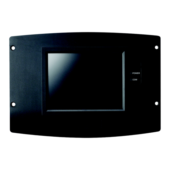
S7999B, S7999C SOLA
Local Operator Interface
APPLICATION
The S7999B and S7999C are microprocessor-based touch-
screen Operator Interface (OI) displays that provide an
operator interface for monitoring and configuring parameters
in the Sola Hydronic Control and Sola Steam Control system.
The S7999B can be used to monitor an individual boiler but is
primarily used for multiple boiler applications in a lead/lag
arrangement. COM 2 port is available for Building Automation
applications. The S7999B display is flush mounted into a
panel cutout (8-1/8 in. W x 5-7/8 in. H). Wiring connections to
the S7999B are through a removable 9-pin wiring header.
The S7999C display is used for individual boiler monitoring.
The S7999C is mounted:
• onto a panel using the wallplate provided.
• from the front into a panel cutout (7.6 in. W X 5.4 in. H)
using 4 #6-32 screws and nuts (provided).
Preface .............................................................................
Specifications ...................................................................
Installation Instructions (S7999B OI Display) ...................
Wiring (S7999B OI Display) .............................................
Starting the S7999B OI Display ........................................
Configuration .................................................................... 20
Details .............................................................................. 38
R7910A or R7911 Diagnostics ......................................... 44
S7999B or S7999C Display Setup and Diagnostics ......... 47
Advanced Setup ............................................................... 48
Table 61 Configurable Parameters. .................................. 53
Table 62 Other Tables. ..................................................... 61
• From behind into a panel cutout (5.45 in. W X 4.3 in. H)
using 4 #6-32 screws, nuts and 4 standoffs (provided).
Wiring connections to the S7999C are made via a 4-pin
connector on the back of the display.
NOTE: If display S7999B is used to monitor a lead/lag sys-
tem, display S7999C can NOT be used.
FEATURES
• Individual boiler status, configuration, history, and
diagnostics.
• Allows configuration and monitoring of the Sola
Controls (R7910A Hydronic Controls or R7911 Steam
Control) burner control sequence, flame signal,
diagnostics, historical files, and faults.
• S7999B OI Display only:
- Allows switching view between multiple boilers
- Allows viewing Lead-Lag Master
- Ethernet port for downloading software upgrades
(when required)
- Real-time data trending analysis and transferring
saved trend data to Excel spreadsheet.
- Audible Alarm
- COM 2 Modbus port for Building Automation System
applications.
- LED indicators:
• Power
• Network
• COM 2
• COM 1
- Models available:
• S7999B1026 has Blue Border
• S7999B1067 has Black Border
• S7999C OI Display only:
Contents
2
3
4
4
7
PRODUCT DATA
65-0303-05
Table of Contents

Related Manuals for Honeywell S7999B


Summary of Contents for Honeywell S7999B
-
Page 1: Table Of Contents
Sola Hydronic Control and Sola Steam Control system. saved trend data to Excel spreadsheet. — Audible Alarm The S7999B can be used to monitor an individual boiler but is — COM 2 Modbus port for Building Automation System primarily used for multiple boiler applications in a lead/lag applications. -
Page 2: Preface
If you have additional questions, need further information, or would like to comment on our products or services, please write or phone: 1. Your local Honeywell Automation and Control Products Sales Office (check white pages of your phone directory). 2. Honeywell Customer Care... -
Page 3: Specifications
(137) 1-33/64 (39) PANEL HOLE CUTOUT SIZE 7-19/32 (193) WIDE X 5-13/32 (137) HIGH FOR S7999B DISPLAY 7.6 WIDE X 5.4 HIGH.. M29867A Fig. 1. OI Display dimensions (S7999C shown) in in. (mm). NOTE: This equipment has been tested and found to comply with the limits for a Class A digital device, pursuant to part 15 of the FCC Rules. -
Page 4: Installation Instructions (S7999B Oi Display)
The OI Display can be mounted on the door panel of an electrical enclosure. The S7999B OI Display must be appropriately wired for both power and communications. An external 12V power supply 1. Select the location on the door panel to mount the dis- (provided) with an appropriate power rating is connected to play;... - Page 5 ECOM V ADJ SOLA CONTROL WIRING KEY LINE VOLTAGE DO NOT CONNECT THE S7999B TO TERMINALS 1 2 3. THIS WILL RENDER THE DISPLAY INOPERABLE. LOW VOLTAGE DISPLAY CAN ALSO BE CONNECTED TO MB2; A, B, C. DATA M32004 Fig. 3. S7999B wiring diagram.
- Page 6 Fig. 4. S7999B wiring diagram for lead lag. BUILDING AUTOMATION Ensure all S7999B devices have unique Modbus addresses as defined in Fig. 5. SYSTEM (BAS) CONFIGURATION Connect the BAS Modbus wiring to COM2 of the S7999B as shown in Fig. 5. 65-0303—05...
-
Page 7: Starting The S7999B Oi Display
Modbus message from Sola before sending a port and two for Modbus™ ports. The ethernet port should only new Modbus message. be used if instructed by Honeywell that an update is necessary. Modbus Com Port 2 is not active on this device. QUICK SETUP (S7999B OI 1. - Page 8 47 (see also Table 61 on page 53). It also contains the setup configuration for BAS applications, under the Advanced Fig. 6. S7999B Home page (Boiler 1 in normal operation). Setup button. Pressing the SOLA icon opens that control’s status page. Go to “Configure Button”...
-
Page 9: Installation Instructions
Analog M13965 Fig. 8. S7999B display page flow. INSTALLATION INSTRUCTIONS 2-3/4 (70) (S7999C OI DISPLAY) (13) NOTE: For S7999B OI Display installation instructions, see 1-21/32 page 4. (42) The S7999C display is used for individual boiler monitoring. 3-13/64 (81) The S7999C is mounted: •... - Page 10 S7999B, S7999C SOLA LOCAL OPERATOR INTERFACE 4. Drill 3/16 in. holes for mounting the display. 5. Secure the OI Display to the panel using the four #6-32 screws and nuts, as shown in Fig. 10. (Standoffs are pro- vided for mounting the OI Display from the back of the door.)
- Page 11 S7999B, S7999C SOLA LOCAL OPERATOR INTERFACE S7999C MID-LEVEL DISPLAY – V-INFINITY FSC-S5-12U WIRING KEY LINE VOLTAGE ECOM S7999C LOW VOLTAGE MID-LEVEL DISPLAY DATA SOLA LL MASTER AND SLAVE 1 – DO NOT CONNECT THE S7999C TO TERMINALS 1 2 3. THIS WILL RENDER THE DISPLAY INOPERABLE.
-
Page 12: Page Navigation
Function (see Fig. 8 for S7999B or Fig. 13 for S7999C). The configuration settings. page descriptions are provided below so that you can... -
Page 13: Configuration Password
S7999C OI Display setup and diagnostic functions (See page 47 for options). (The same function as the 1234 Setup on the S7999B home page.) The configuration page allows the user to view and set parameters that define how the connected R7910A functions in the hydronic heating system or the R7911 steam heating system. - Page 14 Pressing the OK or Cancel buttons NOTE: For the S7999B System OI display, each boiler in a returns the user to the page displayed prior to the keyboard multi-boiler configuration has its own set of installer page.
-
Page 15: Change Parameter Settings
S7999B, S7999C SOLA LOCAL OPERATOR INTERFACE Change Parameter Settings Like operating parameters, safety parameters can be viewed without the need to enter a password. Change parameter settings by selecting the parameter on the page. A dialog box displays for the parameter with controls Safety parameter blocks that have been changed require allowing the user to change the value (see Fig. - Page 16 Safety lockouts are indicated on each configuration page as an alarm bell symbol. At the home (for S7999C) or status page (for S7999B), the History button turns red. If the S7999B is displaying the system status icons, the control in alarm will turn red.
- Page 17 S7999B, S7999C SOLA LOCAL OPERATOR INTERFACE of history to view. The user can also silence an audible alarm The date and time that each fault occurred is displayed in the generated by the control during a lockout or alert by alarm lockout history.
- Page 18 S7999B, S7999C SOLA LOCAL OPERATOR INTERFACE Fig. 27. Control expanded lockout detail. Fig. 29. Hydronic operation page shown. Fig. 28. Control expanded alert detail. Fig. 30. Programmable annunciation. Operation Button The operation button displays the SOLA Control running operation, including setpoint and firing rate values. From this page the user can change setpoints, manually control the boiler’s firing rate, manually turn pumps on, view annunciation...
- Page 19 S7999B, S7999C SOLA LOCAL OPERATOR INTERFACE Diagnostics Button System Configuration (S7999B OI DisplayOnly) The Diagnostics button displays analog and digital I/O status of the SOLA Control. A snapshot of the diagnostic status is The OI Display has some functions related to general displayed and updated once per second as it changes in the configuration for the control in the end user installation.
-
Page 20: Configuration
Lead Lag Master Configuration Most of this configuration is performed by either the contractor/ installer or at Honeywell. Each functional group is displayed on the Configuration menu page. Fig. 36. System synchronization. Parameters in functional groups that are not applicable for the installation can be ignored. - Page 21 Lead Lag passwords most likely have been changed by Honeywell. Setpoint source Local Factory Data gives Honeywell an option to display a brand S2 (J8-6) 4-20mA name other than Sola on this configuration page. Additional Setpoint Setpoint for normal Central Heat information displayed on this page is listed in Table 7.
- Page 22 S7999B, S7999C SOLA LOCAL OPERATOR INTERFACE Table 8. Central Heat Hydronic Table 9. Steam Configuration Parameters Configuration Parameters. (Continued) Parameter Comment Parameter Comment Steam pressure on Differential from setpoint when boiler Modulation Rate Local hysteresis is turned on. Sensor Adjustable 0 to 15 or 0 to 150 (sensor...
- Page 23 S7999B, S7999C SOLA LOCAL OPERATOR INTERFACE Domestic Hot Water (DHW) Table 11. Domestic Hot Water (DHW) Configuration Parameters. (Continued) Configuration Parameters Parameter Comment (R7910A Hydronic Control Only) Hysteresis step ___hour ___min ___sec Table 11 displays Domestic Hot Water (DHW) configuration time parameters.
- Page 24 S7999B, S7999C SOLA LOCAL OPERATOR INTERFACE Table 13. DHW Plate Heat Exchanger Configuration Parameters. (Continued) Table 14. Warm Weather Setpoint Configuration Parameters. Parameter Comment Parameter Comment Plate preheat -40 °F to 266 °F (-40 °C to 130 °C) setpoint Enable...
-
Page 25: Modulation Configuration
S7999B, S7999C SOLA LOCAL OPERATOR INTERFACE Modulation Configuration Steam Modulation Configuration Parameters Parameters Table 15 displays R7910A Hydronic Control Modulation Table 16 displays R7911 Steam Modulation Configuration configuration parameters. parameters. Fig. 43. Modulation configuration. Fig. 44. Steam modulation configuration. Table 15. R7910A Hydronic Control Modulation Configura- Table 16. - Page 26 S7999B, S7999C SOLA LOCAL OPERATOR INTERFACE Pump Configuration Parameters NOTE: The R7911 Steam Control does not have pumps, but the outputs are available to operate air dampers or Table 17 displays Pump configuration parameters. Use the left accessories. CH Pump, Boiler Pump and System and right arrows to switch between Central Heat, Boiler, DHW, Pump are used for these output options.
- Page 27 S7999B, S7999C SOLA LOCAL OPERATOR INTERFACE Statistics Configuration Parameters High Limit Configuration Parameters (R7910A Hydronic Control Only) Table 15 displays Statistics configuration parameters. Table 19 displays outlet high limit configuration parameters. Fig. 46. Statistics configuration. Fig. 47. High Limits configuration.
- Page 28 S7999B, S7999C SOLA LOCAL OPERATOR INTERFACE Stack Limit Configuration Parameters Delta T Limit Configuration Parameters Table 20 displays stack limit configuration parameters. (R7910A Hydronic Control Only) Table 21 displays other limit parameters. Use the left and right arrows to switch between Inlet to Outlet Flow and Exchanger to Outlet Flow.
- Page 29 S7999B, S7999C SOLA LOCAL OPERATOR INTERFACE T-Rise Limit Configuration Anti-Condensation Configuration Parameters Parameters (R7910A Hydronic Control Only) Table 22 displays T-Rise limit parameters. Table 24 displays anti-condensation parameters. Use the left and right arrows to switch between Central Heat, Domestic Hot Table 22.
- Page 30 S7999B, S7999C SOLA LOCAL OPERATOR INTERFACE Frost Protection Parameters Annunciation Configuration (R7910A Hydronic Control Only) Parameters Table 25 displays frost protection parameters. Table 26 displays annunciation configuration parameters. Fig. 51. Frost Protection configuration. Fig. 52. Annunciation configuration example. Table 25. Frost Protection Configuration Parameters.
- Page 31 S7999B, S7999C SOLA LOCAL OPERATOR INTERFACE Fig. 53. Burner Control Interlocks control. Fig. 54. Burner Control Timings and Rates configuration. Table 27. Burner Control Table 28. Burner Control Timings and Rates Configura- Interlocks Configuration. tion. Parameter Comment Parameter Comment PII enable...
- Page 32 S7999B, S7999C SOLA LOCAL OPERATOR INTERFACE Table 30. Burner Control Flame Failure Configuration. (Continued) Table 29. Burner Control Ignition Configuration. Ignite failure retries 1, 3, or 5 Parameter Comment MFEP flame failure Recycle Pilot test hold response Lockout Run flame failure...
- Page 33 S7999B, S7999C SOLA LOCAL OPERATOR INTERFACE After successful login, the user presses the Begin button to After the first safety parameter group has been confirmed by start safety parameter verification. See Fig. 59. the user (by pressing the Yes button), the next safety parameter group waits for verification as shown in Fig.
- Page 34 S7999B, S7999C SOLA LOCAL OPERATOR INTERFACE If for some reason the user does not press the Reset button on the control within 30 seconds, the configuration is cancelled, as shown in Fig. 65. Fig. 63. Reset R7910A or R7911. When the user has pressed the Reset button on the control, completing verification procedure, a Verification Complete Fig.
- Page 35 S7999B, S7999C SOLA LOCAL OPERATOR INTERFACE Individual R7910A or R7911 Table 32. R7911 System Configuration Parameters. (Continued) Configuration Parameters Parameter Comment Table 31 and Table 32 displays system configuration parameters for individual controls. Anti short cycle time ___hour ___min ___sec...
- Page 36 S7999B, S7999C SOLA LOCAL OPERATOR INTERFACE Lead Lag Slave Configuration Use the left and right arrows to switch between Modulation, CH, DHW, Frost Protection, Warm Weather Shutdown, Parameters (Hydronic Control Only) Algorithms, Rate Allocation, Add stage and Drop stage parameters.
- Page 37 S7999B, S7999C SOLA LOCAL OPERATOR INTERFACE Table 37. Lead Lag Master Configuration Table 41. Lead Lag Master Configuration Advanced Settings: Central Heat Parameters. Advanced Settings: Algorithms Parameters. Parameter Comment Parameter Comment Demand switch Stat Lead selection Sequence order Remote Stat...
-
Page 38: Details
S7999B, S7999C SOLA LOCAL OPERATOR INTERFACE DETAILS R7910A or R7911 Status Data in Tables 45–Table 56 are displayed on the R7910A Hydronic or R7911 Steam status pages. A complete list of Details of the hydronic or steam system is accomplished Status tables can be found in Table 60 on page 53. - Page 39 S7999B, S7999C SOLA LOCAL OPERATOR INTERFACE Table 46. DHW Hydronic Status. (Continued) Data Comment DHW high limit Temp setting between -40 °F to 266 °F (-40 °C to 130 °C) DHW high limit Temp setting between -40 °F to 266 °F setpoint (-40 °C to 130 °C)
- Page 40 S7999B, S7999C SOLA LOCAL OPERATOR INTERFACE Table 47. Burner Control Status. (Continued) Data Comment Firing rate % or RPM. Adjustable when firing rate control set to Manual. Firing rate control Auto or Manual Flame signal Flame signal strength Hold code...
- Page 41 S7999B, S7999C SOLA LOCAL OPERATOR INTERFACE Hydronic Demand and Modulation Status Table 49 displays the status page data for R7910A. Table 48. Hydronic Demand and Modulation Status. Data Comment Demand source CH, DHW, Lead Lag, or Frost Protection (parameter that has current...
- Page 42 S7999B, S7999C SOLA LOCAL OPERATOR INTERFACE Table 50. Control Fan Status. Data Comment Fan speed % or RPM (current fan speed) Maximum fan speed Setpoint of maximum fan speed (% or RPM) Minimum fan speed Setpoint of minimum fan speed (% or RPM) The bar graph displayed for this status is the fan speed.
- Page 43 S7999B, S7999C SOLA LOCAL OPERATOR INTERFACE Statistics Status Stack Limit Status Table 53 displays the statistics status page data for the Table 54 shows the status page data for the control Stack Limit. R7910A or R7911. Though the Steam control will not have a pump, the output can be used to run some other auxiliary Table 54.
-
Page 44: R7910A Or R7911 Diagnostics
S7999B, S7999C SOLA LOCAL OPERATOR INTERFACE Fig. 89. Lead Lag Slave Status menu. Fig. 90. Lead Lag Master Status menu. Lead Lag Master Status - Hydronic R7910A OR R7911 Only DIAGNOSTICS Table 56 shows the status page data for Lead Lag Master. - Page 45 S7999B, S7999C SOLA LOCAL OPERATOR INTERFACE Table 57. Control Digital I/O Data. Data Comment Pump C On/Off Blower/HSI On/Off Pilot valve On/Off Main valve On/Off Load Control Input On/Off STAT On/Off Pre-ignition interlock On/Off Interlock On/Off External ignition On/Off Alarm...
- Page 46 S7999B, S7999C SOLA LOCAL OPERATOR INTERFACE INSTALLER CHECKOUT Diagnostics Tests Pressing the Diagnostics Test button launches the diagnostic tests. The first test displayed on the right side of the screen is the last selected test shown, as seen in Fig. 97.
-
Page 47: S7999B Or S7999C Display Setup And Diagnostics
S7999B or S7999C OI Displays. Setup The Setup button on the Home page (for S7999B OI Display) or Display Setup Button on the Configuration Screen for the S7999C OI Display is selected to go to these pages. The Setup screen (see Fig. -
Page 48: Advanced Setup
S7999B has been assigned by the DHCP server in the local network to use for others to access the S7999B. This address is necessary for the remote user to identify the S7999B in an FTP (File Transfer Protocol) application for transferring trend analysis information. - Page 49 Trend analysis of R7910 or R7911 status data can be viewed on the S7999B. A graph displays a historical view of R7910 or R7911 status data over varying time periods. A 2-dimensional graph with status data values shown on the Y axis over time specified on the X axis is displayed.
- Page 50 A snapshot of the trend analysis graph can be taken and saved to the S7999B. The user is asked to confirm the save before it occurs. NOTE: While this snapshot is saved, trend data sampling for all R7910s or R7911s is temporarily halted.
- Page 51 Trend Analysis Snapshot The trend analysis snapshot file is stored in Comma Separated Value (CSV) format in the S7999B so it can be imported into a spreadsheet program such as Microsoft Excel. The trend analysis snapshot file can be viewed in graph form on the S7999B.
- Page 52 S7999B, S7999C SOLA LOCAL OPERATOR INTERFACE The Display clock is set by selecting the Date and Time button on the Advanced Setup page. A screen similar to the following figure (Fig. 114) displays. NOTE: It’s important that the time be set in the Display so correct timestamps are given to the R7910A or R7911 lockouts.
-
Page 53: Table 61 Configurable Parameters
Fig. 118. COM1 tab. Fig. 120. Processor Reset. S7999B Only When the Display is reset, the display will reboot and automatically seek out the Modbus™ device connected to it. When the search is COM2 is a Modbus gateway for Building Automation System (BAS) complete, the display will return to the home page. - Page 54 S7999B, S7999C SOLA LOCAL OPERATOR INTERFACE Table 61. Configurable Parameters. (Continued) Table 61. Configurable Parameters. (Continued) Table Page Table Page Parameter Comment Parameter Comment CH enable Disable or Enable Central Steam Disable/enable steam feature Heating Loop enable CH demand Sensor for Central Heat...
- Page 55 Table 61. Configurable Parameters. (Continued) Table 61. Configurable Parameters. (Continued) Table Page Table Page Parameter Comment Parameter Comment DHW enable Disable or Enable Domestic Hot Tap detect -0 °F to 180 °F (-17 °C to 82 °C) 13 Water Loop degrees Sensor for Central Heat Tap detect on...
- Page 56 S7999B, S7999C SOLA LOCAL OPERATOR INTERFACE Table 61. Configurable Parameters. (Continued) Table 61. Configurable Parameters. (Continued) Table Page Table Page Parameter Comment Parameter Comment CH maximum RPM or % Auxiliary Auto modulation pump control rate Auxiliary CH pump is ON...
- Page 57 S7999B, S7999C SOLA LOCAL OPERATOR INTERFACE Table 61. Configurable Parameters. (Continued) Table 61. Configurable Parameters. (Continued) Table Page Table Page Parameter Comment Parameter Comment DHW high Enabled Heat Enabled limit Disabled exchanger Disabled high limit DHW high Suspend DHW enable limit Recycle &...
- Page 58 S7999B, S7999C SOLA LOCAL OPERATOR INTERFACE Table 61. Configurable Parameters. (Continued) Table 61. Configurable Parameters. (Continued) Table Page Table Page Parameter Comment Parameter Comment CH frost Enabled PII enable Enabled protection Disabled Disabled enable LCI enable Enabled DHW frost Enabled...
- Page 59 S7999B, S7999C SOLA LOCAL OPERATOR INTERFACE Table 61. Configurable Parameters. (Continued) Table 61. Configurable Parameters. (Continued) Table Page Table Page Parameter Comment Parameter Comment Pilot test hold On Flame sensor Flame rod type UV power tube UV power tube with spark...
- Page 60 S7999B, S7999C SOLA LOCAL OPERATOR INTERFACE Table 61. Configurable Parameters. (Continued) Table 61. Configurable Parameters. (Continued) Table Page Table Page Parameter Comment Parameter Comment Absolute Modulation Lead outlet sensor maximum fan backup Slave outlet sensor average speed sensor Disabled Absolute 0 °F to 234 °F...
-
Page 61: Table 62 Other Tables
S7999B, S7999C SOLA LOCAL OPERATOR INTERFACE Table 61. Configurable Parameters. (Continued) Table 61. Configurable Parameters. (Continued) Table Page Table Page Parameter Comment Parameter Comment Lead Sequence order Method Error threshold selection Measured run time Firing rate threshold method Disabled Lag selection... - Page 62 S7999B, S7999C SOLA LOCAL OPERATOR INTERFACE 65-0303—05...
- Page 63 M28852 Fig. 121. S7999C front-mount template. 65-0303—05...
- Page 64 S7999B, S7999C SOLA LOCAL OPERATOR INTERFACE 65-0303—05...
- Page 65 M28851 Fig. 122. S7999C rear-mount template. 65-0303—05...
- Page 66 S7999B, S7999C SOLA LOCAL OPERATOR INTERFACE 65-0303—05...
- Page 67 S7999B, S7999C SOLA LOCAL OPERATOR INTERFACE 65-0303—05...
- Page 68 S7999B, S7999C SOLA LOCAL OPERATOR INTERFACE Automation and Control Solutions Honeywell International Inc. 1985 Douglas Drive North Golden Valley, MN 55422 Honeywell Limited-Honeywell Limitée 35 Dynamic Drive ® U.S. Registered Trademark Toronto, Ontario M1V 4Z9 © 2010 Honeywell International Inc.