
Related Manuals for Honeywell KI 209


Summary of Contents for Honeywell KI 209
- Page 1 RELEASED FOR THE EXCLUSIVE USE BY: AIRCRAFT ELECTRONICS ASSOCIATION INSTALLATION MANUAL KI 208, KI 209 NAVIGATION INDICATORS MANUAL NUMBER 006-00140-0004 Revision 4, August 2002...
- Page 2 ©1988, 1996, 2002 HONEYWELL INTERNATIONAL INC. REPRODUCTION OF THIS PUBLICATION OR ANY PORTION THEREOF BY ANY MEANS WITHOUT THE EXPRESS WRITTEN PERMISSION OF HONEYWELL IS PROHIBITED. FOR FURTHER INFORMATION CONTACT THE MANAGER, TECHNICAL PUBLICATIONS, HONEYWELL, ONE TECHNOLOGY CENTER, 23500 WEST 105TH...
- Page 3 RELEASED FOR THE EXCLUSIVE USE BY: AIRCRAFT ELECTRONICS ASSOCIATION BENDIX/KING KI 208, KI 209 REVISION HISTORY INSTALLATION MANUAL BENDIX/KING KI 208, KI 209 Navigation Indicators PART NUMBER DATE DESCRIPTION --------------------------------------------------------------------------------------------------------------------- 006-00140-0004 Aug/2002 Replaces P/N 006-00140-0003. 006-00140-0003 Oct/1996 Replaces P/N 006-00140-0002.
- Page 4 RELEASED FOR THE EXCLUSIVE USE BY: AIRCRAFT ELECTRONICS ASSOCIATION BENDIX/KING KI 208, KI 209 THIS PAGE RESERVED Rev 4, Aug 2002 IM 006-00140-0004 RH-2...
-
Page 5: Table Of Contents
List..................2-6 Crimping Tool ..................2-7 KI 208, KI 209 Connector Assembly ............2-8 KI 208, KI 209 Outline and Mounting ..(Dwg 155-05235-0000) ... 2-9 KI 208, KI 209 Typical Interconnect ............. 2-11 KI 208 Non-TSO’d System Interconnect. (Dwg 155-01223-0000) ..2-13 KI 209 System Interconnect.... - Page 6 BENDIX/KING KI 208, KI 209 SECTION III OPERATION Paragraph Page Equipment Operation ................3-1 Indicator Control Functions KI 208, KI 209 ..........3-2 LIST OF ILLUSTRATIONS Figure Page KI 208 Control Functions ................. 3-3 KI 209 Control Functions ................. 3-4...
-
Page 7: Introduction
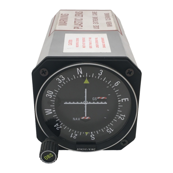
The KI 208 converts this information to DC signals which drive the LEFT-RIGHT needle and the TO-OFF-FROM flag of the visual indicator. The KI 209 ILS Indicator performs the same functions as the KI 208. In addition, it contains an UP-DOWN glideslope needle with an OFF warning flag. -
Page 8: Units And Accessories Supplied
RELEASED FOR THE EXCLUSIVE USE BY: AIRCRAFT ELECTRONICS ASSOCIATION BENDIX/KING KI 208, KI 209 TABLE 1-1 Technical Characteristics KI 208, KI 209 SPECIFICATION CHARACTERISTIC VOR/LOC: Input Impedance: 50 k ohms, nominal. Nominal Composite Input Level: LOC: 0.33 ±10% Vrms. VOR: 0.50 ±10% Vrms ARINC phased. -
Page 9: Accessories Required, But Not
LICENSE REQUIREMENTS None. REQUIREMENTS FOR TSO’D VOR/ILS/GLIDESLOPE SYSTEM Units used in conjunction with the KI 208, KI 209 must meet the specifications listed below to comprise a completely TSO’d navigation system. 1.7.1 Navigation Receiver Requirements For Use with KI 208, KI 209. - Page 10 DC current of 260 uA minimum into a 1000 ohm load. 1.7.3 Fully TSO’D Systems The following navigation systems will meet all TSO system requirements when used in conjunction with the KI 208, KI 209: KX 155 KX 155A KX 165A...
-
Page 11: General
The KI 208, KI 209 installation will conform to standards designated by the customer, installing agency and existing conditions as to unit location and type of installation. -
Page 12: Post Installation Checkout
RELEASED FOR THE EXCLUSIVE USE BY: AIRCRAFT ELECTRONICS ASSOCIATION BENDIX/KING KI 208, KI 209 just potentiometer. This is for final calibration of the omni system after install- ing in aircraft. The range of the error potentiometer is approximately ±25°. It should be noted that this potentiometer does not affect localizer centering. -
Page 13: Ils Deflection
RELEASED FOR THE EXCLUSIVE USE BY: AIRCRAFT ELECTRONICS ASSOCIATION BENDIX/KING KI 208, KI 209 2.4.1.7 Remove VOR RF signal and verify that NAV warning flag appears. 2.4.1.8 Set ramp generator to ILS mode. Set NAV receiver to ILS frequency. Check the levels in Table 2-1 for ILS deflection and Table 2-2 for Glideslope deflec- tion within ±1/2 dot. - Page 14 RELEASED FOR THE EXCLUSIVE USE BY: AIRCRAFT ELECTRONICS ASSOCIATION BENDIX/KING KI 208, KI 209 2.4.2.2 Flight test the ILS operation by flying a simulated ILS approach. Check local- izer LEFT-RIGHT deflection and, if applicable, glideslope deflection. Check the localizer accuracy in relation to the ILS runway.
-
Page 15: Ki 208 Pinout
RELEASED FOR THE EXCLUSIVE USE BY: AIRCRAFT ELECTRONICS ASSOCIATION BENDIX/KING KI 208, KI 209 Figure 2-1 KI 208 Pinout List Rev 4, Aug 2002 IM 006-00140-0004 Page 2-5... -
Page 16: Ki 209 Pinout
RELEASED FOR THE EXCLUSIVE USE BY: AIRCRAFT ELECTRONICS ASSOCIATION BENDIX/KING KI 208, KI 209 Figure 2-2 KI 209 Pinout List Rev 4, Aug 2002 IM 006-00140-0004 Page 2-6... - Page 17 RELEASED FOR THE EXCLUSIVE USE BY: AIRCRAFT ELECTRONICS ASSOCIATION BENDIX/KING KI 208, KI 209 Figure 2-3 Crimping Tool Rev 4, Aug 2002 IM 006-00140-0004 Page 2-7...
- Page 18 RELEASED FOR THE EXCLUSIVE USE BY: AIRCRAFT ELECTRONICS ASSOCIATION BENDIX/KING KI 208, KI 209 Figure 2-4 KI 208, KI 209 Connector Assembly Rev 4, Aug 2002 IM 006-00140-0004 Page 2-8...
- Page 19 BENDIX/KING KI 208, KI 209 FIGURE 2-5 KI 208, KI 209 Outline and Mounting Drawing (Dwg No 155-05235-0000, Rev 4) Rev 4, Aug 2002 IM 006-00140-0004 Page 2-9...
- Page 20 BENDIX/KING KI 208, KI 209 FIGURE 2-6 KI 208, KI 209 Typical Interconnect Rev 4, Aug 2002 IM 006-00140-0004 Page 2-11...
- Page 21 BENDIX/KING KI 208, KI 209 FIGURE 2-7 KI 208 Non-TSO’d Silver Crown System Interconnect (Dwg No 155-01223-0000, Rev 4) Rev 4, Aug 2002 IM 006-00140-0004 Page 2-13...
-
Page 22: Ki 209 System
BENDIX/KING KI 208, KI 209 FIGURE 2-8 KI 209 System Interconnect (Dwg No 155-01241-0000, Rev 4) Rev 4, Aug 2002 IM 006-00140-0004 Page 2-15... - Page 23 KI 208, KI 209 SECTION III OPERATION EQUIPMENT OPERATION All controls required to operate the KI 208, KI 209 are located on the unit’s front panel and on the front panel of the related NAV/COMM transceivers. 3.1.1 VOR OPERATION (KI 208, KI 209) Select the desired VOR station frequency with the NAV frequency controls.
- Page 24 If the needle deflects downward, the aircraft is above the glide path and must descend to remain on the glide path. When the needle is centered the aircraft is on the glide path. INDICATOR CONTROL FUNCTIONS KI 208, KI 209 Figure 3-1 displays the control functions of the KI 208.
- Page 25 RELEASED FOR THE EXCLUSIVE USE BY: AIRCRAFT ELECTRONICS ASSOCIATION BENDIX/KING KI 208, KI 209 Figure 3-1 KI 208 Control Functions Rev 4, Aug 2002 IM 006-00140-0004 Page 3-3...
- Page 26 RELEASED FOR THE EXCLUSIVE USE BY: AIRCRAFT ELECTRONICS ASSOCIATION BENDIX/KING KI 208, KI 209 Figure 3-2 KI 209 Control Functions Rev 4, Aug 2002 IM 006-00140-0004 Page 3-4...