HP 1800 24G - ProCurve Switch Installation And Getting Started Manual
Installation guide
Hide thumbs
Also See for 1800 24G - ProCurve Switch:
- Specifications (5 pages) ,
- Management and configuration manual (57 pages)
Table of Contents
Table of Contents

Related Manuals for HP 1800 24G - ProCurve Switch


Summary of Contents for HP 1800 24G - ProCurve Switch
- Page 1 Installation and Getting Started Guide ProCurve Switch 1800-24G www.procurve.com...
- Page 3 ProCurve Switch 1800-24G Installation and Getting Started Guide...
- Page 4 Hewlett-Packard assumes no responsibility for the use or reliability of its software on equipment that is not furnished by Hewlett-Packard. Warranty See the Customer Support/Warranty booklet included with the product. A copy of the specific warranty terms applicable to your Hewlett-Packard products and replacement parts can be obtained from your HP Sales and Service Office or authorized dealer.
-
Page 5: Table Of Contents
Contents 1 Switch Overview Switch Hardware Features ........1 LEDs . - Page 6 HP Customer Support Services ........3 Before Calling Support .
-
Page 7: Switch Overview
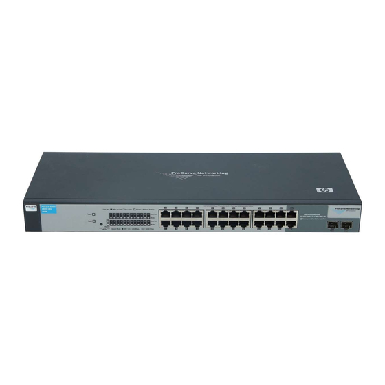
Switch Overview Switch Hardware Features The ProCurve Switch 1800-24G (J9028B) is a multiport switch that can be used to build high-performance switched workgroup networks. This switch is a store-and-forward device that offers low latency for high-speed networking. ProCurve Switch 1800-24G Port Link/Act and Power LED Mode LEDs... -
Page 8: Leds
Switch Overview Switch Hardware Features LEDs The front panel of the switch provides status LEDs for system monitoring. The following table details the functions of the various indicators. System LED State Meaning Power The switch is receiving power. (green) The switch is NOT receiving power. LED Mode Indicates the port Mode LEDs are lit for ports that are in full-duplex mode. -
Page 9: Switch Features
Switch Overview Switch Hardware Features Mode LEDs LED Mode Select button and indicator LEDs ■ When the FDx (full duplex) indicator LED is on, the port Mode LEDs turn on for those ports that are operating at full duplex. When the Speed indicator LED is on, the port Mode LEDs turn on for ports ■... - Page 10 Switch Overview Switch Hardware Features ■ easy management of the switch through several available interfaces: • Web browser interface — an easy to use built-in graphical interface that can be accessed from common Web browsers. • ProCurve Manager (PCM) — allows network administrators to discover and map the ProCurve Switch 1800 within their network and launch the ProCurve Switch 1800's built-in graphical interface from within PCM to configure the switch.
-
Page 11: Installing The Switch
Installing the Switch The ProCurve Switch 1800-24G device is easy to install. It comes with an accessory kit that includes the brackets for mounting the switch in a standard 19-inch telco rack, in an equipment cabinet, and with rubber feet that can be attached so the switch can be securely located on a horizontal surface. -
Page 12: Installation Procedure
Installing the Switch Installation Procedure Installation Procedure Prepare the installation site (page 2-3). Please see below for some installation precautions. Verify the switch passes self test (page 2-4). Mount the switch (page 2-6). Connect power to the switch (page 2-10). Connect the network cables (page 2-10). -
Page 13: Prepare The Installation Site
Installing the Switch Installation Procedure Installation Precautions (Continued) ■ Ensure the power source circuits are properly grounded, then use the C a u t i o n s power cord supplied with the switch to connect it to the power source. If your installation requires a different power cord than the one supplied ■... -
Page 14: Verify The Switch Passes Self Test
Installing the Switch Installation Procedure Installation Space Requirements Switch Clearance Requirements Orientation Front At least 7.6 cm (3 inches) of space for the twisted-pair and fiber-optic cabling. Back At least 3.8 cm (1 1/2 inches) of space for the power cord and switch cooling. Sides At least 7.6 cm (3 inches) for cooling, except if the switch is installed in an open EIA/TIA rack. - Page 15 Installing the Switch Installation Procedure Check the LEDs on the switch as described below. Port Link/Act and Mode LED Power LED When the switch is powered on, it performs its diagnostic self test. The self test takes approximately 15 seconds to complete. Self Test LED Behavior: During the self test: •...
-
Page 16: Mount The Switch
Installing the Switch Installation Procedure 3. Mount the Switch The switch can be mounted in these ways: in a rack or cabinet ■ on a horizontal surface ■ ■ on a wall Rack or Cabinet Mounting The switch is designed to be mounted in any EIA-standard 19-inch telco rack or communication equipment cabinet. - Page 17 Installing the Switch Installation Procedure N o t e The mounting brackets have multiple mounting holes and can be rotated allowing for a wide variety of mounting options. These include mounting the switch so its front face is flush with the face of the rack, or mounting it in a more balanced position as shown in the illustration.
- Page 18 Installing the Switch Installation Procedure Place the switch in the rack and lower it so the notches in the bottom of the bracket slide onto the screws, then tighten these screws. Lower switch with mounting brackets onto the partially installed screw Install the other number 12-24 screw into the upper hole in each bracket.
- Page 19 Installing the Switch Installation Procedure Wall Mounting You can mount the switch on a wall with either the front or rear panel facing W A R N I N G For safe operation, please read the “Installation Precautions” on page 2-2 page 2-3, before mounting the switch.
-
Page 20: Connect The Switch To A Power Source
Installing the Switch Installation Procedure Horizontal Surface Mounting Place the switch on a table or other horizontal surface. The switch comes with rubber feet in the accessory kit that can be used to help keep the switch from sliding on the surface. Attach the rubber feet to the four corners on the bottom of the switch within the embossed angled lines. -
Page 21: Installing Or Removing Mini-Gbics
Installing the Switch Installation Procedure 6. Installing or Removing mini-GBICs You can install or remove a mini-GBIC from a mini-GBIC slot without having to power off the switch. Use only ProCurve mini-GBICs. N o t e ■ The mini-GBIC slots are shared with 10/100/1000Base-T RJ-45 ports 23 and 24. - Page 22 Installing the Switch Installation Procedure Removing the mini-GBICs: N o t e You should disconnect the network cable from the mini-GBIC before removing it from the switch. Depending on when you purchased your ProCurve mini-GBIC, it may have either of three different release mechanisms: a plastic tab on the bottom of the mini-GBIC, a plastic collar around the mini-GBIC, or a wire bail.
-
Page 23: Configuring The Switch
Configuring the Switch Initial Configuration The ProCurve Switch 1800-24G can be managed through a Web-browser interface that you can access from any PC or workstation in the connected network. For initial configuration, you may want to assign an IP address to the switch that is compatible with your existing network. -
Page 24: Changing The Pc's Ip Address
Configuring the Switch Changing the PC’s IP Address From the menu, click SYSTEM, then IP Address. On the IP Address page, enter the IP address, Subnet Mask and Gateway IP Address for the switch, then click on the APPLY button. No other configuration changes are required at this stage, but it is recommended that you configure an administrator password before logging out. -
Page 25: Troubleshooting
Troubleshooting This section describes how to troubleshoot the switch. For more information, see the chapter “Troubleshooting” in the ProCurve Series 1800 Switch Management and Configuration Guide, available on the ProCurve Networking Web site, http://www.procurve.com This chapter describes the following: ■ basic troubleshooting tips (page 4-1) -
Page 26: Diagnosing With The Leds
Troubleshooting Diagnosing with the LEDs Diagnosing with the LEDs LED patterns on the switch may indicate a problem condition. Check in the table below for the LED pattern you see on your switch. Refer to the corresponding diagnostic tip on the next few pages. LED Pattern Indicating Problems Port LED Diagnostic Tips... -
Page 27: Forgotten The Ip Address Or Password
Troubleshooting Forgotten the IP Address or Password Forgotten the IP Address or Password If you have forgotten the switch’s IP address or administration password you can return the switch to its factory default state by doing the following: Remove the power cord from the back of the switch. Remove all cables from the front-panel ports. -
Page 28: Before Calling Support
Troubleshooting HP Customer Support Services Before Calling Support Before calling your networking dealer or HP Support, to make the support process most efficient, you first should have retrieved the following information: Information Item Information Location • product identification, including mini- the front of the switch, and on labels on the GBICs mini-GBICs... -
Page 29: Switch Specifications
Switch Specifications Physical Width: 44 cm (17.42 in) Depth: 17 cm (6.74 in) Height: 4.4 cm (1.73 in) Weight: 1.97 kg (4.32 lbs) Electrical The switch automatically adjusts to any voltage between 100-240 volts and either 50 or 60 Hz. AC voltage: 100-127 volts, 200-240 volts Maximum current:... -
Page 30: Connectors
Switch Specifications Connectors ■ The 10/100/1000 Mbps RJ-45 twisted-pair ports are compatible with the following standards: • IEEE 802.3ab 1000Base-T • IEEE 802.3u 100Base-TX • IEEE 802.3 10Base-T ■ The 1000 Mbps LC fiber-optic ports on the Gigabit-SX and Gigabit-LX mini- GBIC transceivers are compatible with the IEEE 802.3z Gigabit-SX and Gigabit-LX standards. -
Page 31: Safety And Emc Regulatory Statements
Safety and EMC Regulatory Statements Safety Information Documentation reference symbol. If the product is marked with this symbol, refer to the product documentation to get more information about the product. WARNING A WARNING in the manual denotes a hazard that can cause injury or death. - Page 32 Safety and EMC Regulatory Statements Safety Information Informations concernant la sécurité Symbole de référence à la documentation. Si le produit est marqué de ce symbole, reportez-vous à la documentation du produit afin d'obtenir des informations plus détaillées. WARNING Dans la documentation, un WARNING indique un danger susceptible d'entraîner des dommages corporels ou la mort.
-
Page 33: Hinweise Zur Sicherheit
Safety and EMC Regulatory Statements Safety Information Hinweise zur Sicherheit Symbol für Dokumentationsverweis. Wenn das Produkt mit diesem Symbol markiert ist, schlagen Sie bitte in der Produktdokumentation nach, um mehr Informationen über das Produkt zu erhalten. WARNING Eine WARNING in der Dokumentation symbolisiert eine Gefahr, die Verletzungen oder sogar Todesfälle verursachen kann. -
Page 34: Considerazioni Sulla Sicurezza
Safety and EMC Regulatory Statements Safety Information Considerazioni sulla sicurezza Simbolo di riferimento alla documentazione. Se il prodotto è contras- segnato da questo simbolo, fare riferimento alla documentazione sul prodotto per ulteriori informazioni su di esso. WARNING La dicitura WARNING denota un pericolo che può causare lesioni o morte. -
Page 35: Consideraciones Sobre Seguridad
Safety and EMC Regulatory Statements Safety Information Consideraciones sobre seguridad Símbolo de referencia a la documentación. Si el producto va marcado con este símbolo, consultar la documentación del producto a fin de obtener mayor información sobre el producto. WARNING Una WARNING en la documentación señala un riesgo que podría resultar en lesiones o la muerte. - Page 36 Safety and EMC Regulatory Statements Safety Information Safety Information (Japan)
- Page 37 Safety and EMC Regulatory Statements Safety Information Safety Information (China)
-
Page 38: Emc Regulatory Statements
Safety and EMC Regulatory Statements EMC Regulatory Statements EMC Regulatory Statements U.S.A. FCC Class A This equipment has been tested and found to comply with the limits for a Class A digital device, pursuant to part 15 of the FCC Rules. These limits are designed to provide reasonable protection against harmful interference when the equipment is operated in a commercial environment. - Page 39 Safety and EMC Regulatory Statements EMC Regulatory Statements Japan VCCI Class A Korea Taiwan...
-
Page 40: European Community
EMC Directive 89/336/EEC and carries the CE marking accordingly. Tested with Hewlett-Packard Co. products only. Roseville, 07-March-2007 Michael E. Avery, Regulatory Engineering Manager European Contact: Your local Hewlett-Packard Sales and Service Office or Hewlett-Packard GmbH, Department TRE, Herrenberger Strasse 140, D-71034 Böblingen (FAX:+49-7031-14-3143). B-10... - Page 41 Safety and EMC Regulatory Statements EMC Regulatory Statements Regulatory Information (China) ProCurve Networking by HP B-11...
-
Page 43: C Recycle Statements
Recycle Statements Waste Electrical and Electronic Equipment (WEEE) Statements Disposal of Waste Equipment by Users in Private Household in the European Union This symbol on the product or on its packaging indicates that this product must not be disposed of with your other household waste. - Page 44 Recycle Statements Waste Electrical and Electronic Equipment (WEEE) Statements Laitteiden hävittäminen kotitalouksissa Euroopan unionin alueella Jos tuotteessa tai sen pakkauksessa on tämä merkki, tuotetta ei saa hävittää kotitalousjätteiden mukana. Tällöin hävitettävä laite on toimitettava sähkölaitteiden ja elektronisten laitteiden kierrätyspisteeseen. Hävitettävien laitteiden erillinen käsittely ja kierrätys auttavat säästämään luonnonvaroja ja varmistamaan, että...
- Page 45 Recycle Statements Waste Electrical and Electronic Equipment (WEEE) Statements Smaltimento delle apparecchiature da parte di privati nel territorio dell'Unione Europea Questo simbolo presente sul prodotto o sulla sua confezione indica che il prodotto non può essere smaltito insieme ai rifiuti domestici. È responsabilità dell'utente smaltire le apparecchiature consegnan- dole presso un punto di raccolta designato al riciclo e allo smaltimento di apparecchiature elettriche ed elettroniche.
- Page 46 Recycle Statements Waste Electrical and Electronic Equipment (WEEE) Statements Descarte de Lixo Elétrico na Comunidade Européia Este símbolo encontrado no produto ou na embalagem indica que o produto não deve ser descartado no lixo doméstico comum. É responsabilidade do cliente descartar o material usado (lixo elétrico), encaminhando-o para um ponto de coleta para reciclagem.
- Page 47 Index basic troubleshooting tips … 4-1 LEDs blinking LEDs behavior during self test … 2-5 error indications … 4-2–4-3 descriptions of … 1-2 error indications … 4-2–4-3 LED Mode View select indicators … 1-2 Power … 1-2 cabinet behavior during self test … 2-5 mounting the switch in …...
- Page 48 precautions mounting the switch … 2-2 power requirements … 2-2 preparing the installation site … 2-3 rack mounting precautions … 2-2 mounting the switch in … 2-6, 2-9 recycle statements … C-1 regulatory statements … B-8 safety and regulatory statements … B-1 safety specifications …...
- Page 52 Technical information in this document is subject to change without notice. © Copyright 2006, 2007 Hewlett-Packard Development Company, L.P. Reproduction, adaptation, or translation without prior written permission is prohibited except as allowed under the copyright laws. Printed in China April 2007...