HP ProCurve 1700-8 Installation And Getting Started Manual
Hide thumbs
Also See for ProCurve 1700-8:
- Management and configuration manual (57 pages) ,
- Datasheet (5 pages)
Table of Contents
Table of Contents

Related Manuals for HP ProCurve 1700-8


Summary of Contents for HP ProCurve 1700-8
- Page 1 Installation and Getting Started Guide ProCurve Switch 1700-8 www.procurve.com...
- Page 3 ProCurve Switch 1700-8 Installation and Getting Started Guide...
- Page 4 © Copyright 2006, 2007 Hewlett-Packard Disclaimer Development Company L.P. HEWLETT-PACKARD COMPANY MAKES NO WARRANTY OF ANY KIND WITH The information contained herein is REGARD TO THIS MATERIAL, subject to change without notice. INCLUDING, BUT NOT LIMITED TO, This document contains proprietary...
-
Page 5: Table Of Contents
Contents 1 Switch Overview Switch Hardware Features ......1-1 LEDs ..........1-2 Switch Features . - Page 6 Hardware Diagnostic Tests ......4-4 Testing the Switch by Resetting It ....4-4 HP Customer Support Services .
-
Page 7: Switch Overview
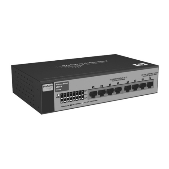
Switch Overview Switch Hardware Features The ProCurve Switch 1700-8 (J9079A) is a multiport switch that can be used to build high-performance switched workgroup networks. This switch is a store-and-forward device that offers low latency for high-speed networking. 10/100Base-TX RJ-45 ports Power 10/100/1000 Base-T (all ports have the HP Auto-MDIX feature) -
Page 8: Leds
Switch Overview Switch Hardware Features LEDs The front panel of the switch provides status LEDs for system monitoring. The following table details the functions of the various indicators. System LED State Meaning Power The switch is receiving power. (green) The switch is NOT receiving power. Port LED State Meaning... -
Page 9: Switch Features
Switch Overview Switch Hardware Features Switch Features The features of the ProCurve Switch 1700-8 include: 7 auto-sensing 10/100Base-TX ports and 1 auto-sensing 10/100/ ■ 1000Base-T RJ-45 port. plug-and-play networking—all ports are enabled—just connect ■ the network cables to active network devices and your switched network is operational. - Page 10 Switch Overview Switch Hardware Features support for up to 4 trunks so you to assign physical links to one ■ logical link (trunk) that functions as a single, higher-speed link providing dramatically increased bandwidth. support for many advanced features to enhance network ■...
-
Page 11: Installing The Switch
Installing the Switch The ProCurve Switch 1700-8 is easy to install. It comes with rubber feet that can be attached so the switch can be securely located on a horizontal surface. This chapter shows how to install the switch. Included Parts The following components ship with a ProCurve Switch 1700-8: ProCurve Switch 1700-8 Installation and Getting Started Guide ■... - Page 12 Installing the Switch Included Parts Japan Power Cord Warning A country specific power cord is required for use with this adapter. The power cord part numbers are as follows: Power Cord Part Number Region 8120-6317 South Africa 8120-6313 United States/Canada/Philippines 8120-6314 Europe/Denmark/Switzerland/Israel/Vietnam/Indonesia 8121-0870...
-
Page 13: Installation Procedures
Installing the Switch Installation Procedures Installation Procedures Summary Follow these easy steps to install your switch. The rest of this chapter provides details on these steps. Prepare the installation site. Make sure of the following: • the network cabling is the correct type and length. See page 2-5. -
Page 14: Installation Precautions
Installing the Switch Installation Procedures Installation Precautions: Follow these precautions when installing your switch. Cautions Make sure you use the power adapter supplied with the ■ switch to connect it to an AC power source. When installing the switch, since the unit does not have ■... -
Page 15: Prepare The Installation Site
Installing the Switch Installation Procedures 1. Prepare the Installation Site Cabling Infrastructure - To ensure proper operation when ■ installing the switch into a network, make sure that the current cables are suitable for 10Base-T, 100Base-TX, or 1000Base-T operation. Be sure to follow the guidelines below to ensure proper operation when installing the switch into a network: •... -
Page 16: Verify The Switch Passes Self Test
Installing the Switch Installation Procedures 2. Verify the Switch Passes Self Test Before mounting the switch in its network location, you should first check that it is working properly by plugging it into a power source and verifying that it passes its self test. Connect the adapter’s power cord to the power connector on the back of the switch, and then plug the AC power adapter into a nearby properly grounded electrical outlet. - Page 17 Installing the Switch Installation Procedures Check the LEDs on the switch. The LED behavior is described below. Port LEDs Power LED When the switch is powered on, it performs its diagnostic self test. The self test takes approximately 8 seconds to complete. Self Test LED Behavior: During the self test: •...
-
Page 18: Mount The Switch
Installing the Switch Installation Procedures 3. Mount the Switch After you have verified that the switch passes its self test, you are ready to mount the switch in a stable location. The switch can be mounted on a horizontal surface. Horizontal Surface Mounting Place the switch on a table or other horizontal surface. -
Page 19: Connect The Network Cables
Installing the Switch Installation Procedures 5. Connect the Network Cables Using the RJ-45 Connectors (10/100/1000Base-T ports) To connect: Push the RJ-45 plug into the RJ-45 jack until the tab on the plug clicks into place. When power is on for the switch and for the connected device, the Link/Act LED for the port should light to... -
Page 21: Configuring The Switch
Configuring the Switch Initial Configuration The ProCurve Switch 1700-8 can be managed through a Web-browser interface that you can access from any PC or workstation in the connected network. For initial configuration, you may want to assign an IP address to the switch that is compatible with your existing network. -
Page 22: Changing Pc's Ip Address
Configuring the Switch Changing PC’s IP Address address to 192.168.2.x (where "x" can be any number from 1 to 255, except 10). If you are unfamiliar with this process, see “Changing PC’s IP Address” on page 3-2. Open your Web browser and enter the address http://192.168.2.10. If your PC is properly configured, you will see the login page of your switch. -
Page 23: Where To Go From Here
Configuring the Switch Where to Go From Here In General tab, under Components checked are used by this connection, click to select Internet Protocol (TCP/IP), and then click Properties to open Internet Protocol (TCP/IP) Properties dialog box. In Internet Protocol (TCP/IP) Properties dialog box, click to select Use the following IP address. -
Page 25: Troubleshooting
Troubleshooting This section describes how to troubleshoot the switch. For more information, see the chapter “Troubleshooting” in the ProCurve Series 1700 Switch Management and Configuration Guide, which is available on the ProCurve Networking Web site, http://www.procurve.com This chapter describes the following: basic troubleshooting tips (page 4-1) ■... -
Page 26: Diagnosing With The Leds
Troubleshooting Diagnosing With the LEDs Problem Resolution Switch fails Power On Troubleshoot using the LEDs. See “Diagnosing With Self Test (POST) the LEDs” on page 4-2 Link light does not light Look for loose or obviously faulty connections. If when a cable is they appear to be OK, make sure the connections connected. -
Page 27: Diagnostic Tips
Troubleshooting Diagnosing With the LEDs Diagnostic Tips: Problem Solution Number ➊ The switch’s 1. Verify the AC power adapter is plugged into an active power source and to the switch. Make power adapter sure these connections are snug. is not plugged into an active 2. -
Page 28: Forgotten The Ip Address Or Password
Troubleshooting Forgotten the IP Address or Password Forgotten the IP Address or Password If you have forgotten the switch’s IP address or administration password you can return the switch to its factory default state by doing the following: Remove the power adapter from the back of the switch. Remove all cables from the front-panel ports. -
Page 29: Hp Customer Support Services
Troubleshooting HP Customer Support Services HP Customer Support Services If you are still having trouble with your switch, ProCurve Networking offers support 24 hours a day, seven days a week through the use of a number of automated electronic services. See the Customer Support/Warranty booklet that came with your switch for information on how to use these services to get technical support. -
Page 31: Physical
Specifications Physical Width: 19.6 cm (7.7 in) Depth: 11.6 cm (4.5 in) Height: 4.4 cm (1.73 in) Weight : 0.54 kg (1.19 lbs) Electrical DC voltage: 12-13 volts Maximum current: 1.0-0.8 A Environmental Operating Non-Operating 0 °C to 40 °C (32 °F to 104 °F) -40 °C to 70 °C (-40 °F to 158 °F) Temperature: 10 % to 90 % at 40 °C (104 °F) 10 % to 90 % at 65 °C (149 °F) Relative humidity:... -
Page 32: Connectors
Specifications Connectors The 10/100/1000 Mbps RJ-45 twisted-pair ports are compatible ■ with the following standards: • IEEE 802.3ab 1000Base-T • IEEE 802.3u 100Base-TX • IEEE 802.3 10Base-T Safety The switch complies with these safety standards: EN60950-1 / IEC 60950-1 ■ CSA 22.2 No. -
Page 33: B Safety And Emc Regulatory Statements
Safety and EMC Regulatory Statements Safety Information Documentation reference symbol. If the product is marked with this symbol, refer to the product documentation to get more information about the product. WARNING A WARNING in the manual denotes a hazard that can cause injury or death. - Page 34 Safety and EMC Regulatory Statements Safety Information For LAN cable grounding: ■ If your LAN covers an area served by more than one power distribution system, be sure their safety grounds are securely interconnected. ■ LAN cables may occasionally be subject to hazardous tran- sient voltages (such as lightning or disturbances in the electrical utilities power grid).
- Page 35 Safety and EMC Regulatory Statements Safety Information Informations concernant la sécurité Symbole de référence à la documentation. Si le produit est marqué de ce symbole, reportez-vous à la documentation du produit afin d'obtenir des informations plus détaillées. WARNING Dans la documentation, un WARNING indique un danger susceptible d'entraîner des dommages corporels ou la mort.
- Page 36 Safety and EMC Regulatory Statements Safety Information Aucune pièce contenue à l'intérieur de ce produit ne peut être réparée par l'utilisateur. Tout dépannage, réglage, entretien ou réparation devra être confié exclusivement à un personnel qualifié. Cet appareil ne comporte pas de commutateur principal ; la mise sous tension est effectuée par branchement du cordon d'alimentation.
-
Page 37: Hinweise Zur Sicherheit
Safety and EMC Regulatory Statements Safety Information Hinweise zur Sicherheit Symbol für Dokumentationsverweis. Wenn das Produkt mit diesem Symbol markiert ist, schlagen Sie bitte in der Produkt- dokumentation nach, um mehr Informationen über das Produkt zu erhalten. WARNING Eine WARNING in der Dokumentation symbolisiert eine Gefahr, die Verletzungen oder sogar Todesfälle verursachen kann. - Page 38 Safety and EMC Regulatory Statements Safety Information Dieses Gerät enthält innen keine durch den Benutzer zu wartenden Teile. Wartungs-, Anpassungs-, Instandhaltungs- oder Reparaturarbeiten dürfen nur von geschultem Bedienungspersonal durchgeführt werden. Dieses Gerät hat keinen Netzschalter; es wird beim Anschließen des Netzkabels eingeschaltet.
-
Page 39: Considerazioni Sulla Sicurezza
Safety and EMC Regulatory Statements Safety Information Considerazioni sulla sicurezza Simbolo di riferimento alla documentazione. Se il prodotto è contrassegnato da questo simbolo, fare riferimento alla docu- mentazione sul prodotto per ulteriori informazioni su di esso. WARNING La dicitura WARNING denota un pericolo che può causare lesioni o morte. - Page 40 Safety and EMC Regulatory Statements Safety Information Nessun componente di questo prodotto può essere riparato dall'utente. Qualsiasi lavoro di riparazione, messa a punto, manutenzione o assistenza va effettuato esclusivamente da personale specializzato. Questo apparato non possiede un commutatore principale; si mette scotto tensione all'inserirsi il cavo d'alimentazione.
-
Page 41: Consideraciones Sobre Seguridad
Safety and EMC Regulatory Statements Safety Information Consideraciones sobre seguridad Símbolo de referencia a la documentación. Si el producto va marcado con este símbolo, consultar la documentación del producto a fin de obtener mayor información sobre el producto. WARNING Una WARNING en la documentación señala un riesgo que podría resultar en lesiones o la muerte. - Page 42 Safety and EMC Regulatory Statements Safety Information Este aparato no contiene pieza alguna susceptible de reparación por parte del usuario. Todas las reparaciones, ajustes o servicio de mantenimiento debe realizarlos solamente el técnico. Este producto no tiene interruptor de potencia; se activa cuando se enchufa el cable de alimentación.
-
Page 43: Safety Information
Safety and EMC Regulatory Statements Safety Information Safety Information (Japan) B-11... - Page 44 Safety and EMC Regulatory Statements Safety Information Safety Information (China) B-12...
-
Page 45: Emc Regulatory Statements
Safety and EMC Regulatory Statements EMC Regulatory Statements EMC Regulatory Statements U.S.A. FCC Class A This equipment has been tested and found to comply with the limits for a Class A digital device, pursuant to part 15 of the FCC Rules. These limits are designed to provide reasonable protection against harmful interference when the equipment is operated in a commercial environment. - Page 46 Safety and EMC Regulatory Statements EMC Regulatory Statements Japan VCCI Class A Korea Taiwan B-14...
-
Page 47: European Community
EMC Directive 89/336/EEC and carries the CE marking accordingly. Tested with Hewlett-Packard Co. products only. Roseville, 08-December-2006 Michael E. Avery, Regulatory Engineering Manager European Contact: Your local Hewlett-Packard Sales and Service Office or Hewlett-Packard GmbH, Department TRE, Herrenberger Strasse 140, D-71034 Böblingen (FAX:+49-7031-14-3143). B-15... - Page 48 Safety and EMC Regulatory Statements EMC Regulatory Statements Regulatory Information (China) ProCurve Networking by HP B-16...
- Page 49 Recycle Statements Waste Electrical and Electronic Equipment (WEEE) Statements Disposal of Waste Equipment by Users in Private Household in the European Union This symbol on the product or on its packaging indicates that this product must not be disposed of with your other household waste.
- Page 50 Recycle Statements Waste Electrical and Electronic Equipment (WEEE) Statements Likvidace zařízení soukromými domácími uživateli v Evropské unii Tento symbol na produktu nebo balení označuje výrobek, který nesmí být vyhozen spolu s ostatním domácím odpadem. Povinností uživatele je předat takto označený odpad na předem určené...
- Page 51 Recycle Statements Waste Electrical and Electronic Equipment (WEEE) Statements Seadmete jäätmete kõrvaldamine eramajapidamistes Euroopa Liidus See tootel või selle pakendil olev sümbol näitab, et kõnealust toodet ei tohi koos teiste majapidamisjäätmetega kõrvaldada. Teie kohus on oma seadmete jäätmed kõrvaldada, viies need elektri- ja elektroonikaseadmete jäätmete ringlussevõtmiseks selleks ettenähtud kogumispunkti.
- Page 52 Recycle Statements Waste Electrical and Electronic Equipment (WEEE) Statements Élimination des appareils mis au rebut par les ménages dans l'Union européenne Le symbole apposé sur ce produit ou sur son emballage indique que ce produit ne doit pas être jeté avec les déchets ménagers ordinaires.
- Page 53 Recycle Statements Waste Electrical and Electronic Equipment (WEEE) Statements Απόρριψη άχρηστου εξοπλισμού από χρήστες σε ιδιωτικά νοικοκυριά στην Ευρωπαϊκή Ένωση Το σύμβολο αυτό στο προϊόν ή τη συσκευασία του υποδεικνύει ότι το συγκεκριμένο προϊόν δεν πρέπει να διατίθεται μαζί με τα άλλα...
- Page 54 Recycle Statements Waste Electrical and Electronic Equipment (WEEE) Statements Smaltimento delle apparecchiature da parte di privati nel territorio dell'Unione Europea Questo simbolo presente sul prodotto o sulla sua confezione indica che il prodotto non può essere smaltito insieme ai rifiuti domestici.
- Page 55 Recycle Statements Waste Electrical and Electronic Equipment (WEEE) Statements Vartotojų iš privačių namų ūkių įrangos atliekų šalinimas Europos Sąjungoje Šis simbolis ant gaminio arba jo pakuotės rodo, kad šio gaminio šalinti kartu su kitomis namų ūkio atliekomis negalima. Šalintinas įrangos atliekas privalote pristatyti į specialią surinkimo vietą...
- Page 56 Recycle Statements Waste Electrical and Electronic Equipment (WEEE) Statements Pozbywanie się zużytego sprzętu przez użytkowników w prywatnych gospodarstwach domowych w Unii Europejskiej Ten symbol na produkcie lub jego opakowaniu oznacza, że produktu nie wolno wyrzucać do zwykłych pojemników na śmieci. Obowiązkiem użytkownika jest przekazanie zużytego sprzętu do wyznaczonego punktu zbiórki w celu recyklingu odpadów powstałych ze sprzętu elektrycznego i elektronicznego.
- Page 57 Recycle Statements Waste Electrical and Electronic Equipment (WEEE) Statements Likvidácia vyradených zariadení v domácnostiach v Európskej únii Symbol na výrobku alebo jeho balení oznacuje, že daný výrobok sa nesmie likvidovat s domovým odpadom. Povinnostou spotrebitela je odovzdat vyradené zariadenie v zbernom mieste, ktoré...
- Page 58 Recycle Statements Waste Electrical and Electronic Equipment (WEEE) Statements Eliminación de residuos de equipos eléctricos y electrónicos por parte de usuarios particulares en la Unión Europea Este símbolo en el producto o en su envase indica que no debe eliminarse junto con los desperdicios generales de la casa. Es responsabilidad del usuario eliminar los residuos de este tipo depositándolos en un "punto limpio"...
-
Page 59: Index
Index … 3-3, 4-1 … 2-1 basic troubleshooting tips included parts installation connecting the switch to a power … 2-8 source … 2-8 on a horizontal surface cables … 2-4 precautions connecting cables to switch … 2-3 … 2-9 summary ports connecting the switch to a power …... - Page 60 … A-1 physical specifications, switch switch port LEDs connecting to a power … 1-2 … 2-8 source … 1-2 … A-1 Link/Act electrical specifications ports environmental … A-1 10/100Base-TX, location on specifications … 1-1 … 2-1 switch included parts … 2-9 network connections mounting on horizontal …...
- Page 62 Technical information in this document is subject to change without notice. © Copyright 2006, 2007 Hewlett-Packard Development Company, L.P. Reproduction, adaptation, or translation without prior written permission is prohibited except as allowed under the copyright laws. Printed in China March 2007...