
Related Manuals for Emerson Copeland OME-4MTL-12X


Summary of Contents for Emerson Copeland OME-4MTL-12X
- Page 1 Application Guidelines Copeland Refrigeration Units ™ for CO Applications OME-4MTL-05X to OME-4MTL-12X...
-
Page 2: Table Of Contents
About these guidelines ....................1 Safety instructions ..................1 1.1 Icon explanation ......................1 1.2 Safety statements ......................1 1.3 General instructions ......................2 Product description ..................3 2.1 General information about Copeland™ CO refrigeration units ........3 2.2 EU Ecodesign Directive 2009/125/EC ................3 2.3 Main product features and dimensions ................ - Page 3 2.10.10 How to set the date and time ................21 2.10.11 How to check the operating values of the frequency inverter M200 ....22 2.10.12 Controller setting ....................22 2.10.13 Manual compressor run ..................22 2.10.14 How to reset the controller to factory settings ........... 23 2.10.15 How to save user’s settings................
- Page 4 4.2.1 Refrigerant charging procedure ................ 43 4.2.2 Oil charging procedure ..................43 4.3 Maximum compressor cycle ..................43 4.4 Checks before starting & during operation ..............44 Maintenance & repair ..................45 5.1 General considerations ....................45 5.2 Opening the unit housing ....................45 5.2.1 To open the electrical cabinet ................
-
Page 6: About These Guidelines
EMC 2014/30/EU. They may be put to service only if they have been installed in these systems according to instructions and conform to the corresponding provisions of legislation. For relevant standards please refer to the Manufacturer’s Declaration, available at www.climate.emerson.com/en- These instructions should be retained throughout the lifetime of both the compressor and the refrigeration unit. -
Page 7: General Instructions
General instructions WARNING Pressurized system! Serious personal injuries and/or system breakdown! Accidental system start before complete set-up must be avoided. Never leave the system unattended without locking it out electrically when it is on vacuum and has no refrigerant charge, when it has a holding charge, or when the compressor service valves are closed. -
Page 8: Product Description
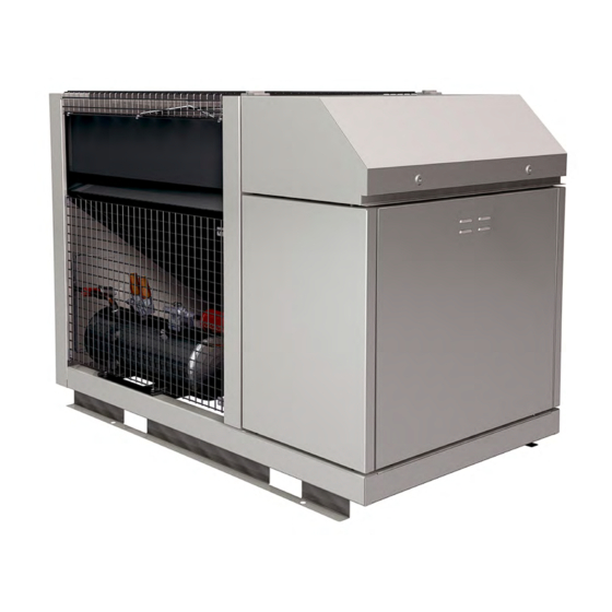
Product description General information about Copeland™ CO refrigeration units Emerson has developed the Copeland CO refrigeration unit to meet primarily the demands of the food retail and food service sectors. It is an air-cooled refrigeration unit that uses the latest Copeland™... -
Page 9: Main Product Features And Dimensions
Main product features and dimensions The refrigeration units covered in these guidelines are released for CO (R744) refrigerant only. They are available in one cabinet size and are always equipped with one fan. The units are designed for medium temperature applications only. The inverter is calculated to drive the compressor in subcritical and transcritical applications. -
Page 10: Product Nameplate
Product nameplate The refrigeration unit nameplate shows model designation and serial number, as well as nominal power and safety pressures. The compressor has its own nameplate with all electrical characteristics. Figure 3: Nameplate of CO units Nomenclature The model designation contains the following technical information about Copeland CO refrigeration units: Figure 4: Nomenclature of CO... -
Page 11: Application Range
Always operate the system with adequate superheat to avoid oil viscosity decrease. Additional measures in system design might help to avoid unacceptable lubrication conditions. For the application envelope, please refer to Select software at www.climate.emerson.com/en-gb. Recommendations for minimum suction superheat – Lubrication conditions 2.6.3... -
Page 12: Pressure Levels Of Co Vs. Other Refrigerants
2.6.4 Pressure levels of CO vs. other refrigerants Figure 5 below compares the evaporating pressures of R744 to those encountered with R410A and R404A. It can be observed that R744 systems will require to operate at much higher pressures than conventional systems. -
Page 13: P&I Diagram For Co Units
P&I diagram for CO units Figure 7: P&I diagram for CO units Position Description Position Description Copeland Stream compressor Compressor inverter Discharge muffler Suction pressure Gas cooler Discharge pressure Flash tank Liquid receiver pressure Filter dryer Suction gas temperature unit Sight glass Suction gas temperature compressor OW5 oil watch... -
Page 14: Main Components Description
Main components description Figure 8: Main components of CO unit 2.8.1 Compressor The compressor is installed in the chamber below the electrical cabinet. The standard delivery is with shut-off valve on discharge, Copeland Protection module, oil watch system connected to one of the sight glass connections. -
Page 15: Liquid Receiver
2.8.3 Liquid receiver The liquid receiver (24.9 litres for the whole range of units) is installed below the gas cooler. It is equipped with a shut-off valve on the outlet and a safety group (2 pressure relief valves 90 bar, connected to a switch-over valve). -
Page 16: Bypass Valve (Bpv)
2.8.6 Bypass valve (BPV) The bypass valve is installed between the flashtank and the suction line to the compressor. Without the bypass valve there is a risk of unacceptably high pressure in the flashtank in case the ambient temperature exceeds 35 °C. The bypass valve is aimed at keeping the flashtank pressure below a set level defined by parameter GC20 (factory-set at 35 bar) at all times. -
Page 17: Housing
Table 7: TS values of the Copeland CO refrigeration units NOTE: The design pressure PS is a safety-related value. The restrictions for reliable operation of the unit are defined by the application envelope which can be found in Select software at www.climate.emerson.com/en-gb. 2.8.8 Housing Copeland CO refrigeration units have a new, unique design. -
Page 18: Exploded View Of The Co Unit
2.8.9 Exploded view of the CO unit Figure 14: Exploded view of the unit AGL_Unit_OME_4MTL_EN_Rev01... -
Page 19: Co Unit Control - General
The controller is factory-set for -10 °C evaporating temperature. To achieve the required temperatures, Emerson recommends to change only the evaporating temperature as the rest of the parameters are already pre-set. NOTE: The other factory settings can be found in Technical Information TI_Unit_CO2_02 Refrigeration Units –... -
Page 20: How To Use The Ipg215D Controller
Position Description Comments Compressor symbol Percentage of analog output for For frequency compressor. Displays the percentage of frequency compressor the analog output driving the inverter. Suction pressure setpoint Current value of suction pressure Displayed when an alarm occurs in suction or gas Alarm cooler section Condensing pressure setpoint... -
Page 21: Parameter Grouping
To enter password: Press the SET key Use the UP and DOWN keys to enter password 12 Press the SET key to confirm password. The following interface will be displayed: Figure 19: Password confirmation Press ENTER to access the Pr2 menu 2.10.2 Parameter grouping The parameters are grouped in sub-menus. -
Page 22: Service" Menu
Press the SET key and use the UP and DOWN keys to modify a value Press the SET key again to store the new value Use the UP and DOWN keys to move to the next parameter NOTE: The Pr2 or Pr1 message is present only in the Pr2 menu. It is possible to modify the level of each parameter by changing Pr2 to Pr1 and vice versa. -
Page 23: How To Check The Values Of Analog Outputs
The following interface will be displayed: Figure 22: "Service" menu 2.10.5 How to check the values of analog outputs Enter the "Service" menu Use the UP and DOWN keys to select the "Analog outputs" sub-menu Press ENTER Figure 23: "Analog outputs" screen Analog Wiring Factory setting... -
Page 24: How To Perform A Maintenance Using The "Compressors Service" Sub-Menus
Digital Wiring Factory setting Description Function output diagram C1 - Inverter 1 Compressor (VF drive) on – Signal "Run" DOC1 X1: 71 / 70 suction - Circuit 1 DOC2 0 - Not used X1: 71 / 72 DOC3 0 - Not used X1: 71 / 73 ALR1 –... -
Page 25: How To Check The Values Of Digital Inputs
Enter the "Compressor service circuit 1" sub-menu Use the UP and DOWN keys to select the "Load status" sub-menu and refer to Figure 25 for screen layout. To erase the running hours of a load: After a maintenance session, it is usually useful to erase the running hours of a load. -
Page 26: How To Check The Values Of The Probes
Digital Wiring Factory setting Description Function input diagram o58 - Safety DIC17 frequency compressor DI17 suction - Circuit 1 o59 - Thermal safety DIC18 of frequency DI18 compressor DIC19 o74 - External alarm 1 DI19 C95 - Operating mode DIC20 DI20 Table 14: Digital inputs overview 2.10.9 How to check the values of the probes... -
Page 27: How To Check The Operating Values Of The Frequency Inverter M200
2.10.12 Controller setting IMPORTANT Never adjust the suction pressure to a value that is outside of the envelope approved by Emerson. To change the suction pressure: Press the PARAM key to access the programming menu Use the UP and DOWN keys to select the Pr1 menu... -
Page 28: How To Reset The Controller To Factory Settings
2.10.14 How to reset the controller to factory settings Enter the "Service" menu Use the UP and DOWN keys to select the "Conf file management" sub-menu Press the SET key. The parameter map will be transferred from "Backup.conf" file to "default_10D.conf"... -
Page 29: Active Alarm(S) Log Menu
There are 4 log files, of which only 3 can be exported: ▪ AccessLog ▪ AlarmLog ▪ ParamLog ▪ ParamAlarmLog The ParamLog and ParamAlarmLog files contain the same variables, but: ▪ the ParamLog file has a fixed sampling rate (5 minutes); ▪... -
Page 30: Ipg215D Controller - Functionality
2.11 IPG215D controller – Functionality The IPG215D controls the complete refrigeration unit. It provides a lot of customization features like alarms and special operating modes. Thanks to the high degree of flexibility, the user can either use the factory-set alarms or set up his own alarms according to the application requirements. The following functionalities are pre-programmed: ▪... -
Page 31: Pumpdown Mode
Factory Parameter Description Level Min value Max value setting SETC1 Compressor Circuit 1 setpoint -15 °C -5 °C -10 °C Differential to be subtracted from SPF1 20 K the compressor setpoint 100 % Compressor capacity during SPF2 (min speed (max speed pumpdown 25 Hz) 60 Hz) -
Page 32: Alarms
Figure 34: Sensoring in subcritical mode 2.11.3.2 Transcritical operation Typically, with gas cooler outlet temperatures above 27 °C (B7 = AIC7 > GC1), the system operates in transcritical mode. ▪ According to the gas cooler outlet temperature detected by the AIC7 (= B7) probe, the high- pressure valve modulates to maintain a pressure that maximizes the COP (Coefficient of Performance). -
Page 33: Figure 36: "Alarm" Key
Press the ALARM key to enter the "Alarm" menu: Figure 36: "Alarm" key The header of the corresponding menu will be flashing. Four alarm menus are available from the display: ▪ Compressor alarms Circuit 1 ▪ Fan alarms Circuit 1 ▪... -
Page 34: Ipg215D Controller - Peripheral Devices
2.12.1 Variable frequency drive M200 The Emerson variable frequency drive M200 has been designed for applications that require flexible integration with systems via industrial Ethernet protocols and fieldbuses, together with advanced RFC-A open-loop motor control. Connection to RS485 networks using Modbus RTU allows for communication with the unit controller. -
Page 35: Compressor Safety
2.13.1 Compressor motor protection Copeland CO refrigeration units are equipped with a Stream 4MTL compressor including Copeland Protection technology. All relevant electrical protection features are covered by the Emerson M200 variable frequency drive. For more details see the M200 Inverter Handbook. -
Page 36: Pressure Relief Valve - High-Pressure Side
The transmitter on the liquid receiver is also used to limit the liquid receiver pressure during operation by means of the bypass valve. Figure 41: Pressure transmitters in the CO unit 2.13.4 Pressure relief valve – High-pressure side A pressure relief valve (120 bar for OME-4MTL-05X to OME-4MTL-09X, 130 bar for OME-4MTL- 12X) is installed in the gas cooler outlet. -
Page 37: Pressure Relief Valve - Liquid Receiver
2.13.5 Pressure relief valve – Liquid receiver There are two pressure relief valves (90 bar) on the liquid receiver, connected through a changeover valve. The pressure relief valve (PRV) protects the unit intermediate pressure side against overpressure (pressure above intermediate pressure side PS). The PRV will reach 100 % of its blow- off capacity when the maximum allowable pressure PS of the unit intermediate pressure side is exceeded by 10 % (opening at 1.0 x PS, maximum capacity at 1.1 x PS). -
Page 38: Oil Level Monitoring Device - Ow5 Traxoil
2.14 Oil level monitoring device – OW5 TraxOil The compressor in the Copeland CO refrigeration unit is equipped with an Emerson OW5 TraxOil oil level monitoring system. This device is intended to prevent the compressor from operating with insufficient oil. The OW5 uses a hall sensor to measure the oil level. Unaffected by foaming oil or light, a magnetic float changes its position according to the oil level. -
Page 39: Installation
Installation WARNING High pressure! Injury to skin and eyes possible! Be careful when opening connections on a pressurized item. Never install the unit at such a height that if the pressure relief valve opens, the gas flow can reach an individual’s head. IMPORTANT Always install the unit in such a way that all installation, commissioning and servicing works can be carried out safely and easily. -
Page 40: Lifting
3.1.3 Lifting Always lift the unit by points marked with red arrows on pictures below. Figure 49: Lifting points for CO units When lifting the unit with slings, always use the spreader bar mounted above the unit to avoid squeezing the unit. Figure 50: Lifting unit with slings and centre of gravity AGL_Unit_OME_4MTL_EN_Rev01... -
Page 41: Refrigeration Piping Connections
Refrigeration piping connections 3.2.1 Refrigeration piping installation and connections WARNING High pressure! Risk of personal injury! The units are pressurized with dry air. Be careful when opening connections on a pressurized item. IMPORTANT Tubing quality! Installation contamination! All interconnecting piping should be of refrigeration grade, clean, dehydrated and must remain capped at both ends until installation. -
Page 42: Brazing Recommendations
Care should be taken to avoid the holding charge releasing too quickly. Be sure tube fitting inner surface and tube outer surface are clean prior to assembly. Both tubes are extended from the refrigeration unit housing, therefore Emerson recommends isolating the housing by using a wet cloth on the copper tubing. -
Page 43: Electrical Connection
Electrical connection WARNING Earth leakage current! Electrical shock hazard! This product includes a three-phase frequency drive. Additional protection devices could be necessary. This must be decided by the electricicty network supplier or by the electrician company which provides the electrical connection. Copeland CO refrigeration units can cause earth leakage currents, both AC and DC, due to the presence of an inverter and an EMC filter in the system. -
Page 44: Electrical Protection Standard (Protection Class)
3.3.3 Electrical protection standard (protection class) ▪ Units: IP class IPX4. ▪ Stream 4MTL compressor terminal box: IP54 according to IEC 34. ▪ Fan: IP54 according to IEC 34. Location & fixings IMPORTANT Dust and dirt contamination! Unit life reduction! The unit should always be installed in a location where clean airflow is ensured. -
Page 45: Figure 55: Unit Mounted On Concrete Slab With Anti-Vibration Pads
units are installed one above the other. Wall mounting brackets are not included in the standard delivery. Figure 55: Unit mounted on concrete slab with anti-vibration pads Other factors to consider in finding a proper installation site are the direction of the prevailing wind and the exposure to sunlight: ▪... -
Page 46: Start-Up & Operation
Start-up & operation WARNING High pressure! Risk of personal injury! Always keep sufficient distance from the pressure relief valve to avoid serious injury in the event of a sudden pressure release. WARNING Hot surfaces! Burning! Do not touch the compressor heads or discharge line as their surfaces can reach high temperatures both during operation and at standstill. -
Page 47: Figure 57: Evacuation Mode
Use the UP and DOWN keys to select the "Evacuation mode" sub-menu Press ENB to enable the evacuation mode (see Figure 57): Figure 57: Evacuation mode Starting the evacuation function: The evacuation mode will start when pressing the ENB key only if all 3 of the following conditions are met: ▪... -
Page 48: Charging Procedure
The factory settings of the system controller take into account the maximum number of permitted starts and stops of the compressor, as well as the running time and minimal downtime. Emerson recommends to change these settings only in exceptional cases, eg, when the liquid line pressure cannot be kept by the factory settings. -
Page 49: Checks Before Starting & During Operation
Checks before starting & during operation IMPORTANT Liquid valves not fully opened! Liquid trap! Both valves on the liquid line should be fully opened in order to prevent liquid trapping. Before a system runs for the first time: ▪ Check that the valves on the liquid line are fully open except for HPV and BPV valves. ▪... -
Page 50: Maintenance & Repair
Hot surfaces! Burning! Do not touch the compressor heads or discharge line as their surfaces can reach high temperatures both during operation and at standstill. CAUTION Unauthorized parts! Unit damage! Only parts authorized by Emerson can be used for maintenance and replacement. 5.2.1 To open the electrical cabinet... -
Page 51: To Open The Compressor Chamber
5.2.2 To open the compressor chamber ▪ Unscrew the two screws located on the top of the compressor chamber cover, unplug the green/yellow grounding cable by pulling, then lift the cover. Figure 60: Opening the compressor chamber 5.2.3 To remove the fan safety grid WARNING Uncovered rotating parts! Personal injuries! Always de-energize the unit before removing the gas cooler fan grid. -
Page 52: Replacing A Compressor
As a general guide, it is advisable to do this at least once every two months. As a general rule and for a clean environment Emerson recommends that the fins be cleaned with liquid detergent diluted with clean water. The refrigeration unit has a well-designed chassis with falling levels towards a large drainage hole, and provided the unit is installed level, any cleaning solution should be able to drain away. -
Page 53: Electrical Installation
NOTE: In order to meet the requirements of the Ecodesign Directive 2009/125/EC with regard to efficient system operation, ensure the heat exchangers remain clean at all times. Electrical installation WARNING Isolating switch "On"! Electrical shock hazard! Turn off the main power supply to de-energise the unit before undertaking any task on electrical equipment. -
Page 54: Regular Maintenance And Check
5.8.2 Regular maintenance and check Once per year: ▪ Visual check according to EN 378. ▪ Leakage test, internal and external. Please follow the instructions: o Remove brass cap (deflector) from pressure relief valves (PRV). o Use a bubble test and check if there is any leak between the connection of the changeover valve and the PRV or if there is any internal leak from the PRV. -
Page 55: Certification & Approval
Certification & approval ▪ Copeland CO Stream refrigeration units comply with the Low Voltage Directive LVD 2014/35/EU. The compliance is verified through harmonized standards: − EN 60335-1: Household and similar electrical appliances – Safety, General Requirements. − EN 60335-2-89: Household and similar electrical appliances – Safety, Particular requirements for commercial refrigerating appliances with an incorporated or remote refrigerant condensing unit or compressor. -
Page 56: Appendix 1: Ipg215D Controller Alarm Menu
Appendix 1: IPG215D controller alarm menu Alarms Circuit 1 Name on Code Description Cause Action Reset Visograph Automatically if the number of activations is less than AL12 in the AL13 time when the input is disabled. Compressors restart working according to the working algorithm. ▪... - Page 57 Alarms Circuit 1 Name on Code Description Cause Action Reset Visograph Automatically as soon as the pressure ▪ If AC1 = REL: or temperature reaches: Minimum pressure Suction pressure or ▪ If AC1 = REL: (temperature) temperature ≤ SETC1 - AL3 SETC1 - AL3 + differential value LAC1 LAC1...
- Page 58 Alarms Circuit 1 Name on Code Description Cause Action Reset Visograph Proper digital input enabled Liquid level alarm (the input is configured as Automatically as soon as the input is Only signalling in Circuit 1 DI1 = 109 liquid level Circuit 1) disabled After delay CDI1 Pre-alarm for...
- Page 59 Compressor alarms Name on Code Description Cause Action Reset Visograph Oil switch load input activation ▪ The corresponding (the input is configured as compressor is turned off DIC = 1 Oil pressostat Compressor (with step compressors all Automatically as soon as the input is compressor Circuit 1) (for each (for each...
- Page 60 Generic alarms Name on Code Description Cause Action Reset Visograph Probe failure Automatically as soon as the probe Probe 1 failure Only signalling alarm restarts working Probe failure Automatically as soon as the probe Probe 2 failure Only signalling alarm restarts working Probe failure Automatically as soon as the probe...
- Page 61 Generic alarms Name on Code Description Cause Action Reset Visograph If value of gas leak detector 1 [2- When value of gas leak detector 1 [2-3- GLeak1 3-4] probe > GLD1 [GLD6- 4] probe ≤ GLD1 – GLD3 PRGLK1 Gas leak pre- Relay set in GLD4 [GLD9- [2-3-4]- GLD11-GLD16] and gas leak...
- Page 62 Compressor with inverter alarms Name on Code Description Cause Action Reset Visograph INVO Oil switch load input activation ▪ The corresponding inverter INVO Inverter safety (for (the input is configured as Automatically as soon as the input is is turned off. (for suction alarm for oil suction...
- Page 63 Gas cooler alarms Name on Code Description Cause Action Reset Visograph (Priority on probe failure alarms) The % of the valve updates every second in order to reach the correct percentage. If the receiver pressure value High pressure on Automatically as soon as the HP REC is between the values GC29 and GC28 –...
-
Page 64: Appendix 2: Temperature / Resistance Curve For Ntc
Appendix 2: Temperature / resistance curve for NTC Temp Resistance Temp Resistance Temp Resistance Temp Resistance Temp Resistance Temp Resistance (Ω) (Ω) (Ω) (Ω) (Ω) (Ω) (°C) (°C) (°C) (°C) (°C) (°C) 329500 67770 17960 5827 2228 973.1 -49.5 320200 -19.5 66170 10.5... - Page 65 Temp Resistance Temp Resistance Temp Resistance Temp Resistance Temp Resistance Temp Resistance (Ω) (Ω) (Ω) (Ω) (Ω) (Ω) (°C) (°C) (°C) (°C) (°C) (°C) -32.5 126550 -2.5 30390 27.5 9112.5 57.5 3266.5 87.5 1354.5 123300 29730 8944 3215 1336 -31.5 120200 -1.5 29105...
-
Page 66: Appendix 3: Temperature / Resistance Curve For Ptc
Appendix 3: Temperature / resistance curve for PTC Temp Resistance Temp Resistance Temp Resistance Temp Resistance Temp Resistance Temp Resistance Temp Resistance (Ω) (Ω) (Ω) (Ω) (Ω) (Ω) (Ω) (°C) (°C) (°C) (°C) (°C) (°C) (°C) 420.6 772.8 1240.5 1524.5 1841 -64.5 423.57... - Page 67 Temp Resistance Temp Resistance Temp Resistance Temp Resistance Temp Resistance Temp Resistance Temp Resistance (Ω) (Ω) (Ω) (Ω) (Ω) (Ω) (Ω) (°C) (°C) (°C) (°C) (°C) (°C) (°C) -47.5 522.35 -17.5 692.2 12.5 895.4 42.5 1132.05 72.5 1402.1 102.5 1705.75 132.5 2028 524.9...
-
Page 68: Appendix 4: Overview Tables - Regulation 2015/1095/Eu
Appendix 4: Overview tables – Regulation 2015/1095/EU AGL_Unit_OME_4MTL_EN_Rev01... - Page 69 AGL_Unit_OME_4MTL_EN_Rev01...
-
Page 70: Appendix 5: List Of Tables And Figures
Appendix 5: List of tables and figures Tables Table 1: CO refrigeration unit technical data ..................4 Table 2: CO refrigeration unit features ....................4 Table 3: Qualified refrigerant and oil ....................6 Table 4: Legend of the P&I diagram for CO units ................ -
Page 71: Disclaimer
3. Emerson does not assume responsibility for the selection, use or maintenance of any product. Responsibility for proper selection, use and maintenance of any Emerson product remains solely with the purchaser or end user. - Page 72 The Emerson logo is a trademark and service mark of Emerson Electric Co. Emerson Climate Technologies Inc. is a subsidiary of Emerson Electric Co. Copeland is a registered trademark and Copeland Scroll is a trademark of Emerson Climate Technologies Inc.. All other trademarks are property of their respective owners.