
Related Manuals for Emerson Copeland OMTE-76D


Summary of Contents for Emerson Copeland OMTE-76D
- Page 1 Application Guidelines Copeland Large Outdoor ™ Refrigeration Units OMTE-76D to OMTE-152D OLE-49 & OLTE-82D...
-
Page 2: Table Of Contents
About these guidelines ....................1 Safety instructions ..................1 1.1 Icon explanation ....................1 1.2 Saf ety statements....................1 1.3 General instructions .................... 2 Product description ..................3 2.1 General information about Copeland™ LOCU refrigeration unit ......... 3 2.2 EU Ecodesign Directive 2009/125/EC..............3 2.3 Main product features and dimensions.............. - Page 3 2.18.3 Location of the "Hot Key" plug connection on the XCM25D controller ....24 2.18.4 How to program a "Hot Key" from the controller (upload) .......24 2.18.5 How to program the controller using an Emerson "Hot Key" (download) ...24 2.19 Troubleshooting – Alarm history................25 2.20 Compressor motor protection ................25...
- Page 4 3.3.2 Maximum operating currents for cable selection ...........31 3.3.3 Electrical protection standard (protection class)..........32 3.4 Location & fixings ....................32 Start-up & operation..................33 4.1 Evacuation .......................33 4.2 Charging procedure ...................33 4.2.1 Refrigerant charging procedure ..............33 4.2.2 Charging level in liquid receiver ..............34 4.2.3 Oil charging procedure ................34 4.3 Rotation direction of scroll compressors ..............35...
-
Page 6: About These Guidelines
For relevant standards please ref er to the Manufacturer’s Declaration, available at www.climate.emerson.com/en- These instructions should be retained throughout the lif etime of both the compressor and the ref rigeration unit. -
Page 7: General Instructions
General instructions WARNING Pressurized system! Serious personal injuries and/or system breakdown! Accidental system start before complete set-up must be avoided. Never leave the system unattended without locking it out electrically when it is on vacuum and has no ref rigerant charge, when it has a holding charge of nitrogen, or when the compressor service valves are closed. -
Page 8: Product Description
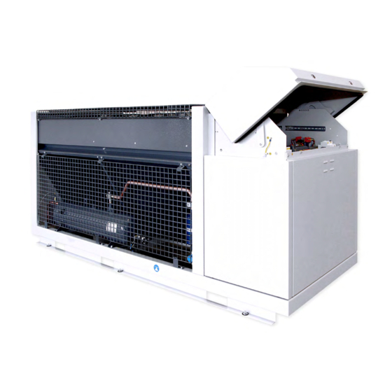
General information about Copeland™ LOCU refrigeration unit Emerson has developed the Copeland LOCU ref rigeration unit to meet the demands of the food retail and f ood service sectors. It is an air-cooled refrigeration unit that uses the latest Copeland patented scroll technology as the main driver and has electronic protection and diagnostics features built in the high-quality chassis. -
Page 9: Figure 2: Outer Dimensions Of Models Omte-76D, Omte-90D & Ole-49
Outer dimensions Net weight Gross weight Unit length/width/height with (kg) (kg) closed cover (mm) OMTE-76D OMTE-90D 1581 / 900 / 1069 OLE-49 OMTE-152D 2303 / 900 / 1150 OLTE-82D Table 2: LOCU features The f igures hereafter shows the overall physical dimensions of the LOCU refrigeration units: Figure 2: Outer dimensions of models OMTE-76D, OMTE-90D &... -
Page 10: Product Nameplate
Product nameplate The ref rigeration unit nameplate shows model designation and serial number, as well as locked rotor amps, maximum rated current, safety pressures and weight. The compressor has its own nameplate with all electrical characteristics. Figure 4: Nameplate LOCU units Nomenclature The model designation contains the f ollowing technical inf ormation about Copeland LOCU ref rigeration units:... -
Page 11: Application Range
For application envelopes, please refer to the compressor application envelopes which can be found in Copeland Select software, available at www.climate.emerson.com/en-gb. LOCU ref rigeration units can be used at ambient temperatures down to -15 °C. The application envelopes of the units must be respected under all operating conditions. -
Page 12: P&I Diagrams
P&I diagrams 2.8.1 OMTE-76D & OMTE-90D units Figure 6: P&I diagram for OMTE-76D & OMTE-90D models Position Description Comments P1 Suction pressure transducer (AI1) PPR15 P2 Condensing pressure transducer (AI2) PPR30 DLT Discharge line temperature sensor (AI3) NTC 86K Ambient temperature sensor (AI6) NTC 10K Liquid receiver with liquid level watch LW4-L120 Alco Controls... -
Page 13: Omte-152D Units
2.8.2 OMTE-152D units Figure 7: P&I diagram for OMTE-152D models Position Description Comments P1 Suction pressure transducer (AI1) PPR15 P2 Condensing pressure transducer (AI2) PPR30 DLT Discharge line temperature sensor (AI3) NTC 86K Ambient temperature sensor (AI6) NTC 10K Liquid receiver with liquid level watch LW4-L120 Alco Controls TT >>... -
Page 14: Ole-49 Units
2.8.3 OLE-49 units Figure 8: P&I Diagram OLE-49 models Position Description Comments P1 Suction pressure transducer (AI1) PPR15 P2 Condensing pressure transducer (AI2) PPR30 DLT Discharge line temperature sensor (AI3) NTC 86K TT >> DLT Discharge line thermostat 130 °C Liquid receiver with liquid level watch LW4-L120 Alco Controls Ambient temperature sensor (AI6) -
Page 15: Olte-82D Units
2.8.4 OLTE-82D units Figure 9: P&I diagram for OLTE-82D models Position Description Comments P1 Suction pressure transducer (AI1) PPR15 P2 Condensing pressure transducer (AI2) PPR30 DLT Discharge line temperature sensor (AI3) NTC 86K Ambient temperature sensor (AI6) NTC 10K Liquid receiver with liquid level watch LW4-L120 Alco Controls TT >>... -
Page 16: Main Components Description
Main components description Figure 10: Main components of LOCU units Bill of material 501 – General description 2.9.1 The standard bill of material f or OMTE, OLE & OLTE units is 501. In general, these units have an air-cooled condenser with 1 or 2 EC f ans for condensing temperature control. For OMTE and OLTE units, a Tandem set of 2 scroll compressors (ZB** for OMTE, ZF** f or OLTE) provides the required cooling capacity. -
Page 17: Electrical Cabinet
2.9.4 Electrical cabinet Figure 11: Electrical cabinet 2.9.5 Condenser fan(s) The condensers of the LOCU ref rigeration units are equipped with electronically-commutated (EC) external rotor motor with integrated EC controller: ▪ Integrated motor contactor, active temperature management. ▪ Interf erence emissions EN 61000-6-3. ▪... -
Page 18: Xcm25D Electronic Controller - Features
2.10 XCM25D Electronic controller – Features The XCM25D controller is designed to be a powerf ul, f lexible controller f or use in multiple applications. It has been developed f or condensing units and allows the adjustment of all relevant parameters by the user. -
Page 19: Modbus Communication
The XCM25D controller can communicate via Modbus (RS-485) connection to provide all running data. Additional commands can also be activated through Modbus connection. The Modbus map is available on request from the Application Engineering department at Emerson. A pre-configured X-Web Supervisor device is also available and allows easy handling and connectivity with the XCM25D controller. - Page 20 compressor top cap connected to the injection valve which allows individual regulation f or each compressor. On digital models a solenoid valve (normally closed NC) is energized in parallel to the digital modulation solenoid valve to avoid injection during part -load conditions. The discharge line protection is achieved with discharge line thermostats (B11 &...
-
Page 21: Xcm25D Electronic Controller - Programming
2.11 XCM25D Electronic controller – Programming CAUTION Low refrigerant charge! Compressor damage! Never energize the unit/controller without minimum ref rigerant system charge. There is a risk of malf unction of the controller in deep vacuum operation which can cause compressor damage. 2.11.1 Programming the local display Figure 16: Local display Mode... -
Page 22: Remote Display Ccm60
There are two connection terminals on the back of the remote display (+ and -). NOTE: Emerson recommends using a shielded cable twisted pair 2 x 0.5 mm². The device must be connected to the VNR-terminal on the unit controller according to the polarity. -
Page 23: Double Commands - Entering Programming Level 1 "Pr1
2.11.4 Double commands – Entering programming level 1 "Pr1" Press simultaneously for about 3 seconds to lock (PoF) or unlock (Pon) the keyboard. Press simultaneously to leave the programming mode or menu. On submenus rtC and EEV this combination allows to go back to the previous level. Press simultaneously for about 3 seconds to access the first level of programming mode. -
Page 24: Fast Access Menu
2.11.7 Fast access menu The f ast access menu contains the list of probes and some values that are automatically evaluated by the board such as the superheat and the percentage of valve opening. "nP" or "noP" stands f or "Probe not present" or "Value not evaluated". "Err" means "Value out of range"... -
Page 25: Parameters Level 1 - Required Settings
2.13 Parameters level 1 – Required settings The XCM25D is preconfigured to reduce the required settings on job -site to a minimum. In most cases it will not be necessary to enter programming level 2 "Pr2". Table 17 gives an overview of the parameters available in programming level 1 "Pr1". -
Page 26: Rescue Mode (Emergency Mode)
The regulation starts when the suction pressure (AI1) increases and reaches the value (C16-C17/2+(C17*C24)/100). Within the adjustment range (C16-C17/2 ~ C16+C17/2) the digital scroll compressor is activated in PWM mode according to the value of the control variable. When the pressure is higher than (C16+C17/2) then the TRIAC output is at maximum capacity. When the pressure is lower than (C16+C17/2) but higher than (C16-C17/2) the digital compressor modulates the capacity according to the proportional band. -
Page 27: Ps1 - Setpoint Adjustment Of Low-Pressure Switch In Rescue Mode
NOTE: The SB1 button (test button) allows to by-pass the low-pressure device B10. It might be useful under certain system conditions to manually let the compressors run. Only qualified and trained technicians should activate the compressors manually. Keep system pressures and temperatures within acceptable limits. -
Page 28: Heat Recovery Mode - Optional
2.16 Heat recovery mode – Optional OMTE units can be ordered with special BOM 502 for simple heat recovery integration. A unit in this special version is mechanically pre-arranged with piping connections f or an additional heat exchanger for desuperheating. Figure 22: Piping arrangement for heat recovery The heat recovery f eature is active by default. -
Page 29: Reset To Factory Settings - Emerson "Hot Key
Application Engineering representative. 2.18.2 Applicable hot key for LOCU units with XCM25D controller The Emerson "Hot Key" DK00000300 can be used for uploading and downloading of parameter lists. Copeland ident number 3226456. Figure 24: Emerson "Hot Key"... -
Page 30: Troubleshooting - Alarm History
NOTE: The message "Err" is displayed in case of a failed programming operation. In this case turn the unit off, then on again to restart the download, or remove the "Hot Key" to abort the operation. 2.19 Troubleshooting – Alarm history The controller records the total number of alarm activations (max 50) in the alarm menu –... -
Page 31: Ambient Temperature Sensor
2.22.2 Ambient temperature sensor An ambient temperature sensor supplied by Emerson is connected to the electronic controller. This temperature sensor has several f unctionalities like emergency mode control, lower f an speed limitation and crankcase heater control. 2.22.3 Refrigerant level control – Leak detection device The liquid receiver is equipped with an external liquid level watch LW4-L120 from Alco Controls. -
Page 32: Installation
Installation WARNING High-pressure! Injury to skin and eyes possible! Be careful when opening connections on a pressurized item. IMPORTANT The installation location must be selected in accordance with local workplace saf ety regulations. Copeland LOCU refrigeration units are delivered with a holding charge of neutral gas. The ref rigeration unit should be located in such a place to prevent any dirt, dust, plastic bags, leaves or papers from covering the condenser and its fins. -
Page 33: Refrigeration Piping Connections
Always lift the unit by points marked with yellow arrows on pictures below. Figure 27: Lifting points in LOCU Figure 28: Centre of gravity Refrigeration piping connections 3.2.1 Refrigeration piping installation WARNING High pressure! Risk of personal injury! The units are pressurized with dry air. -
Page 34: Connection Sizes
1/200 to 1/250. Upper and lower oil traps, double risers and reduced pipe diameters may be required f or suction lines where long vertical risers cannot be avoided. All pipes should be adequately supported to prevent sagging which can create oil traps. The recommended pipe clamp support distance is shown in Table 21 below: Max distance between Tube size... -
Page 35: Brazing Recommendations
▪ Be sure tube f itting inner surface and tube outer surface are clean prior to assembly. ▪ Both tubes are extended f rom the ref rigeration unit housing, therefore Emerson recommends isolating the housing by using a wet cloth on the copper tubing. -
Page 36: Brazing Procedure
3.2.4 Brazing procedure Ref er to Figure 31 and procedure below for the brazing of the tubes: ▪ Fit the copper tube into the unit tube. ▪ Heat area 1. As the tube approaches brazing temperature, ▪ Heat area 2 until braze temperature is attained. It is necessary to heat the tube evenly. -
Page 37: Electrical Protection Standard (Protection Class)
3.3.3 Electrical protection standard (protection class) ▪ Units: IPX4. ▪ Scroll compressors: IP21 according to IEC 34. ▪ Fan: IP44 according to IEC 34. ▪ Solenoid valve coils: IP65 according to DIN 43650. Location & fixings IMPORTANT Dust and dirt contamination! Unit life reduction! The unit should always be installed in a location that ensures clean air f low. -
Page 38: Start-Up & Operation
Start-up & operation WARNING Diesel effect! System explosion! The mixture of air and oil at high temperature can lead to an explosion. Avoid operating with air. Bef ore commissioning, ensure that all valves on the refrigeration unit are fully opened. Only qualified personal and certified companies are allowed to carry out installation, commissioning, service and maintenance work. -
Page 39: Charging Level In Liquid Receiver
Copeland LOCU refrigeration units are pre-charged with oil. After commissioning, the oil level should be checked and topped up if necessary. As mentioned in section 2.6.1 "Qualified refrigerants and oils", Emerson recommends charging with one of the following oil types: ▪... -
Page 40: Rotation Direction Of Scroll Compressors
Figure 34: Oil charging service ports The compressors in OMTE-152D and OLTE-82D units are equipped with an OM3 TraxOil oil management device from Alco Controls. The compressors will be switched off in case of insufficient oil level. The TraxOil will inject an adequate quantity of oil if required. It is important to have a suf ficient quantity of oil in the system to ensure proper functionality of the oil management system. -
Page 41: Pressure Fluctuations In Case Of Digital Unit
After start-up and when operation conditions have stabilised: ▪ It is recommended to check the oil level in the compressors and to add oil if necessary to ensure a suf f icient oil level (halfway up the sight glass). ▪ The f ollowing should also be checked: ✓... -
Page 42: Maintenance & Repair
Maintenance & repair WARNING Conductor cables! Electrical shock hazard! Follow the lockout/tag out procedure and the national regulations before undertaking any maintenance or service work on the system. Screwed electrical connections must be used in all applications. Ref er to original equipment wiring diagrams. -
Page 43: To Remove The Fan Safety Grid
5.1.3 To remove the fan safety grid WARNING Uncovered rotating parts! Personal injuries! Always de-energize the unit bef ore removing the condenser f an grid. Never start the unit or run the f an with no saf ety grid on the fan. ▪... -
Page 44: Electrical Terminations
As a general guide, it is advisable to do this at least once every two months. As a rule, and f or a clean environment, Emerson recommends that the f ins be cleaned with liquid detergent diluted with clean water. The ref rigeration unit has a well-designed chassis, and provided the unit is installed level, any cleaning solution should be able to drain away. -
Page 45: Condenser Fans & Motors
However, pipe plugs with sealant applied at the factory are not to be retorqued, as this would break the seal and create a leak path in the cured sealant. Torque (Nm) Rotalock 1/2" x 5/8" Brazed connection Rotalock 5/8" x 5/8" Brazed connection Rotalock 7/8"... -
Page 46: Certification & Approval
Certification & approval ▪ Copeland LOCU refrigeration units comply with the Low Voltage Directive LVD 2014/35/EU. The compliance is verified through harmonized standards: − EN 60335-1: Household and similar electrical appliances – Safety, General Requirements. − EN 60335-2-89: Household and similar electrical appliances – Safety, Particular requirements f or commercial refrigerating appliances with an incorporated or remote refrigerant condensing unit or compressor. -
Page 47: Appendix 1: Parameter List Level 1 (Pr1)
Appendix 1: Parameter list level 1 (Pr1) Factory settings Parameter Description Range OMTE OLTE Compressor cut-in pressure C02 to C04 setpoint Compressor cut-out pressure C03 to C01 setpoint Ref rigerant selection for R404A (0-404) - R134A (2-134) - R407A (5-07A) 8-R449A regulation R407F (6-07F) - R448A (7-48A) - R449A (8-49A) -
Page 48: Appendix 2: Alarm Menu
Appendix 2: Alarm menu Code Description Cause Action Reset Only in digital unit - Compressor is AI1 error (Probe 1 / Suction Probe failure or out of activated according to C23, and Automatically as soon as the probe restarts pressure transducer failure alarm) range compressor on &... - Page 49 Code Description Cause Action Reset Power supply phase loss happened H12 Hold "start" button for 5 sec or manual power off Lost phase lockout The compressor will lock out times within one hour and on (3-phase units) Incorrect phase Phase sequence lockout sequence (3-phase The compressor will lock out Manual power off and on...
- Page 50 Code Description Cause Action Reset Hold "start" button for 5 sec or manual power off Overvoltage happened The compressor will lock out (if H17 and on (if H17 equal to 0, compressor Overvoltage lockout H17 times within one equal to 0, no compressor lockout) automatically start when voltage is back within hour acceptable range and H16 delay time-out)
- Page 51 Code Description Cause Action Reset Discharge line Hold "start" button for 5 sec or manual power off Discharge line temperature lockout temperature overheat The compressor will lock out (if D26 and on (if D26 equal to 0, compressor starts compressor # 1 happened D26 times equal to 0, no compressor lockout) automatically when discharge line temperature...
- Page 52 Code Description Cause Action Reset Number of cold-start alarms due to suction pressure exceeds parameter D34 setting Digital compressor turns off and is Hold "start" button for 5 sec or manual power off Cold-start lockout alarm or number of cold start locked out and on alarms due to...
- Page 53 Code Description Cause Action Reset Dif ferent probes (P3, P4, P5, P6, P7) have the same configuration. For example, Probe configuration error Correct the configuration Board must be reset A13 = Ambient temp (NTC 10 K), A15 = Ambient temp (NTC 10 K) Dif ferent digital inputs DI (DI1, DI2, DI3) have...
-
Page 54: Appendix 3: Temperature / Resistance Curve For B7 Sensor (Customer Option)
Appendix 3: Temperature / resistance curve for B7 Sensor (customer option) R25 = 10 kΩ B25/85 = 3435 K Temp. Resistance Temp. Resistance Temp. Resistance Temp. Resistance Temp. Resistance Temp. Resistance (°C) (kΩ) (°C) (kΩ) (°C) (kΩ) (°C) (kΩ) (°C) (kΩ) (°C) (kΩ) -
Page 55: Appendix 4: List Of Tables And Figures
Figure 22: Piping arrangement for heat recovery..............23 Figure 23: Heat recovery implementation................23 Figure 24: Emerson "Hot Key" ................... 24 Figure 25: Location of "Hot Key" plug connection ..............24 Figure 26: Maximum stacking loads for transport and storage ..........27... - Page 56 Figure 27: Lifting points in LOCU ..................28 Figure 28: Centre of gravity ....................28 Figure 29: Connection ports on suction & liquid lines ............. 29 Figure 30: Brazing – Sectional view ..................30 Figure 31: Suction tube brazing areas ................. 31 Figure 32: Fixing dimensions and distances in mm..............
-
Page 57: Disclaimer
3. Emerson does not assume responsibility for the selection, use or maintenance of any product. Responsibility for proper selection, use and maintenance of any Emerson product remains solely with the purchaser or end user. - Page 58 The Emerson logo is a trademark and service mark of Emerson Electric Co. Emerson Climate Technologies Inc. is a subsidiary of Emerson Electric Co. Copeland is a registered trademark and Copeland Scroll is a trademark of Emerson Climate Technologies Inc.. All other trademarks are property of their respective owners.