beautypg.com
Manuals
Brands
Emerson Manuals
Refrigerator
Copeland OLE-49
Emerson Copeland OLE-49 Manuals
Manuals and User Guides for Emerson Copeland OLE-49. We have
1
Emerson Copeland OLE-49 manual available for free PDF download: Application Manuallines
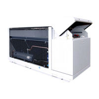
Emerson Copeland OLE-49 Application Manuallines (58 pages)
Large Outdoor Refrigeration Units
Brand:
Emerson
| Category:
Refrigerator
| Size: 3.18 MB
Table of Contents
Table of Contents
2
Safety Statements
6
About These Guidelines
6
Icon Explanation
6
Safety Instructions
6
General Instructions
7
Product Description
8
General Information about Copeland™ LOCU Refrigeration Unit
8
EU Ecodesign Directive 2009/125/EC
8
Main Product Features and Dimensions
8
Figure 1: Front View of the Copeland LOCU Refrigeration Unit
8
Figure 2: Outer Dimensions of Models OMTE-76D, OMTE-90D & OLE-49
9
Figure 3: Outer Dimensions of Models OMTE-152D & OLTE-82D
9
Product Nameplate
10
Nomenclature
10
Figure 4: Nameplate LOCU Units
10
Figure 5: Nomenclature LOCU Units
10
BOM Variations
11
PED Category
11
Application Limits
11
Qualified Refrigerants and Oils
11
Application Range
11
P&I Diagrams
12
OMTE-76D & OMTE-90D Units
12
Figure 6: P&I Diagram for OMTE-76D & OMTE-90D Models
12
OMTE-152D Units
13
Figure 7: P&I Diagram for OMTE-152D Models
13
Figure 8: P&I Diagram OLE-49 Models
14
OLE-49 Units
14
OLTE-82D Units
15
Figure 9: P&I Diagram for OLTE-82D Models
15
Main Components Description
16
Bill of Material 501 - General Description
16
Bill of Material 502 - General Description
16
Compressor
16
Figure 10: Main Components of LOCU Units
16
Figure 12: LOCU Unit Housing
17
Figure 11: Electrical Cabinet
17
Housing
17
Condenser Fan(S)
17
Electrical Cabinet
17
XCM25D Electronic Controller - Features
18
Description
18
Functionality
18
Figure 13: XCM25D Electronic Controller
18
Modbus Communication
19
Main Control & Safety Features
19
Figure 14: XCM25D Controller Functionality Overview
19
Figure 15: Modbus Port and Termination Jumpers
19
XCM25D Electronic Controller - Programming
21
Programming the Local Display
21
Figure 16: Local Display
21
Remote Display CCM60
22
Single Commands
22
Figure 17: Remote Display Front Panel Mounting
22
Figure 18: VNR Connection for the Remote Display
22
Entering Programming Level 2 "Pr2
23
How to Program the Parameters (Pr1 and Pr2)
23
Double Commands - Entering Programming Level 1 "Pr1
23
Fast Access Menu
24
Controller Keyboard
24
How to Lock the Keyboard
24
How to Unlock the Keyboard
24
Parameters Level 1 - Required Settings
25
Digital Operation
25
Figure 19: Digital Operation
25
Rescue Mode (Emergency Mode)
26
Functionality
26
Figure 20: Rescue Mode - Control Panel Front and Bottom Views
26
PS1 - Setpoint Adjustment of Low-Pressure Switch in Rescue Mode
27
Fan Operation in Rescue Mode
27
Figure 21
27
Figure 22: Piping Arrangement for Heat Recovery
28
Figure 23: Heat Recovery Implementation
28
Pumpdown
28
Heat Recovery Mode - Optional
28
How to Program a "Hot Key" from the Controller (Upload)
29
Figure 24: Emerson "Hot Key
29
How to Program the Controller Using an Emerson "Hot Key" (Download)
29
Figure 25: Location of "Hot Key" Plug Connection
29
Location of the "Hot Key" Plug Connection on the XCM25D Controller
29
Applicable Hot Key for LOCU Units with XCM25D Controller
29
How to Save Factory Settings or User Settings
29
Reset to Factory Settings - Emerson "Hot Key
29
Troubleshooting - Alarm History
30
Compressor Motor Protection
30
System Pressure Protection
30
High-Pressure Safety Switch
30
Low-Pressure Safety Switch
30
Other Inputs of the XCM25D Controller
30
Heat Recovery Mode
30
Alarm Output (DO5) of the XCM25D Controller
31
Refrigerant Level Control - Leak Detection Device
31
Ambient Temperature Sensor
31
Fan Failure - Fan Feedback
31
Installation
32
Refrigeration Unit Handling
32
Transport and Storage
32
Weights
32
Lifting
32
Figure 26: Maximum Stacking Loads for Transport and Storage
32
Figure 28: Centre of Gravity
33
Refrigeration Piping Connections
33
Figure 27: Lifting Points in LOCU
33
Refrigeration Piping Installation
33
Connection Sizes
34
Figure 29: Connection Ports on Suction & Liquid Lines
34
Brazing Recommendations
35
Figure 30: Brazing - Sectional View
35
Figure 31: Suction Tube Brazing Areas
36
Maximum Operating Currents for Cable Selection
36
Power Supply Connections
36
Brazing Procedure
36
Electrical Connection
36
Electrical Protection Standard (Protection Class)
37
Location & Fixings
37
Figure 32: Fixing Dimensions and Distances in MM
37
Start-Up & Operation
38
Evacuation
38
Charging Procedure
38
Refrigerant Charging Procedure
38
Figure 33: Charging Level in Liquid Receiver
39
Charging Level in Liquid Receiver
39
Oil Charging Procedure
39
Rotation Direction of Scroll Compressors
40
Maximum Compressor Cycle
40
Checks before Starting & During Operation
40
Figure 34: Oil Charging Service Ports
40
Pressure Fluctuations in Case of Digital Unit
41
Figure 36: Opening the Compressor Chamber
42
Figure 35: Position of the Locks
42
To Open the Electrical Cabinet
42
To Open the Compressor Chamber
42
Opening the Unit Housing
42
Maintenance & Repair
42
To Remove the Fan Safety Grid
43
To Access the Inner Parts of the Condenser
43
Replacing a Compressor
43
Figure 37: Opening the Fan Safety Grid
43
Figure 38: Accessing the Inner Parts of the Unit
43
Routine Leak Testing
44
Condenser Fins
44
Electrical Terminations
44
Condenser Fans & Motors
45
Certification & Approval
46
Dismantling & Disposal
46
Appendix 1: Parameter List Level 1 (Pr1)
47
Appendix 2: Alarm Menu
48
Appendix 3: Temperature / Resistance Curve for B7 Sensor (Customer Option)
54
Appendix 4: List of Tables and Figures
55
Disclaimer
57
Related Products
Emerson Copeland EazyCool OME-4MTL-05X
Emerson Copeland EazyCool OME-4MTL-07X
Emerson Copeland EazyCool OME-4MTL-09X
Emerson Copeland OMTE-76D
Emerson Copeland OMTE-152D
Emerson Copeland OLTE-82D
Emerson Copeland OME-4MTL-12X
Emerson Copeland EazyCool OLQ-24V-Nxx-TWD Series
Emerson Copeland EazyCool OLQ-11-TFD
Emerson Copeland EazyCool OLQ-48V-TWD
Emerson Categories
Controller
Control Unit
Transmitter
Measuring Instruments
Fan
More Emerson Manuals