
Related Manuals for Asus AAEON MIPICSI Camera RVP Converter Kit


Summary of Contents for Asus AAEON MIPICSI Camera RVP Converter Kit
- Page 1 MIPICSI Camera RVP Converter Kit UP Expansion Module User’s Manual 1st Ed Last Updated: June 16, 2023...
- Page 2 Copyright Notice This document is copyrighted, 2023. All rights are reserved. The original manufacturer reserves the right to make improvements to the products described in this manual at any time without notice. No part of this manual may be reproduced, copied, translated, or transmitted in any form or by any means without the prior written permission of the original manufacturer.
- Page 3 Acknowledgement Microsoft®, Windows® are registered trademarks of Microsoft Corp • Ubuntu and Canonical are registered trademarks of Canonical Ltd. • Linux is the registered trademark of Linus Torvalds in the U.S. and other • countries All other products’ name or trademarks are properties of their respective owners. Preface...
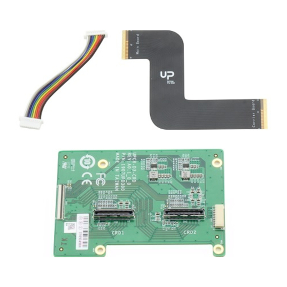
- Page 4 Packing List Before setting up your product, please make sure the following items have been shipped: Item Quantity RVP Converter Board ⚫ FPC Cable ⚫ Power Cable ⚫ Screws/Stud Pack ⚫ If any of these items are missing or damaged, please contact your distributor or sales representative immediately.
- Page 5 About this Document This User’s Manual contains all the essential information, such as detailed descriptions and explanations on the product’s hardware and software features (if any), its specifications, dimensions, jumper/connector settings/definitions, and driver installation instructions (if any), to facilitate users in setting up their product. Users may refer to the product page at AAEON.com for the latest version of this document.
- Page 6 Safety Precautions Please read the following safety instructions carefully. It is advised that you keep this manual for future references All cautions and warnings on the device should be noted. Make sure the power source matches the power rating of the device. Position the power cord so that people cannot step on it.
- Page 7 If any of the following situations arises, please the contact our service personnel: Damaged power cord or plug Liquid intrusion to the device iii. Exposure to moisture Device is not working as expected or in a manner as described in this manual The device is dropped or damaged Any obvious signs of damage displayed on the device...
- Page 8 FCC Statement This device complies with Part 15 FCC Rules. Operation is subject to the following two conditions: (1) this device may not cause harmful interference, and (2) this device must accept any interference received including interference that may cause undesired operation.
- Page 9 China RoHS Requirements (CN) 产品中有毒有害物质或元素名称及含量 AAEON Main Board/ Daughter Board/ Backplane 有毒有害物质或元素 部件名称 铅 汞 镉 六价铬 多溴联苯 多溴二苯醚 (Pb) (Hg) (Cd) (Cr(VI)) (PBB) (PBDE) 印刷电路板 ○ ○ ○ ○ 及其电子组件 外部信号 ○ ○ ○ ○ 连接器及线材 O:表示该有毒有害物质在该部件所有均质材料中的含量均在 SJ/T 11363-2006 标准规定的限量要求以下。 X:表示该有毒有害物质至少在该部件的某一均质材料中的含量超出...
- Page 10 China RoHS Requirement (EN) Poisonous or Hazardous Substances or Elements in Products AAEON Main Board/ Daughter Board/ Backplane Poisonous or Hazardous Substances or Elements Hexavalent Polybrominated Polybrominated Component Lead Mercury Cadmium Chromium Biphenyls Diphenyl Ethers (Pb) (Hg) (Cd) (Cr(VI)) (PBB) (PBDE) PCB &...
-
Page 11: Table Of Contents
Table of Contents Chapter 1 - Product Specifications..................1 Specifications ......................2 Chapter 2 – Hardware Information ..................3 Dimensions ....................... 4 Board Layout ......................5 List of Jumpers and Connectors ................6 2.3.1 CRD1 (CN2) ....................7 2.3.2 CRD2 (CN3) ....................8 2.3.3 Power (CN4) .................... - Page 12 3.3.6 Testing AR0234 Sensor(s) ................. 28 3.3.6.1 Video Loopback Setup ..............29 3.3.7 OpenVINO Python Demo Setup ............. 31 3.3.8 Intel® Deep Learning Streamer Setup ..........32 3.3.9 FAQ ....................... 33 Appendix A –Connectors ...................... 34 Connectors......................35 Preface...
-
Page 13: Chapter 1 - Product Specifications
Chapter 1 Chapter 1 - Product Specifications... -
Page 14: Specifications
Specifications System Power: 5V/2A in from Wafer MIPI-CSI in: 4-Lane + Clock from Camera Module Connector x 2 MIPI-CSI Out: 61-pin FPC Connector x 1 Dimensions 3.3" x 2.4" (85mm x 61mm) Net Weight 0.1 lb. (0.04Kg) Gross Weight 0.13 lb. (0.06Kg) Operating Temperature 32°F ~ 140°F (0°C ~ 60°C), 0.5m/s airflow Operating Humidity... -
Page 15: Chapter 2 - Hardware Information
Chapter 2 – Hardware Information Chapter 2... -
Page 16: Dimensions
Dimensions Chapter 2 – Hardware Information... -
Page 17: Board Layout
Board Layout Chapter 2 – Hardware Information... -
Page 18: List Of Jumpers And Connectors
List of Jumpers and Connectors Label Functional Description CRD1 CRD2 POWER Chapter 2 – Hardware Information... -
Page 19: Crd1 (Cn2)
2.3.1 CRD1 (CN2) Signal Description Signal Description ISH_INT_GP_CRD_GSB CRD1_A0 MGCLKOUT2 CRD1_A1 MGCLKOUT0 GPPC_PRIVACY_CAM1 GPPC_CAM1_CLK_EN CAM1_RST# CRD1_PWREN GPPC_STROBE_CAM1 I2C1_SDA CSI_A_CK_DN I2C1_SCL CSI_A_CK_DP GPPC_CAM1_SYNCIN GPPC_CAM1_SYNCOUT CSI_A_D0_DN CSI_A_D0_DP CSI_A_D1_DN Chapter 2 – Hardware Information... -
Page 20: Crd2 (Cn3)
Signal Description Signal Description CSI_A_D1_DP 1.8V 1.8V CSI_B_CK_DN CSI_B_CK_DP CSI_B_D1_DN CSI_B_D1_DP 3.3V CSI_B_D0_DN 3.3V CSI_B_D0_DP 3.3V 2.3.2 CRD2 (CN3) Signal Description Signal Description CRD2_A0 MGCLKOUT3 CRD2_A1 Chapter 2 – Hardware Information... - Page 21 Signal Description Signal Description MGCLKOUT1 PRIVACY_CAM2 GPPC_CAM2_CLK_EN CAM2_RST# CRD2_PWREN GPPC_STROBE_CAM2 I2C5_SDA CSI_D_CK_DN I2C5_SCL CSI_D_CK_DP GPPC_CAM2_SYNCIN GPPC_CAM2_SYNCOUT CSI_D_D0_DN CSI_D_D0_DP CSI_D_D1_DN CSI_D_D1_DP 1.8V 1.8V CSI_C_CK_DN CSI_C_CK_DP CSI_C_D1_DN CSI_C_D1_DP 3.3V CSI_C_D0_DN 3.3V CSI_C_D0_DP 3.3V Chapter 2 – Hardware Information...
-
Page 22: Power (Cn4)
2.3.3 Power (CN4) Signal Description Signal Description Signal Description 2.3.4 CSI (CN5) Signal Description Signal Description CSI_A_D0_DN CSI_A_D0_DP CSI_A_D1_DP CSI_A_D1_DN CSI_A_CK_DN CSI_A_CK_DP CSI_B_D0_DP CSI_B_D0_DN Chapter 2 – Hardware Information... - Page 23 Signal Description Signal Description CSI_B_D1_DN CSI_B_D1_DP CSI_B_CK_DP CSI_B_CK_DN CSI_C_D0_DN CSI_C_D0_DP CSI_C_D1_DP CSI_C_D1_DN CSI_C_CK_DN CSI_C_CK_DP CSI_D_D0_DP CSI_D_D0_DN CSI_D_D1_DN CSI_D_D1_DP CSI_D_CK_DP CSI_D_CK_DN MGCLKOUT1 MGCLKOUT0 MGCLKOUT3 MGCLKOUT2 CRD1_PWREN STROBE_CAM CRD2_PWREN CAM1_RST# GPPC_CAM_CLK CAM2_RST# GPPC_PRIVACY_CAM2 I2C1_SCL ISH_INT_GP_CRD_GSB I2C1_SDA GPPC_CAM_SYNC I2C5_SCL GPPC_PRIVACY_CAM1 I2C5_SDA Chapter 2 – Hardware Information...
-
Page 24: Chapter 3 - Hardware & Software Installation Guide
Chapter 3 Chapter 3 – Hardware & Software Installation Guide... -
Page 25: Ar0234 Setup On The Up Squared Pro 7000
AR0234 Setup on the UP Squared Pro 7000 The images below outline the setup process for installing dual cameras to the UP Squared Pro 7000. Please note that the device(s) are also compatible with the UP Squared i12 and UP Xtreme i12. Please make sure to use power adapter with correct input voltage. -
Page 26: Ipu Bios Settings
IPU BIOS Settings 3.2.1 ACPI BIOS Settings for UP Squared Pro 7000 Step 1: Enter the BIOS password: upassw0rd, then follow the below path: CRB Setup CRB Chipset ➔ ➔ Chapter 3 – Hardware & Software Installation Guide... - Page 27 Step 2: Enter System Agent (SA) Configuration, and input settings as follows: VT-d: Disabled IPU Device(B0:D5:F0): Enabled IPU 1181 Dash Camera: Enabled Chapter 3 – Hardware & Software Installation Guide...
- Page 28 Step 3: Enter MIPI Camera Configuration and input settings as follows: Use Camera 1 ➔ Control Logic 1: Enabled Use Camera 2 ➔ Control Logic 2: Enabled Chapter 3 – Hardware & Software Installation Guide...
- Page 29 Step 4: Enter Control Logic Options. Next, set the Control Logic Options settings as below. Camera 1: Chapter 3 – Hardware & Software Installation Guide...
- Page 30 Camera 2: Step 5: Return to main menu and input settings as below. Use Camera 1 ➔ Camera 1: Enabled Use Camera 2 ➔ Camera 2: Enabled Chapter 3 – Hardware & Software Installation Guide...
- Page 31 Next, enter Link Options: Chapter 3 – Hardware & Software Installation Guide...
- Page 32 Set Sensor Mode settings as below. Camera 1: Chapter 3 – Hardware & Software Installation Guide...
- Page 33 Camera 2: Chapter 3 – Hardware & Software Installation Guide...
- Page 34 Step 5: Return to main menu, PCH-IO, then input settings as below. ➔SerialIO Configuration I2C1 Controller: Enabled I2C5 Controller: Enabled Chapter 3 – Hardware & Software Installation Guide...
-
Page 35: Flashing Ubuntu Image
Flashing Ubuntu Image 3.3.1 Obtaining the Image The Ubuntu image can be found at https://releases.ubuntu.com/22.04/, however, it is recommended that you obtain the Intel IoT Ubuntu image from https://ubuntu.com/download/iot/intel-iot. 3.3.2 Flash Image to Board The method required to flash the Ubuntu image is dependent on OS. 3.3.2.1 Windows Step 1: Install balenaEtcher. -
Page 36: Linux
3.3.2.2 Linux Step 1: Copy or download the image directly to a Linux machine. Step 2: Create a bootable USB, then follow the steps shown. Note: Use at least 8GB USB drive and ensure there are no important files inside the USB drive. -
Page 37: Building Kernel
3.3.4 Building Kernel Kernel repo link: https://github.com/intel/linux-kernel-overlay/tree/lts2021-ubuntu Before building the kernel, ensure these tools are installed: sudo apt-get install flex bison kernel-wedge gcc libssl-dev libelf-dev quilt To build the kernel, run build.sh script and linux-headers*.deb, linux-image*.deb and linux-libc-dev*.deb packages for Kernel to be generated in the same folder. https://github.com/intel/linux-kernel-overlay/tree/lts2021-ubuntu git clone cd linux-kernel-overlay... -
Page 38: Ipu User-Space Libraries
Step 2: Install gstreamer packages sudo apt-get -y install libgstreamer-plugins-base1.0-dev gstreamer1.0-plugins-base gstreamer1.0-plugins-good libgstreamer-plugins-good1.0-dev gstreamer1.0-plugins-bad-apps gstreamer1.0-plugins-bad libgstreamer-plugins-bad1.0-0 gstreamer1.0-plugins-ugly 3.3.5 IPU User-Space Libraries 3.3.5.1 Manual Build These are the prerequisite packages needed before building IPU RPM packages: sudo apt-get -y install cmake build-essential pkg-config libexpat1-dev rpm autoconf libtool Build ipu6-camera-bins https://github.com/intel/ipu6-camera-bins.git... -
Page 39: Verify Ipu User-Space Installation
Build icamerasrc Prerequisites: ipu6-camera-bins and ipu6-camera-hal installed. sudo apt-get install libdrm-dev https://github.com/intel/icamerasrc.git git clone git checkout rpl-pv-v2 export CHROME_SLIM_CAMHAL=ON export STRIP_VIRTUAL_CHANNEL_CAMHAL=ON export PKG_CONFIG_PATH="/usr/lib/x86_64-linux-gnu/pkgconfig" ./autogen.sh make -j4 make rpm cd rpm sudo rpm -ivh --force --nodeps icamerasrc-*.rpm sudo reboot 3.3.5.1 Verify IPU User-Space Installation Run dmesg command. -
Page 40: Testing Ar0234 Sensor(S)
3.3.6 Testing AR0234 Sensor(s) Step 1: Run media-ctl -p to check ar0234 sensor(s) are detected. Chapter 3 – Hardware & Software Installation Guide... -
Page 41: Video Loopback Setup
3.3.6.1 Video Loopback Setup sudo apt-get install v4l2loopback-dkms sudo apt-get install v4l2loopback-utils sudo modprobe v4l2loopback devices=2 ls -1 /sys/devices/virtual/video4linux Note down the device name listed by above command, e.g. “/dev/video12” Export following variables into the environment and start the camera stream: sudo bash export GST_PLUGIN_PATH=/usr/lib/gstreamer-1.0 export LD_LIBRARY_PATH=$LD_LIBRARY_PATH:/usr/lib... - Page 42 Visual Output – Check streaming log from terminal and ensure there are no timeouts and streaming framerate are at 30fps. From display, observe the video quality from AR0234 sensor(s). The images below are the sample output from dual camera streaming. Chapter 3 –...
-
Page 43: Openvino Python Demo Setup
3.3.7 OpenVINO Python Demo Setup Command: $HOME sudo apt-get install git clone --recurse-submodules https://github.com/openvinotoolkit/open_model_zoo.git python3 -m venv $HOME/openvino_env source $HOME/openvino_env/bin/activate python -m pip install --upgrade pip install torch==2.0.0+cpu torchvision==0.15.1+cpu torchaudio==2.0.1 --index-url https://download.pytorch.org/whl/cpu install openvino-dev[ONNX]==2022.3.0 install -r $HOME/open_model_zoo/demos/requirements.txt wget $HOME/Videos/video.mp4 'https://www.pexels.com/download/video/3318088/' omz_downloader --name person-detection-retail-0013 -o $HOME/intel_models... -
Page 44: Intel® Deep Learning Streamer Setup
3.3.8 Intel® Deep Learning Streamer Setup sudo apt install docker.io sudo docker pull intel/dlstreamer xhost + docker run -it --rm -v /tmp/.X11-unix:/tmp/.X11-unix -e DISPLAY="$DISPLAY" -v $HOME/intel_models:/mnt --device /dev/dri/renderD128 --group-add="$(stat "%g" /dev/dri/renderD128)" --device /dev/video12:/dev/video12 intel/dlstreamer:latest Once inside the docker, run below command: gst-launch-1.0 v4l2src device=/dev/video12 ! decodebin ! gvadetect model=/mnt/ intel/person-detection-retail-0013/FP32/person-detection-retail-0... -
Page 45: Faq
3.3.9 Timeout Issue If there is a timeout, clear the cache via command rm -rf ~/.cache/gstreamer1.0 ensure the display is on. Low FPS During Streaming In another case where streaming is recording low FPS, change this setting in BIOS settings: Intel Advance Menu ->... -
Page 46: Appendix A -Connectors
Appendix A Appendix A –Connectors... -
Page 47: Connectors
Connectors This table provides detailed information about the cables and connectors used by the MIPICSI Camera RVP Converter Kit. If you have any questions about the configuration of your kit, please contact your AAEON sales representative. Label Description Connector Type (TF)BOARD-BOARD CONN..SMD.60P .180D.MALE.Pitch= CN2 CRD1 0.5mm.H=3.95mm.SAMTEC.LSHM130-02.5-L-DV-A-S-KTR...