Table of Contents
Table of Contents

Related Manuals for Honeywell HR 10 F


Summary of Contents for Honeywell HR 10 F
- Page 1 Remote-adjustable Radiator Controller HR 10 F Mounting and Operation...
-
Page 3: Table Of Contents
Content Content Overview Mounting Selecting the mounting site Mounting the drive unit Mounting the operating unit Connecting the operating unit and the drive unit Inserting batteries into the operating unit Setting the date and time Operation Display and operating elements at the operating unit Changing the setpoint temperature at the adjusting ring Changing the operating modes Automatic functions... - Page 4 Content Adapters for the drive unit Help with problems Glossary...
-
Page 5: Overview
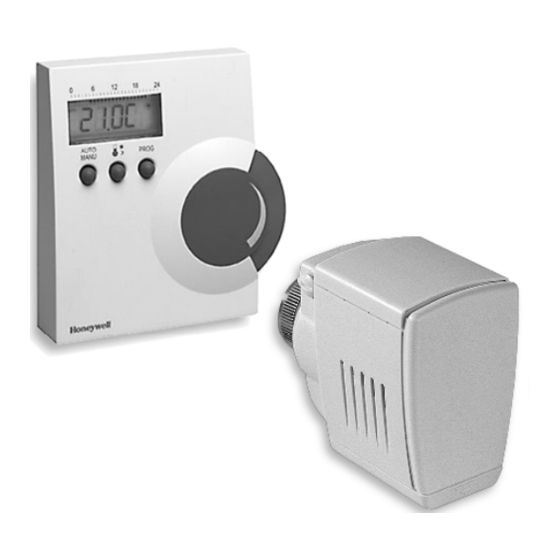
Overview Overview For Your Information Technical terms are explained in the glossary (Page 32). They are identified in the text by an *. Application The Roomtronic HR10 F controls the setpoint temperature* of a room. It consists of a drive unit and an operating unit and offers a number of comfortable functions: •... - Page 6 Overview Scope of supply 1. Operating unit 2. Connecting cable 3. Drive unit 4. Valve lantern 5. Batteries...
-
Page 7: Mounting
Mounting Mounting Selecting the mounting site When selecting the mounting site take into consideration that the ► temperature measurement is influenced if the operating unit is mounted on an outer wall or near heat sources. Mounting the drive unit Turn the radiator on before mounting. The radiator valve must be ►... - Page 8 Mounting Separate the drive unit and ► valve lantern. Mounting the valve lantern on the radiator valve Honeywell-Braukmann, MNG, Heimeier, Junkers, Landis & Gyr 'Duogyr' valves do not require an adapter. For adapters for Oventrop-, Danfoss-, Herz- and Vaillant valves please refer to Page 29.
- Page 9 Mounting Slide the valve lantern onto ► the heating valve. Slide the metal knurled nut ► onto the thread of the heat- ing valve. Tighten the metal knurled ► nut without using a tool.
- Page 10 Mounting Checking the valve lift The nose of the adjusting ring is positioned at the stop of the housing (Page 6). Turn the adjusting ring of ► the valve lantern (1) to the right until some resistance is felt. À The spindle (2) of the valve lantern is now touching the valve pin (3) of the radiator...
- Page 11 Mounting Turn the adjusting ring of ► the valve lantern (1) further to the right until the final stop is reached. radiator valve closed. With the central heating switched on, the À radiator cools down. The valve lift between the left-hand stop (open) and the right- hand stop (closed) has to amount to at least ¾...
- Page 12 Mounting Connecting the drive unit and the valve lantern To open the retainer bracket, ► turn the control knob (1) so the tip points upwards. Slide the housing onto the ► valve lantern (2). To close the retainer bracket, ► turn the control knob so the tip points sideways.
-
Page 13: Mounting The Operating Unit
Mounting Mounting the operating unit Open housing ► operating unit by pressing the concealed latching nose on the bottom (1) with a screwdriver while lifting the cover at the same time (2). Draw and drill the fastening ► holes in accordance with the drilling scheme on Page 28. - Page 14 Mounting Insert the open end of the ► cable through the recess (1) in bottom panel operating unit. Connect the cable in ac- ► cordance with the adjacent scheme. Assignment and conductor col- ors of the cables: 1 = Black 2 = Red 3 = Green 4 = Yellow...
-
Page 15: Inserting Batteries Into The Operating Unit
Mounting Inserting batteries into the operating unit The battery unit of the drive unit does not have any function. If necessary, remove any discharged batteries from the operating ► unit (please also refer to Setting the date and time, Page 14). Batteries should not be disposed of in the household garbage. -
Page 16: Setting The Date And Time
Mounting Set the date and time once automatic adaptation is complete. ► Setting the date and time The date and time must be set when first configuring the controller and after each battery change (please also refer to Page 13). Keep the button pressed for at least 2 seconds. -
Page 17: Operation
Operation Operation Display and operating elements at the operating unit 1. Display of the set heating and economy period 2. Display of the operating mode: AUTO, MANUAL or PROG button for changing between AUTO and MANUAL mode button for setting the comfort and economy temperature button for changing to programming mode... -
Page 18: Changing The Setpoint Temperature At The Adjusting Ring
Operation A rectangle symbolizes one hour of a heating period. A rectangle is displayed above a heating period of half an hour. The setpoint temperature* at the Roomtronic can be modified as follows: • Manually at the adjusting ring of the operating unit •... -
Page 19: Changing The Operating Modes
Operation Changing the operating modes The Roomtronic disposes of 3 operating modes: • Automatic mode* (AUTO) • Manual mode* (MANU) • Programming mode* (PROG) The automatic mode is the standard mode of the Roomtronic. Temperatures and heating periods are controlled by the time program. "AUTO"... -
Page 20: Automatic Functions
Operation Automatic functions Window function If you open a window so that the temperature drops strongly, the radiator controller closes the radiator valve in order to save energy. The message is then displayed in the operating unit display. When the temperature rises again the radiator controller returns to normal operation, however at the latest after 30 minutes. -
Page 21: Emergency Operation When The Batteries Are Flat
Operation Emergency operation when the batteries are flat Separate the housing of the drive unit from the valve lantern (please ► refer to Page 5). In order to open the radiator valve: Turn the blue adjusting ring at the ► valve lantern towards the plus sign. -
Page 22: Adapting
Adapting Adapting You can abort the settings carried out at any time by pressing button. The Roomtronic then returns to automatic mode. The last changes are rejected. Temperatures and control periods The Roomtronic changes between 2 setpoint temperatures ... • Comfort temperature Normal living temperature •... -
Page 23: Adapting The Comfort And Economy Temperatures
Adapting Works settings Adapting the comfort and economy temperatures Press the button. ► The current comfort temperature is displayed flashing. Turn the adjusting ring until the desired comfort temperature is ► displayed. Press the button again. ► The current economy temperature is displayed flashing. Turn the adjusting ring until the desired economy temperature is displayed. -
Page 24: Adapting The Heating And Economy Periods
Adapting Adapting the heating and economy periods You can set a first heating and economy period and, if required, a second one for each weekday. Each heating period must also have an economy period assigned to it. HINT: First adapt the heating and economy periods for all the weekdays simultaneously. - Page 25 Adapting --:-- Turn the adjusting ring until is displayed. ► Press the button. ► The new heating and economy periods are effective for all the weekdays. If you want to set a second heating and economy period: Turn the adjusting ring until the desired second heating period is ►...
- Page 26 Adapting Press the button again. ► Turn the adjusting ring until the desired first economy period is ► displayed. Press the button again. ► If you do not want to set a second heating and economy period: --:-- Turn the adjusting ring until is displayed.
-
Page 27: Adaptation At The Radiator Valve
Adapting Deleting the heating and economy periods Whenever a heating period is deleted, the corresponding economy period has to be deleted too, and vice versa. Proceed as described in the above sections on "Changing heating ► and economy periods". Turn the adjusting ring respectively to the --:-- right until is displayed. - Page 28 Adapting Activating manual adaptation The manual adaptation can be used to solve various problems: • If the radiator does not turn cold (valve does not close completely). • If the symbol is displayed (no adaptation possible). • If the symbol is displayed (valve lift too short or motor cannot be moved).
-
Page 29: Appendix
Appendix Appendix Technical data Operating range 0 °C ... +40 °C Mounting Wall mounting Max. ambient temperature / humidity 0 °C ... 50 °C / 5 % ... 90 % rel. humidity Max. storage temperature / humidity –20 °C ... +65 °C / 5 % ... 90 % rel. humidity Voltage supply 2 Mignon batteries LR 06 AA AM3... -
Page 30: Dimensions And Drilling Scheme Operating Unit
Appendix Dimensions and drilling scheme operating unit... - Page 31 Appendix Adapters for the drive unit Adapter make/type Order No. Oventrop HU 01 073341076 (knurled nut M30x1) Herz HU 02 073341725 (knurled nut M28) Danfoss adapter set 072031201 EVA 1-Danfoss RAVL (black) RAV (gray) RA (white) 072031082 Vaillant adapter EHA 1VAI Select the required adapter or change the valve lantern (Herz, ►...
- Page 32 Appendix Help with problems Problem/Display Cause Remedy Reverse disabling as Operating unit is ► described on disabled, operation is Page 19. not possible Display during the automatic adaptation, aD a Wait until the end of ► lasts approx. 2 min adaptation.
- Page 33 Appendix Motor cannot be Check the mounting. ► moved/ valve lift too Check cable ► short connection between operating unit and the drive unit. Remove the dirt from ► the radiator valve, if necessary. Carry out the manual ► adaptation scribed on Page 26.
- Page 34 Appendix Glossary Adaptation Heating period The radiator controller adapts Period in which the comfort itself to the lift of the radiator temperature is effective. valve. Manual mode Automatic mode No time program active. Set- Standard operating mode of the point adjustment via adjusting operating unit.
- Page 36 Honeywell AG Böblinger Straße 17 D – 71101 Schönaich Tel. (++49) (0) 1801 466390 www.honeywell.de This company is certificated to The right is reserved to make modifications. This document is definitive for the enclosed product and replaces all previous publications.