Table of Contents
Quick Links
Table of Contents
Troubleshooting

Related Manuals for Bosch Control 8310


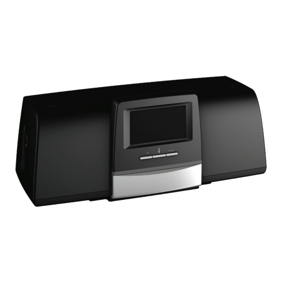
Summary of Contents for Bosch Control 8310
- Page 1 Installation and Operating Instructions Control unit Control 8310...
-
Page 2: Table Of Contents
13.4 Update of control unit software for Control 8310 ..16 Fitted modules ....... . . 7 13.4.1 Notice regarding systems containing several... -
Page 3: Explanation Of Symbols And Safety Instructions
▶ Point out the dangers of carbon monoxide (CO) and recommend the not supplied by the manufacturer. use of CO detectors. ▶ Leave the installation instructions and the operating instructions with ▶ Use only original spare parts and accessories from the manufacturer. the user for safekeeping. Control 8310 – 6720856493 (2022/07) -
Page 4: Product Information
Open Source Software This product contains proprietary software by Bosch (licensed Module according to the Bosch standard licensing conditions) and Open Source In the following, functional, central, network modules etc. are Software (licensed according to the Open Source licensing conditions). -
Page 5: Information For The User
The status of the modules, the functions and the system components Chimney sweep button (without function) installed in the control unit Control 8310 are displayed via the status Manual operation button (changed function) display LED- ( Fig 1, [10], page 5): USB connection (e.g. -
Page 6: Operation
Display of selected control unit System (Heat distribution of the selected control unit) Display of the control unit address in the networking icon. Changes to the view of the master control unit (is only displayed with slave control units). Control 8310 – 6720856493 (2022/07) -
Page 7: Troubleshooting
When using certain modules, it is advisable to mount them at specific slots ( chapter 5.2, page 8). Control 8310 – 6720856493 (2022/07) -
Page 8: Connection Of Function Modules
A power supply for 24 V components is available at slot C on the base The control unit address is set on reverse side. module. • Connection: 24 V =, max. 250 mA ▶ Do not exceed the maximum rated current. Control 8310 – 6720856493 (2022/07) -
Page 9: Standards, Regulations And Directives
For heat sources (e.g. combined heat and power unit) that are connected via, the Modbus-RTU ( Figure 7, [3], page 10): ▶ Connect communication cable to the Modbus-RTU connection. ▶ Consider connection to the heat source. Control 8310 – 6720856493 (2022/07) -
Page 10: User Interface Connections (Hmi)
Other connections may need to be established, depending on the The jumpers remain closed at the first and last BUS node. function of the modules. ▶ Observe documents and connection diagrams of the installed modules. Control 8310 – 6720856493 (2022/07) -
Page 11: Commissioning
▶ Tap on Save or Cancel. Tap on Save to apply the settings and close the assistant. If the Commissioning wizard is not run or is cancelled, the settings in the corresponding menus may be changed. Control 8310 – 6720856493 (2022/07) -
Page 12: Menu Structure
Displays the faults in the heating system. The remote control of the master control unit displays the faults of the control unit to which it is linked, or is selected via the networking. master control unit Chapter 13.6, page 16 Table 4 Main menu Control 8310 – 6720856493 (2022/07) -
Page 13: General Characteristic Data
▶ Set the modules manually. Submenu Settings/adjustment range Explanation Remark Slot 1...4 None – Slots for function modules and auxiliary modules Module configuration The installed modules can be selected from a list. Table 6 Menu Module configuration Control 8310 – 6720856493 (2022/07) -
Page 14: Connectivity
This does not depend on the control unit address that has been set. 0010010538-001 Fig. 9 Control unit connection Control unit 83xx address 0 (Master) Control unit 83xx address 1 (Slave) Control unit 83xx address 2 (Slave) Heat source Control 8310 – 6720856493 (2022/07) -
Page 15: 11.2.2 Control Unit Linking
Information on the reset main menu 11.2.2 Control unit linking Control unit Control 8310 as slave The Control unit coupling is performed in an adjustable time period. In Activation of the Control unit coupling on the control unit doing so, the master controller searches for other CBC bus participants Control 8310: on the CBC BUS. -
Page 16: Service
(accessory), or transfer data from a USB stick to the control. ▶ Call up service menu and tap Connectivity menu item. ▶ Plug USB stick into the USB connection Control 8310 ▶ With Disconnect control unit coupling, tap Activate. ( Fig 1, [9], page 5). -
Page 17: Cleaning The Control Unit
Data Protection Officer, Information Security and Privacy (C/ISP), This symbol means that the product must not be disposed Robert Bosch GmbH, Postfach 30 02 20, 70442 Stuttgart, GERMANY. of with other waste, and instead must be taken to the waste... -
Page 18: Appendix
Function test on all safety equipment carried out and documented? Have the values set been documented? E.g. data backup Operator briefed and technical documents handed over? Properly-completed commissioning confirmed. Signature/stamp/heating contractor/date Signature of service engineer Table 10 System commissioning report Control 8310 – 6720856493 (2022/07) - Page 20 Bosch Thermotechnik GmbH GB Importer: Junkersstrasse 20-24 Bosch Thermotechnology Ltd. 73249 Wernau, Germany Cotswold Way, Warndon www.bosch-thermotechnology.com Worcester WR4 9SW, United Kingdom...