ABB RELION REX640 Operation Manual
Protection and control
Hide thumbs
Also See for RELION REX640:
- Technical manual (1960 pages) ,
- Engineering manual (156 pages) ,
- Operation manual (140 pages)
Table of Contents
Quick Links
Table of Contents

Related Manuals for ABB RELION REX640


Summary of Contents for ABB RELION REX640
- Page 1 — ® RELION PROTECTION AND CONTROL REX640 Operation Manual...
- Page 3 Document ID: 1MRS759118 Issued: 2023-02-10 Revision: D © Copyright 2023 ABB. All rights reserved...
- Page 4 Copyright This document and parts thereof must not be reproduced or copied without written permission from ABB, and the contents thereof must not be imparted to a third party, nor used for any unauthorized purpose. The software or hardware described in this document is furnished under a license and may be used, copied, or disclosed only in accordance with the terms of such license.
- Page 5 Other than under explicit contractual commitments, in no event shall ABB be responsible or liable for any loss or damage resulting from the use of this manual or the application of the equipment.
- Page 6 Conformity This product complies with the directive of the Council of the European Communities on the approximation of the laws of the Member States relating to electromagnetic compatibility (EMC Directive 2014/30/EU) and concerning electrical equipment for use within specified voltage limits (Low-voltage directive 2014/35/EU).
-
Page 7: Table Of Contents
Contents Contents Introduction....................11 This manual............................. 11 Intended audience..........................11 Product documentation........................12 1.3.1 Product documentation set....................12 1.3.2 Document revision history....................12 1.3.3 Related documentation......................12 Symbols and conventions........................13 1.4.1 Symbols........................... 13 1.4.2 Document conventions......................13 Environmental aspects................14 Sustainable development........................14 Disposal of a device.......................... - Page 8 Contents Selecting local or remote use......................34 Identifying device..........................35 Changing backlight brightness and timeout...................36 Changing setting visibility........................37 Monitoring relay status........................38 4.7.1 Switchgear HMI status indications..................39 Changing language..........................41 Alarms..............................41 4.9.1 Viewing alarm list........................41 4.9.2 Acknowledging alarms......................41 4.10 Measurements and phasor diagrams....................
- Page 9 Contents 5.12 Editing values............................72 5.13 Committing settings..........................74 5.14 Clearing and acknowledging.......................76 5.15 Accessing event view..........................77 5.16 Accessing disturbance record view....................78 5.16.1 Saving disturbance records....................79 5.16.2 Triggering disturbance recorder manually..............79 5.16.3 Deleting disturbance records..................... 80 5.17 Viewing fault records..........................
- Page 10 7.5.3 Using HMI Client........................149 7.5.4 Selecting the internal fault test..................150 7.5.5 Selecting IED blocked or IED test and blocked mode..........150 ABB Product Data Registration......................151 Maintenance and Periodical Testing........... 153 Maintenance and Periodical Testing....................153 8.1.1 Maintenance......................... 153 8.1.2 Periodical Testing........................ 153 Glossary....................
-
Page 11: Introduction
1MRS759118 D Introduction Introduction This manual The operation manual contains instructions on how to operate the protection relay once it has been commissioned. The manual provides instructions for monitoring, controlling and setting the relay. The manual also describes how to identify disturbances and how to view calculated and measured power grid data to determine the cause of a fault. -
Page 12: Product Documentation
C/2020-12-10 PCL3 Content updated to correspond to the product connectivity level D/2023-02-10 PCL4 Content updated to correspond to the product connectivity level 1.3.3 Related documentation www.abb.com/ Download the latest documents from the ABB Web site mediumvoltage REX640 Operation Manual... -
Page 13: Symbols And Conventions
1MRS759118 D Introduction Symbols and conventions 1.4.1 Symbols The electrical warning icon indicates the presence of a hazard which could result in electrical shock. The warning icon indicates the presence of a hazard which could result in personal injury. The caution icon indicates important information or warning related to the concept discussed in the text. -
Page 14: Environmental Aspects
Environmental aspects 1MRS759118 D Environmental aspects Sustainable development Sustainability has been taken into account from the beginning of the product design including the pro-environmental manufacturing process, long life time, operation reliability and disposing of the device. The choice of materials and suppliers has been made according to the EU RoHS directive (2011/65/EU). -
Page 15: Rex640 Overview
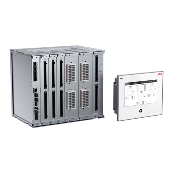
1MRS759118 D REX640 overview REX640 overview Overview REX640 is a powerful all-in-one protection and control relay for use in advanced power distribution and generation applications with unmatched flexibility available during the complete life cycle of the device – from ordering of the device, through testing and commissioning to upgrading the functionality of the modular software and hardware as application requirements change. -
Page 16: Local Hmi
REX640 overview 1MRS759118 D Figure 2: Hardware module slot overview of the REX640 relay Slot markings in enclosure (top and bottom) Ready LED The relay has a nonvolatile memory which does not need any periodical maintenance. The nonvolatile memory stores all events, recordings and logs to a memory which retains data if the relay loses its auxiliary supply. - Page 17 1MRS759118 D REX640 overview Figure 3: Example of a local HMI page The LHMI presents pages in two categories. • Operator pages are typically required as a part of an operator’s normal activities, such as a single-line diagram, controls, measurements, events or alarms •...
- Page 18 REX640 overview 1MRS759118 D State Power supply LHMI Home Alarm module Ready button acknowledged LHMI not running normally or in Steady green High frequency start-up initialization phase blinking green Process related alarm active Steady green Low frequency blinking red Process related alarm active Steady green Steady red Process related alarm has been ac-...
- Page 19 1MRS759118 D REX640 overview Table 3: Local HMI default pages Page category Pages Subpages Operator pages Overview Alarms Events Fault Records Timeline Measurements Phasors Load Profile Records Engineer pages Parameters Testing and Commissioning Force Functions Force Outputs Simulate Inputs View I/O Send Events Secondary Injection Monitoring Protection Measurement Direction...
-
Page 20: Switchgear Hmi
REX640 overview 1MRS759118 D Figure 5: Engineer pages menu Switchgear HMI The SHMI is used for setting, monitoring and controlling up to 20 REX640 protection relays and the related processes. It comprises a 7-inch color screen with capacitive touch sensing and a Home button at the bottom of the SHMI. All features of standard HMI are also available in the SHMI. - Page 21 1MRS759118 D REX640 overview Figure 6: Example of a switchgear HMI navigation page The SHMI has a navigation page which presents the physical switchgear lineup installation and indicates the status of each REX640 within the system. The area presenting a single switchgear bay has a small user-configurable bay overview section and a virtual Home button showing the status of the connected relay.
-
Page 22: Bay Overview Area
REX640 overview 1MRS759118 D Figure 7: Navigation page elements User-defined substation name User-defined name for the switchgear or sub-part of switchgear lineup controlled by the SHMI Date, time and time synchronization status Logout button and authentication status Menu button User-defined voltage level name User defined bay name and voltage level extension Bay overview area showing static or dynamic information for a bay and functioning as a navigation point to launch the HMI view for the respective... -
Page 23: Physical And Virtual Home Buttons
1MRS759118 D REX640 overview 3.4.1 Bay overview area Bay overview area consists either of a static picture or a dynamic SLD. They are configured with Graphical Display Editor in PCM600. One relay can have two overview pages. Static picture may be, for example, a drawing or a photo of switchgear lineup. Maximum size of the picture is 186 ×... -
Page 24: Hmi Communication Ports
REX640 overview 1MRS759118 D identifying which relay requires operator’s attention when the bay overview is not visible on the navigation page. When the HMI view is opened for a relay, the SHMI works exactly like a normal HMI. All the same features are available, and the Home button switches between the configured home pages and indicates the alarm status for the respective relay. -
Page 25: Web Hmi
1MRS759118 D REX640 overview Web HMI The WHMI allows secure access to the protection relay via a Web browser. The WHMI is verified with Google Chrome, Mozilla Firefox and Microsoft Edge. Figure 9: Example view of the Web HMI WHMI offers several functions. The menu tree structure on the WHMI is almost identical to the one on the LHMI. -
Page 26: Command Buttons
REX640 overview 1MRS759118 D Main groups Submenus Description Parameters Used to view the menu tree structure for the protection relay's setting parameters Language selection Used to change the language Logout Used to end the session The WHMI can be accessed locally and remotely. •... - Page 27 1MRS759118 D REX640 overview Name Description Saving values to TXT or CSV file format Freezing the values so that updates are not displayed Receiving continuous updates to the monitoring view Deleting the disturbance record(s) Saving the disturbance record files Viewing all fault records Clearing all fault records Importing settings Exporting settings...
-
Page 28: User Authorization
REX640 overview 1MRS759118 D User authorization The user management for the protection relay can be handled in two possible ways. Only one user management way can be enabled in the protection relay at a time. For more information, see the cyber security deployment guideline. Local user account management Four factory default user accounts (VIEWER, OPERATOR, ENGINEER and ADMINISTRATOR) have been predefined for the LHMI and the WHMI, each with... -
Page 29: Station Communication
1MRS759118 D REX640 overview Station communication Operational information and controls are available through a wide range of communication protocols including IEC 61850 Edition 2, IEC 61850-9-2 LE, IEC ® 60870-5-103, IEC 60870-5-104, Modbus and DNP3. Full communication capabilities, for example, horizontal communication between the relays, are only enabled by IEC 61850. -
Page 30: Pcm600 And Relay Connectivity Package Version
If it is needed to use the possibilities provided by the Modification Sales concept, please contact your local ABB unit. REX640 Operation Manual... -
Page 31: Using Hmi
1MRS759118 D Using HMI Using HMI Logging in Once the HMI is connected to the relay, tap the LOGIN icon on the menu bar. Figure 10: Logging in to local HMI Acknowledge the login banner notification if displayed. Figure 11: Login banner in local HMI User Editable login banner provides a way to display a definitive warning to any possible intruders that may want to access your system that certain types of activity are illegal, but at the same... - Page 32 Using HMI 1MRS759118 D Provide the username and password in the dialog box. Keep the SHIFT key pressed for two seconds to switch from typing in lowercase to typing in uppercase, and vice versa. Figure 12: Providing the user credentials The user is logged in to the protection relay and the username is displayed on the menu bar of the HMI.
-
Page 33: Managing Forgotten Password
HMI port's IP address is used in this instruction, check e.g. from PCM600 project if it has been changed.) Forward the displayed OTP related information to ABB's technical customer support to receive a one-time password. Reset the ADMINISTRATOR password. -
Page 34: Selecting Local Or Remote Use
Using HMI 1MRS759118 D Tap Log out. Figure 15: Logging out Logging out from the SHMI automatically results in a logout from all of the connected relays. Changing the password causes an immediate logout. Changing password is not available in the logout menu when the navigation page is open. -
Page 35: Identifying Device
1MRS759118 D Using HMI Select Off, Local or Remote. By setting Station authority parameter, more choices such as L+R and L+S+R will become available. In local position, the primary equipment, such as circuit breakers or disconnectors, can be con-trolled via the LHMI or SHMI when connected to a selected relay. -
Page 36: Changing Backlight Brightness And Timeout
Using HMI 1MRS759118 D Tap HW modules and select Detached LHMI to check the information of the LHMI. Figure 17: Identifying device Changing backlight brightness and timeout Tap the menu button. Tap Parameters. Tap Configuration and then HMI. Tap Edit. Tap Backlight brightness value field. -
Page 37: Changing Setting Visibility
1MRS759118 D Using HMI Give the new value and tap OK. Figure 18: Changing backlight brightness Changing setting visibility Tap the menu button. Tap Parameters. Tap Settings from the left and select a function. REX640 Operation Manual... -
Page 38: Monitoring Relay Status
Using HMI 1MRS759118 D Tap Advanced or Basic on the upper right corner of the page. Figure 19: Changing setting visibility Monitoring relay status Tap the menu button. Tap Relay Status. In case of active internal fault or warning, tap More Information. REX640 Operation Manual... - Page 39 1MRS759118 D Using HMI Tap Monitoring to open the monitoring menu. Figure 20: Selecting self-supervision REX640 Operation Manual...
-
Page 40: Switchgear Hmi Status Indications
Using HMI 1MRS759118 D 4.7.1 Switchgear HMI status indications In the panel lineup overview, a green square indicates a healthy state and a red triangle the states that require operator’s attention. Table 6: Status icons Status icon Description Normal relay status The relay has alarms or some other state that requires oper- ator’s attention. -
Page 41: Changing Language
1MRS759118 D Using HMI Status Priority Home button Overview Acknowled Relay under normal Steady green operation and con- nected to the SHMI Changing language Tap the menu button. Tap Language on the lower right corner of the page. Select a language from the list. Alarms 4.9.1 Viewing alarm list... - Page 42 Using HMI 1MRS759118 D Lockout or latched trip can also be reset on this page by tapping Reset Trip. When a persisting alarm is acknowledged, it does not disappear from the list until the cause of the alarm is resolved. Figure 21: Acknowledging alarms REX640 Operation Manual...
-
Page 43: Measurements And Phasor Diagrams
1MRS759118 D Using HMI 4.10 Measurements and phasor diagrams 4.10.1 Viewing measurements The Measurements page is usually one of the Operator pages. Swipe the LHMI screen until the Measurement page is shown. The number of measurements on the Measurement page depends on the LHMI configuration made with GDE. -
Page 44: Showing Parameters
Using HMI 1MRS759118 D If more than one phasor diagram page are available, select one from the list opened. Figure 23: Phasors page 4.11 Showing parameters Tap the menu button. Tap Parameters. REX640 Operation Manual... -
Page 45: Viewing Protection Characteristics
1MRS759118 D Using HMI Tap Settings from the left and select a function. Figure 24: Showing parameters 4.11.1 Viewing Protection Characteristics Navigate to Parameters > Settings. Select protection function to enter to parameter page. Tap Characteristics button to show function characteristics. Tap Characteristics button to return to parameter page. -
Page 46: Editing Values
Using HMI 1MRS759118 D 4.12 Editing values Tap Edit on the lower left corner of the page to activate the edit mode. A blinking icon on the menu bar indicates that the edit mode is active. Enter a value and tap OK. Figure 26: Entering a numeric value Figure 27: Entering an alphanumeric value REX640... -
Page 47: Committing Settings
1MRS759118 D Using HMI 4.13 Committing settings The blinking icon on the menu bar indicates that at least one parameter value has been changed and storing to the nonvolatile memory is required. Tap the icon or Edit button. REX640 Operation Manual... - Page 48 Using HMI 1MRS759118 D Tap Store, Reject or Cancel in the dialog box that opens. Tapping Reject exits the edit mode without storing the values to the nonvolatile memory. Tapping Cancel closes the dialog box and returns to parameter editing. Figure 28: Storing required indication on the menu bar Figure 29: Storing or rejecting parameter changes REX640...
-
Page 49: Clearing And Acknowledging
1MRS759118 D Using HMI 4.14 Clearing and acknowledging Tap the menu button. Tap Clear. Select the items to be cleared or acknowledged by tapping the corresponding rows. Swipe the list vertically to scroll up and down. Tap Clear from Relay to clear or acknowledge the selected items. Figure 30: Clearing and acknowledging 4.15 Accessing disturbance records... -
Page 50: Viewing Fault Records
Using HMI 1MRS759118 D Tap Save to USB to save the selected records to the USB memory. Save to USB is not activated until a USB memory is connected to the USB port of the HMI. Figure 31: Selecting disturbance records Tap Trigger Recording to manually trigger a recording. -
Page 51: Selecting Usb Actions
1MRS759118 D Using HMI Tap the time stamp in the list to see the data of the record. Both the fault records list and the data window can be scrolled up and down by swiping vertically the corresponding section of the page. Figure 32: Fault records page 4.17 Selecting USB actions... -
Page 52: Using Local Hmi Help
Using HMI 1MRS759118 D Tap Save to USB. The USB port of the LHMI is disabled by default. To be able to access the USB actions page, the USB port needs to be enabled by the Enable USB access via Parameters > Configuration > HMI. parameter Save to USB is not activated until a USB memory is connected to the USB port of the HMI. -
Page 53: Changing Setting Group
1MRS759118 D Using HMI The edit mode needs to be activated to see the buttons on the Parameters and Monitoring pages. Figure 34: Page help and parameter help buttons 4.19 Changing setting group Tap the menu button. Tap Parameters. Setting group list is opened by default. Tap Edit. -
Page 54: Controlling
Using HMI 1MRS759118 D Tap Store. Figure 35: Selecting active setting group 4.20 Controlling Controllable objects, such as circuit breakers, disconnectors and earthing switches, can be opened and closed via the single-line diagram. Tap the object in the single-line diagram to select it. REX640 Operation Manual... - Page 55 1MRS759118 D Using HMI to open or to close the selected object. Figure 36: Selecting object (circuit breaker) and control buttons An interlocked object is indicated by the padlock symbol in the single-line diagram. Breaker operation in Configuration > Control > HMI is set to If the parameter "After confirmation", a confirmation dialog box opens after tapping the control Select...
- Page 56 Using HMI 1MRS759118 D Figure 37: Confirming object closing Control operations cannot be executed from the SHMI navigation page. Navigate to the HMI view to perform control operations. Close delay mode in Configuration > Control > LHMI is set If the parameter to "In use", a timer is started after tapping the close button and accepting the possible confirmation dialog.
-
Page 57: Bookmarking
1MRS759118 D Using HMI Figure 38: Closing circuit breaker with a delay 4.21 Bookmarking pages A bookmark can be created to any page on the LHMI. Maximum six bookmarks can be created. Navigate to the page to be bookmarked. Touch the Home button for one second to open the Bookmarks page. Tap any Bookmark the active page icon to store the bookmark for the selected page. - Page 58 Using HMI 1MRS759118 D Figure 39: Bookmarking pages REX640 Operation Manual...
-
Page 59: Using Web Hmi
1MRS759118 D Using Web HMI Using Web HMI Connecting to Web HMI Connection to WHMI can be established using different communication card ports or the LHMI service port. WHMI is disabled by default and can be enabled with a setting parameter. As only secure communication is supported for the WHMI, it must be accessed from a Web browser using the HTTPS protocol. - Page 60 Using Web HMI 1MRS759118 D Acknowledge the login banner notification if displayed. Figure 40: Login banner in WebHMI User Editable login banner provides a way to display a definitive warning to any possible intruders that may want to access your system that certain types of activity are illegal, but at the same time, it also advises the authorized and legitimate users of their obligations relating to acceptable use of the computerized...
- Page 61 1MRS759118 D Using Web HMI Type the password. Figure 41: Entering username and password to use the Web HMI If logging in fails because all sessions are used, an error message is shown on the login page. Figure 42: Web HMI error message REX640 Operation Manual...
-
Page 62: Logging Out
Using Web HMI 1MRS759118 D Select the role if an additional view opens. This view opens if there are several user roles configured. Figure 43: Selecting user role The progress indicator is displayed until the WHMI opens and the dashboard view is shown. -
Page 63: Identifying Device
1MRS759118 D Using Web HMI Identifying device The Information menu includes detailed information about the device, for example, revision and serial number. Select Device on the menu bar. Select Information. Click a submenu to see the data. Figure 44: Viewing device information Viewing dashboard The Dashboard view is active automatically after logging in to WHMI and provides an overview of the protection relay including, for example, the device status,... -
Page 64: Changing Language
Using Web HMI 1MRS759118 D Select Self-Supervision. The Self-Supervision view shows currently active internal faults and warnings. Figure 46: Self-supervision: one internal fault is currently active Changing language The active language of the Web server session is indicated in the caption of the menu bar button. - Page 65 1MRS759118 D Using Web HMI The Persisting Alarms view lists the active alarms. b) The Fleeting Alarms view shows the alarms that are not active anymore but are not acknowledged. The Available Alarms view contains all configured alarms. Acknowledged alarms are indicated using icon Priority alarms are indicated with icon Figure 48: Viewing persisting alarms...
-
Page 66: Acknowledging Alarms
Using Web HMI 1MRS759118 D 5.7.2 Acknowledging alarms Select Recordings on the menu bar. Select Alarm List. Select the alarm view. Select the alarms using check boxes. Click Acknowledge. Figure 51: Acknowledging alarms Alarm list items can be configured in HMI Event Filtering in PCM600. REX640 Operation Manual... -
Page 67: Measurements And Phasor Diagrams
1MRS759118 D Using Web HMI Measurements and phasor diagrams 5.8.1 Viewing measurements Select Measurements on the menu bar. Select Measurements from the drop-down list. Figure 52: Viewing measurements Measurements are also displayed in the Dashboard view. 5.8.2 Viewing phasor diagrams Select Measurements on the menu bar. - Page 68 Using Web HMI 1MRS759118 D Select the phasor from the drop-down list on the Phasor Diagrams page to view Figure 54: Selecting the phasor Select Custom from the drop-down list on the Phasor Diagrams page to open the dialog with the phasor list. Figure 55: Selecting the custom phasors REX640 Operation Manual...
-
Page 69: Viewing Monitoring
1MRS759118 D Using Web HMI In the Custom dialog, select the phasors to be monitored and click Close. Figure 56: Editing custom phasor list Click the Select reference button to select a reference phasor and then click Close. Figure 57: Selecting the reference phasor WHMI measurements and phasor diagrams follow LHMI definitions and can be edited with Graphical Display Editor in PCM600. -
Page 70: Viewing Single-Line Diagram
Using Web HMI 1MRS759118 D Select the monitored view from the left navigation bar. Figure 58: Monitoring data 5.10 Viewing single-line diagram The single-line diagram is displayed on the dashboard and the Single Line Diagram page. If there are more than one page, the first page is displayed and the others are included in the drop-down list. -
Page 71: Showing Parameters
1MRS759118 D Using Web HMI 5.11 Showing parameters Some function blocks have a function-specific ON/OFF setting. When the function setting is "off", all settings are hidden and when the function setting is "on", all settings are visible based on the other visibility and hiding rules. Operation parameter under the Switch a function block on or off via the function block. -
Page 72: Editing Values
Using Web HMI 1MRS759118 D Figure 61: Enabling settings The Parameter List page offers filtering functionality where only chosen parameters are displayed, saved or printed. There are various options for filtering. Enabled Settings hides settings of disabled function blocks. This option is checked by default. - Page 73 1MRS759118 D Using Web HMI Click Enable Edit. If the edit mode is enabled accidentally, click Disable Edit. Editing cannot be disabled when a value has already been written to the protection relay. After clicking Write to Relay, click either Reject Changes or Store Changes.
- Page 74 Using Web HMI 1MRS759118 D Edit the value. The minimum, maximum and step values for a parameter are shown in the MIN., MAX. and STEP columns. Figure 63: Editing a value If the entered value is within the accepted value range, the selection is highlighted in blue.
-
Page 75: Committing Settings
1MRS759118 D Using Web HMI 5.13 Committing settings Editable values are stored either in RAM or a nonvolatile flash memory. The values stored in the flash memory are in effect also after a reboot. Some parameters have an edit-copy. If writing is cancelled, the values with an edit- copy are immediately restored to the original value. -
Page 76: Clearing And Acknowledging
Using Web HMI 1MRS759118 D Click Store Changes to store the values to the flash memory. Click Reject Changes to cancel saving settings. If the parameter has an edit-copy, the original parameter value is restored. If the parameter does not have an edit-copy, the edited parameter value remains visible until the protection relay is rebooted. -
Page 77: Accessing Event View
1MRS759118 D Using Web HMI Select the item to be cleared. Click Clear from Relay. Figure 69: Clearing indications and LEDs 5.15 Accessing event view The event view contains a list of events produced by the application configuration. When the event page is opened, it displays up to 20 latest events at one time. The event list is updated automatically. -
Page 78: Accessing Disturbance Record View
Using Web HMI 1MRS759118 D Select a page to view older events. Figure 71: Viewing events To save the events as .txt or .csv files, click Export and select the file format from the drop-down list. The CSV file can be opened with a spreadsheet program such as OpenOffice.org Calc or Microsoft Excel. -
Page 79: Saving Disturbance Records
1MRS759118 D Using Web HMI 5.16.1 Saving disturbance records Select Recordings on the menu bar. Select Disturbance Records from the drop-down list. To save the disturbance record files, click the Export button in the Export Files column of the record. Both disturbance record files CFG and DAT are saved at once. -
Page 80: Deleting Disturbance Records
Using Web HMI 1MRS759118 D Click Trigger RecordingTrigger Recording. Figure 75: Triggering recording Figure 76: Triggering recording - progress bar 5.16.3 Deleting disturbance records Select Recordings on the menu bar. Select Disturbance Records from the drop-down list. Delete records in one of the alternative ways. Select all and click Delete to delete all records. -
Page 81: Viewing Fault Records
1MRS759118 D Using Web HMI 5.17 Viewing fault records Select Recordings on the menu bar. Select Fault Records from the drop-down list to view a list of all available fault records. Click a record from the Fault records list to open the fault record details view. To go back to the list view, click View All. -
Page 82: Exporting Load Profile Records
Using Web HMI 1MRS759118 D 5.18 Exporting load profile records Select Recordings on the menu bar. Select Load Profile Record from the drop-down list. To export the load profile record files, click the Export button in the Export Files column. Both load profile record files CFG and DAT are saved at once. Save the CFG and DAT files in the same folder on the computer. -
Page 83: Importing Settings
1MRS759118 D Using Web HMI 5.19.2 Importing settings The parameter export and import function can be used, for example, when the protection relay's parameters are set using the WHMI instead of PCM600. The protection relay's settings engineered with PCM600 can be exported to XRIO files and imported to the WHMI. -
Page 84: Exporting Report Summary
Using Web HMI 1MRS759118 D Click Import Settings. Wait until the file transfer is complete. Figure 82: Importing settings Click Store to commit the imported settings to the relay. Wait until the import is complete. Click Cancel to cancel the import. Both the WHMI and the relay revert to the settings in use prior to the import. -
Page 85: Using Web Hmi Help
1MRS759118 D Using Web HMI Click Export to export the .zip file with the selected files. Figure 85: Report Summary page 5.21 Using Web HMI help The context-sensitive WHMI help provides information on a single parameter, for example. • Move the mouse over the to display the help dialog box. -
Page 86: Troubleshooting
Inspect the protection relay visually. • Inspect the protection relay visually to find any physical error causes. • If you can find some obvious physical damage, contact ABB for repair or replacement actions. Check whether the error is external or internal. -
Page 87: Reading Of Internal Log Files
Wait for the confirmation that the file is saved to the USB folder, tap OK, and tap Safely Remove USB. Locate the .zip file saved to the HMI folder of your USB stick and send it to ABB customer service for further analysis. -
Page 88: Checking Local Hmi Connectivity
Troubleshooting 1MRS759118 D WHMI is disabled by default. It can be enabled by the HMI mode parameter via Configuration > HMI. Reboot the relay for the change to take effect. 6.1.5 Checking local HMI connectivity If the connection between the LHMI and the relay is lost, check the following. Check that the RJ-45 cable is properly connected between the LHMI's main unit port X1.1. -
Page 89: Self-Supervision
1MRS759118 D Troubleshooting Self-supervision The protection relay's extensive self-supervision system continuously supervises the relay’s software, hardware and certain external circuits. It handles the run-time fault situation and informs the user about a fault via the LHMI, the relay's main unit power module Ready LED and through the communication channels. -
Page 90: Internal Faults
Troubleshooting 1MRS759118 D Figure 88: Relay self-supervision status on Web HMI In addition, the last boot reason and time are shown on both LHMI and WHMI. 6.2.1 Internal faults When an internal relay fault is detected, the relay protection operation is disabled, the self-supervision output relay is de-energized, and the change-over contact is released. - Page 91 Figure 89: Output contact The internal fault code indicates the type of internal relay fault. When a fault appears, the code must be recorded so that it can be reported to ABB customer service. More details about the active internal fault are found on the Relay Status page.
- Page 92 Start up error: If relay SW has just been System error HW/SW mismatch updated, redo it. If not re- covered, contact your near- est ABB representative to check the next possible corrective action. Internal Fault Start up or runtime Yes (3) Restart the relay.
- Page 93 Internal Fault Start up error: Do factory restore. If not System error Missing order num- recovered, contact your nearest ABB representative to check the next possible corrective action. Internal Fault Start up error: Yes (3) Restart the relay. If recov-...
- Page 94 Troubleshooting 1MRS759118 D Slow 10min self- recovery Fast self- Fault Immediate Additional recovery (# of Action in permanent fault Fault indication code information attempt attempts) IRF-mode state code 10: Watchdog reset Internal Fault Start up error: EE- Restart the relay. If recov- LHMI module PROM error in LHMI ered by restarting, contin-...
- Page 95 1MRS759118 D Troubleshooting Slow 10min self- recovery Fast self- Fault Immediate Additional recovery (# of Action in permanent fault Fault indication code information attempt attempts) IRF-mode state Internal Fault Runtime error: Er- Yes (3) Restart the relay. If recov- COM card error ror in the COM ered by restarting, contin- card.
- Page 96 Troubleshooting 1MRS759118 D Slow 10min self- recovery Fast self- Fault Immediate Additional recovery (# of Action in permanent fault Fault indication code information attempt attempts) IRF-mode state Internal Fault Runtime error: Yes (3) Check wirings. Restart the PO-relay(s), Slot Faulty Power Out- relay.
- Page 97 1MRS759118 D Troubleshooting Slow 10min self- recovery Fast self- Fault Immediate Additional recovery (# of Action in permanent fault Fault indication code information attempt attempts) IRF-mode state change the hardware mod- ule in slot C. Internal Fault Start up error: Card Check that the card in slot Conf.
- Page 98 Product license er- cation Sales has been car- cense error ror, license file is ried out, redo the update. If not found or is not recovered, contact your wrong nearest ABB representative to check the next possible corrective action. REX640 Operation Manual...
-
Page 99: Warnings
LHMI Home button flashes red. If a warning appears, record the name and code so that it can be provided to ABB customer service. See the operation manual for more information on reading internal log files from the relay. On the LHMI, an active warning is indicated with a yellow LED. More information about the warning and recovery options can be accessed by tapping More Information. - Page 100 Troubleshooting 1MRS759118 D Figure 94: More information about the warning The warning alarm is only displayed when configured in PCM600 event filtering. Table 10: Warning indications and codes Warning indication Warning code Additional information Watchdog reset A watchdog reset has occurred. Power down det.
-
Page 101: Power Supply Module Ready Led And Hmi Home Button Led
1MRS759118 D Troubleshooting Warning indication Warning code Additional information Comm. channel down Redundant Ethernet (HSR/ PRP) communication interrupted. Settings mismatch Mismatch between parameter set- tings and application configuration. Protection comm. Error in protection communication. ARC1 cont. light A continuous light has been detec- ted on the ARC light input 1. - Page 102 Troubleshooting 1MRS759118 D State Power supply LHMI Home Alarm module Ready button acknowledged Process related alarm has been ac- Steady green Steady green tive earlier, but is not any more ac- tive Relay set to Test Mode LF blinking green LF blinking green No The physical SHMI Home button has two operation modes.
-
Page 103: Correction Procedures
1MRS759118 D Troubleshooting Correction procedures 6.3.1 Creating relay backup in HMI • Pair the HMI and the relay to activate the automatic backup. The relay backup is read and stored by the LHMI when any change in relay configuration files (see Table 12 for details) or settings has occurred and 24 hours has elapsed from the last change. -
Page 104: Rebooting The Software
Troubleshooting 1MRS759118 D When the relay is in IRF error (the Home button flashes red fast), the backup is not made. The relay's device certificate and the CA root certificate are not part of the backup. If PKI has been configured, this must be reconfigured using the corresponding tools. - Page 105 1MRS759118 D Troubleshooting In the Pair Panel & Relay dialog box, tap Pair. Figure 95: Panel not paired with the relay The Restore Configuration dialog box automatically opens if the LHMI has a compatible backup available. Figure 96: Restoring saved configuration REX640 Operation Manual...
- Page 106 Troubleshooting 1MRS759118 D Tap Details to see the differences in product and system identifiers between the backup and the new relay. Figure 97: Viewing the details of the backup and the new relay LHMI restores the relay backup if the relay's serial number is different from that in the backup and the composition code of the relay contains all the options in the backup.
- Page 107 1MRS759118 D Troubleshooting Tap Write Configuration to Relay. The relay boots so that the new configuration can be taken into use. Figure 98: Relay rebooting The following dialog box appears when the relay backup is restored. Figure 99: Backup restoring succeeds If errors occur, the error details are shown.
-
Page 108: Restoring Relay Backup From Switchgear Hmi
Troubleshooting 1MRS759118 D Figure 100: Backup restoring fails 6.3.5 Restoring relay backup from switchgear HMI This chapter describes how configuration backup is restored from SHMI. As a precondition for restoring a backup from the SHMI, the replacement relay’s license must include the same or wider capabilities than the faulty relay’s license. The replacement relay must have the same HW modules in the same slots as the faulty relay although the other HW modules may differ. -
Page 109: Setting Passwords
In IED Users or on the LHMI, change the password of the user account. Log in as administrator to reset the users' passwords. For more information on user management, see the cyber security deployment guideline. If the administrator password is lost, contact ABB's technical customer support to retrieve the administrator level access. 6.3.7 Identifying relay application problems •... - Page 110 Troubleshooting 1MRS759118 D In case of persistent faults originating from protection relay's internal faults, contact ABB for repair or replacement actions. REX640 Operation Manual...
-
Page 111: Commissioning
1MRS759118 D Commissioning Commissioning Commissioning checklist Familiarize yourself with the protection relay and its functionality before you start the commissioning work. • Ensure that you have all the needed station drawings such as single line and wiring diagrams. • Ensure that your version of the technical manual applies to the protection relay version you test. -
Page 112: Checking Ct Circuits
Commissioning 1MRS759118 D The polarity must be correct before connecting auxiliary power supply. 7.2.2 Checking CT circuits Check that the wiring is in strict accordance with the supplied connection diagram. The CTs must be connected in accordance with the connection diagram of the project, both with regards to phases and polarity. -
Page 113: Checking Binary Input And Output Circuits
1MRS759118 D Commissioning • Polarity check • VT circuit voltage measurement (primary injection test) • Earthing check • Phase relationship • Insulation resistance check The polarity check verifies the integrity of circuits and the phase relationships. The polarity must be measured as close to the protection relay as possible. The primary injection test verifies the VT ratio and the wiring all the way from the primary system to the protection relay. - Page 114 For user authorization for PCM600, see the PCM600 documentation. Policy change and configuration is not allowed when the protection relay is in offline mode in PCM600. If the last ADMINISTRATOR password is lost, contact ABB's technical customer support to retrieve the administrator level access. REX640...
-
Page 115: Setting Protection Relay And Communication
1MRS759118 D Commissioning Setting protection relay and communication 7.4.1 Setting the communication between protection relays and PCM600 The communication between the protection relay and PCM600 is independent of the used communication protocol within the substation or to the NCC. It can be seen as a second channel for communication. -
Page 116: Communication Settings
Commissioning 1MRS759118 D Technical keys of the IEDs in the PCM600 project are configured to match the technical keys of the physical IEDs. For successful protection relay engineering and usage, the workstation firewall TCP and UDP port configurations should be checked, especially for IEC 61850 and FTP. - Page 117 1MRS759118 D Commissioning Table 15: Secondary IP address parameters Parameter Options Description Configuration/Communica- False (default) Network 2 disabled tion/Ethernet/Network 2 ad- dress/ Enable TRUE Network 2 enabled Configuration/Communica- 0.0.0.0 IP address for Network 2 tion/Ethernet/Network 2 ad- dress/IP address Configuration/Communica- 0.0.0.0 Subnet address for Network 2 tion/Ethernet/Network 2 ad-...
- Page 118 Commissioning 1MRS759118 D ARC1001 COM1001 COM1002 COM1003 Figure 101: Ethernet modes with Network 1 and Network 2 Network 1 Network 1/Network 2 7.4.2.2 Protocol control It is possible to allow or block different protocols for different network interfaces in the protection relay using the parameters in Configuration > Communication > Protocols >...
- Page 119 1MRS759118 D Commissioning Table 16: Protocol control in the protection relay Parameter Options Description Configuration/Commu- Denies FTP and FTPS nication/Protocols/Net- Allows FTP and FTPS work1/FTP Secure (Default) Allows FTPS only Configuration/Commu- Denies FTP and FTPS nication/Protocols/Net- Allows FTP and FTPS work2/FTP Secure (Default) Allows FTPS only...
- Page 120 Commissioning 1MRS759118 D the FTP and IEC 61850 MMS write access on Network 1 and 2 prevents the user from updating the configuration to the protection relay from PCM600. Disabling the HTTPS write access prevents the user from writing setting changes from WHMI. Table 17: Protocol write access in the protection relay Parameter Options...
- Page 121 1MRS759118 D Commissioning 7.4.2.4 Physical locations of the serial channels The physical location of the COM1 and COM2 drivers depends on the link mode used which, in turn, depends on the used communication hardware option. Serial channels can be found on communication boards COM1004...COM1005. •...
- Page 122 Commissioning 1MRS759118 D Table 19: LED configuration (COM1004...COM1005) Description X1 LANA X2 LANB X6 LD X7 TX FO-UART X8 TX RS-485/COM2 X8 TX RS-485/COM1 IRIG-B IRIG-B 7.4.2.5 Assigning of a serial communication protocol to a COM serial port The settings of the serial communication protocol instance include a setting Port or Serial port , which is used to select the COM1 or parameter, called either COM2 setting.
- Page 123 1MRS759118 D Commissioning Counters Description ple, Modbus RTU) or on special start and stop characters (for example, Modbus ASCII). Frames discarded Counts all protocol-specific erroneous frames received. If the driver detects an error while receiving a frame, the whole frame is automatically discarded. This also means that the protocol in question never receives a faulty link frame from the driver.
-
Page 124
Commissioning 1MRS759118 D 7.4.2.9 Setting communication protocol parameters Select Main menu > Configuration > Communication >
. Change the protocol specific settings. Possible settings to be changed are, for example, the selected communication port, address and link mode. REX640 Operation Manual... - Page 125 1MRS759118 D Commissioning 7.4.2.10 RS-485 bias and termination settings A 6 x DIP switch is located on the COM1004...COM1005 cards. The COM card needs Figure 103 to be pulled out from the relay case to access the switch. See the location of the switch. RS-485 biasing and termination settings are possible through this switch.
-
Page 126: Connecting And Setting Hmi
Commissioning 1MRS759118 D 7.4.3 Connecting and setting HMI • Connect the LHMI to the relay either directly from the main unit port X1.1 to the relay’s X0/HMI port or through station network from the main unit port X1.1 to the relay’s Network 1 port. The HMI’s service port X1.2 is intended for local service access to the relay using PCM600 or the WHMI. - Page 127 1MRS759118 D Commissioning Table 24: Example of communication settings for direct local HMI connec- tion Parameter Value HMI communication pa- Main Unit Port/Automatic Address Checked rameter Main Unit Port/Address Main Unit Port/Netmask Main Unit Port/Gateway Not checked Main Unit Port/Gateway Address Service Port/Address 192.168.1.1 Service Port/Netmask...
- Page 128 Commissioning 1MRS759118 D 7.4.3.2 Connecting local HMI to a relay through station network PCM600 or WHMI can be used to read the network settings of the relay's station port via Configuration > Communication > Ethernet > Network1 address. On the LHMI, tap Network Settings to configure the network settings of the main unit port X1.1.
- Page 129 1MRS759118 D Commissioning On the Network Settings page, clear the Automatic Address check box and edit the network settings of the LHMI's main unit port. Address and Netmask settings should match the relay settings found in Configuration > Communication > Ethernet > Network1 address. Enter the IP address for the LHMI’s main unit port, not the relay’s station port.
- Page 130 Commissioning 1MRS759118 D In the Relay address dialog box, type the relay's address found in Configuration > Communication > Ethernet > Network1 address and tap OK. The LHMI connects to the relay through the station port. Figure 107: Typing the relay IP address Table 25: Example of communication settings for the local HMI connection through station network Parameter...
- Page 131 1MRS759118 D Commissioning LHMI LHMI LHMI LHMI LHMI LHMI Switch REX640 1 REX640 1 REX640 2 REX640 2 REX640 3 REX640 3 REX640 2 REX640 3 REX640 1 Figure 108: Example of local HMI connection through station network 7.4.3.3 Connecting switchgear HMI to a relay through station network This chapter describes connection and next chapter pairing process.
- Page 132 Commissioning 1MRS759118 D On the Network Settings page, clear the Automatic Address check box and edit the network settings of the LHMI's main unit port. Address and Netmask settings should match the relay settings found in Configuration > Communication > Ethernet > Network1 address. Enter the IP address for the LHMI’s main unit port, not the relay’s station port.
- Page 133 1MRS759118 D Commissioning In the Relay address dialog box, type the IP address of one of the relays that belongs to the switchgear HMI configuration and tap OK. The relay's address can be found in Configuration > Communication > Ethernet > Network1 address. The SHMI connects to the relay through the station port and automatically fetches information for the rest of the relays.
- Page 134 Commissioning 1MRS759118 D Parameter Value REX640 communication Configuration/Communication/ 192.168.2.10 parameters Ethernet/Network1/IP address Configuration/Communication/ 255.255.255.0 Ethernet/Network1/Subnet mask Service PC network IP address Obtain automatically adapter for HMI service port SHMI SHMI Switch REX640 1 REX640 1 REX640 2 REX640 2 REX640 3 REX640 3 REX640 2 REX640 3...
- Page 135 1MRS759118 D Commissioning In the confirmation window, tap Trust this Relay. Figure 113: Confirming the relay connection A page for initiating the pairing opens. To initiate pairing, login as administrator. Figure 114: Administrator login required Finalize the pairing process depending on the HMI used. To pair the LHMI with one relay only, tap Pair.
- Page 136 Commissioning 1MRS759118 D Figure 115: Pairing the local HMI with the relay Figure 116: Pairing the switchgear HMI with the relays After successful pairing, the LHMI Home page opens. If Pair is selected while connecting to the first relay in a switchgear, the SHMI attempts to pair with all the relays it finds and is able to connect and login to within the switchgear.
- Page 137 1MRS759118 D Commissioning 7.4.3.5 Setting system time and time synchronization • Select Configuration > Time > System time to set the system time and time zone. • Select Configuration > Time > Synchronization > Synch source to set the synchronization source. Setting daylight saving time The protection relay can be set to determine the correct date for the DST shift every year.
-
Page 138: Testing Of Protection Relay Operation
Commissioning 1MRS759118 D Testing of protection relay operation The protection relay has to be in the test mode before the digital outputs and certain output signals of protection and other functions can be activated. 7.5.1 Selecting IED test mode The test mode can be activated using the LHMI. The Home button is flashing green at low frequency to indicate that the test mode is activated. - Page 139 1MRS759118 D Commissioning visualized format on the Testing and Commissioning pages found on the top bar menu. HMI client can be opened from PCM600. Some of the Testing and Commissioning pages require the relay to be set in test mode. Figure 118: Home page for Testing and Commissioning pages 7.5.2.1 Testingl I/O interface...
- Page 140 Commissioning 1MRS759118 D Tap the module on the page to open the module-specific page. to scroll over the different modules. Figure 119: View I/O page On the Force Outputs page, force the state of digital outputs. Figure 120: Force Outputs page REX640 Operation Manual...
- Page 141 1MRS759118 D Commissioning Tap the module on the page to open the module-specific page. to scroll over the different modules. On the module-specific page, select state On or Off for the selected output channel and tap Force. Figure 121: Forcing outputs of selected module On the Simulate Inputs page, simulate the digital and analog inputs.
- Page 142 Commissioning 1MRS759118 D On the BIO module specific page, select On or Off for the selected channel and tap Simulate. d) On the AIM/SIM module specific page, select Primary or Secondary for Simulation Unit, set the simulation signal value for a channel and tap Simulate.
- Page 143 1MRS759118 D Commissioning All current and voltage input signals (channels) share the same phase angle value, that is, they are in phase. 7.5.2.2 Testing functions On the Force Functions page, activate or deactivate an output signal for protection or other function in one of the alternative ways. Tap Edit, select the protection category from the left of the page and activate or deactivate an output signal of a function from the list.
- Page 144 Commissioning 1MRS759118 D On the Send Events page, send a selected event over the station bus to a substation client. The sent events are defined in the IEC 61850 data sets. To send all available events in the relay, tap Send All Events. When the events are sent, the related functions are not activated.
- Page 145 1MRS759118 D Commissioning 7.5.2.3 Checking GOOSE data On the GOOSE Receiving page, check the GOOSE data that the relay subscribes from the Ethernet network. The left side of this page shows a list of devices that send GOOSE messages to the relay. These devices that publish data for the relay are defined in the relay configuration.
- Page 146 Commissioning 1MRS759118 D On the GOOSE Sending page, check the status of the relay's configured GOOSE control blocks and the values of the sent data. The left side of this page shows a list of the devices where the relay sends GOOSE messages.
- Page 147 1MRS759118 D Commissioning 7.5.2.4 Checking SMV data On the SMV Receiving page, check the sampled values data that the relay subscribes from the Ethernet network. The left side of this page shows a list of devices that send SMV messages to the relay.
- Page 148 Commissioning 1MRS759118 D On the SMV Sending page, check the status of the relay's configured SMV control blocks and the values of the sent IEC 61850-9-2 sampled value data. The left side of this page shows a list of the devices where the relay sends SMV messages.
-
Page 149: Using Hmi Client
1MRS759118 D Commissioning Tap Home button to return to previous page. Figure 130: Protection monitoring 7.5.3 Using HMI Client REX640 HMI Client can be launched from PCM600. It connects to REX640 via selected Communication Port and shows HMI view that is identical to actual physical HMI. -
Page 150: Selecting The Internal Fault Test
Commissioning 1MRS759118 D HMI Client is showing the configured HMI pages. Figure 131: HMI Client 7.5.4 Selecting the internal fault test The internal fault may be tested by using the LHMI. When enabling the test, the internal relay fault output contact, which is normally activated, will be deactivated. See the technical manual for the internal relay fault output contact location. -
Page 151: Selecting Ied Blocked Or Ied Test And Blocked Mode
Protection relay detects hardware or software change and stores this information internally. This information can be read from relay using PCM600 Lifecycle Handling > Collect IED Composition Data. Composition data is automatically transferred to ABB if feature is enabled during the PCM600 installation. REX640... - Page 152 Commissioning 1MRS759118 D Composition The number of composition and setting changes can be seen from the changes parameter in Monitoring > IED status. LCT-generated events are reported as a bit-masked value (change flags); for example, value 9 means that hardware and site identifier changes have been done to the relay.
-
Page 153: Maintenance And Periodical Testing
1MRS759118 D Maintenance and Periodical Testing Maintenance and Periodical Testing Maintenance and Periodical Testing The following sections are discussing selected aspects in regards the maintenance and periodical testing of REX640 Protection and control relay. The maintenance activities are here referred as specific actions, documented by the relay manufacturer, to be performed to the relay according to predefined time intervals. - Page 154 Maintenance and Periodical Testing 1MRS759118 D documentation is up to date and test records from the pre-commissioning and commissioning tests are available. Periodical testing should not be seen as a reconfirmation of commission stage testing, but as a stage where the installation’s possible impaired performance is detected, documented and also corrected.
- Page 155 1MRS759118 D Maintenance and Periodical Testing testing from the measurement and trip circuits. Each protection function is then tested one by one to confirm the functionality in respect of: • start value level • operate value level • reset ratio value •...
- Page 156 Maintenance and Periodical Testing 1MRS759118 D humidity near to the maximum specified for the product, or it can be due to dust, salt, chemicals, or other corrosive agents. Infrequent operations If the relay has performed very few operations during the observation period, which is typical for spare feeders, we recommend applying the three years periodical testing interval.
- Page 157 1MRS759118 D Maintenance and Periodical Testing deterioration during the years. The history shall be available for the technician performing the testing, and for a person evaluating and approving the test result. REX640 Operation Manual...
-
Page 158: Glossary
Glossary 1MRS759118 D Glossary Alternating current Active directory Central activity logging Centralized account management CAT 5 A twisted pair cable type designed for high signal integrity CAT 6 Cable standard for gigabit Ethernet and other network protocols that is backward compatible with CAT 5/5e and CAT 3 cable standards Configuration file COMTRADE Common format for transient data exchange for power systems. - Page 159 1MRS759118 D Glossary High-availability seamless redundancy HTTPS Hypertext transfer protocol secure Hardware International electrotechnical commission IEC 60870-5-104 Network access for IEC 60870-5-101 IEC 61850 International standard for substation communication and modeling IEC 61850-9-2 A communication protocol based on the IEC 61850 standard series IEC 61850-9-2 LE Lite Edition of IEC 61850-9-2 offering process bus interface Intelligent electronic device Internet protocol...
- Page 160 Glossary 1MRS759118 D Real-time clock Resistance temperature detector XML-based system configuration description language defined by IEC 61850 SHMI Switchgear HMI Sensor input Single-line dia- Simplified notation for representing a three-phase power system. Instead gram of representing each of three phases with a separate line or terminal, only one conductor is represented.
- Page 164 — ABB Distribution Solutions Digital Substation Products P.O. Box 699 FI-65101 VAASA, Finland Phone +358 10 22 11 www.abb.com/mediumvoltage www.abb.com/relion www.abb.com/substationautomation © Copyright 2023 ABB. All rights reserved.