Panasonic CZ-RELC2 - Simple Remote with Backlight Installation
- Operating instructions manual (56 pages) ,
- Operating instructions manual (6 pages)
Parts supplied with simplified remote controller
| No. | Supplied parts | Qty | No. | Supplied parts | Qty |
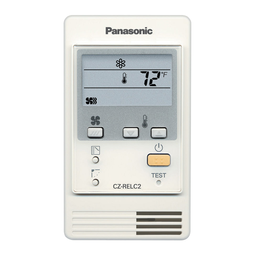
| 1 |
 Simplified remote controller (comes with 200 mm wire) |
1 | 4 |
 Spacers |
2 |
| 5 |
 Wire joints |
2 | |||
| 2 |
 Machine screws M4 × 25 |
2 | |||
| 6 |
 Operating Instructions |
1 | |||
| 3 |
 Wood screws |
2 |
Simplified remote controller installation guidelines
Place of installation
SWITCHING THE ROOM TEMPERATURE SENSOR
The room temperature sensor is placed both in the indoor unit and the simplifi ed remote controller respectively. Either sensor can be used to sense the room temperature.
The indoor unit sensor is usually used.
If you use the simplifi ed remote controller to sense the room temperature, switch the remote controller sensor switch (RCU. SNS) on the PCB of the simplifi ed remote controller from OFF to ON. See the diagram below.

(Fig. 1)
How to install the simplified remote controller
| NOTE1 | Do not twist the simplifi ed remote controller wiring with the power wiring or run it in the same metal conduit, because this may cause malfunction. |
| NOTE 2 | Install the simplifi ed remote controller away from sources of electrical noise. |
| NOTE 3 | Install a noise fi lter or take other appropriate action if electrical noise aff ects the power supply circuit of the unit. |
- Use an electric junction box (supplied locally) (See Fig. 2) for fl ush mounting of the simplified remote controller.


( Fig. 2)
When mounting the back case, tighten the screws securely until the screw heads touch the back case. Otherwise, a loose screw head may damage the PCB on the back of the top cover when mounting the top cover. But do not over-tighten the screws. Overtightening may deform the back case and cause the unit to fall.

(Fig. 3)
- Connect locally supplied 2 core lead wires to the lead wires from the simplifi ed remote controller. (See "How to wire the simplifi ed remote controller.")
When connecting the locally supplied 2 core lead wires to the terminal block, check the terminal numbers in the indoor unit to make sure that the wires are correctly connected. (See Fig. 4)
(The simplifi ed remote controller is damaged if 220 / 240 V AC is applied.)
How to wire the simplified remote controller
Connection diagram
 (Fig. 4)
*1: Use 0.5 mm2 to 1.25 mm2 stranded wires.
Remote controller wiring can be extended to a maximum of 500 m.
How to connect lead wires
| 2 supplied white wire joints |
Lead wire from indoor unit
|
|


(Fig. 5)
Remote controller test run setting
- Push the tip of a ball-pointed pen, etc. into the hole marked "TEST" for more than 4 seconds and press the
![]() (ON/OFF) button.
(ON/OFF) button.
- Perform test run in any operation mode of "heat," "cool" or "fan."
Note: The outdoor unit does not operate for 3 minutes after stopping operation or turning on the unit. - After fi nishing the test run, push the tip of a ball-point pen, etc. into the hole marked "TEST" again until "TEST" disappears from the crystal display.
(The 60-minute off timer function is provided for this remote controller in order to avoid continuous test run.)

Documents / ResourcesDownload manual
Here you can download full pdf version of manual, it may contain additional safety instructions, warranty information, FCC rules, etc.


