Quick Links
INSTALLATION AND MAINTENANCE INSTRUCTIONS
NZM-100 Interface Module
SPECIFICATIONS
Normal Operating Voltage:
Maximum Current Draw:
Average Operating Current:
EOL Resistance:
Maximum IDC Resistance:
External Supply Voltage (between Terminals T10 and T11)
Regulated DC Voltage:
Ripple Voltage:
Alarm Current:
Standby Current:
Temperature Range:
Humidity:
Dimensions:
Accessories:
BEFORE INSTALLING
This information is included as a quick reference installation guide. Refer to
the control panel installation manual for detailed system information. If the
modules will be installed in an existing operational system, inform the opera-
tor and local authority that the system will be temporarily out of service. Dis-
connect power to the control panel before installing the modules.
NOTICE: This manual should be left with the owner/user of this equipment.
GENERAL DESCRIPTION
The NZM-100 Interface Module is intended for use in addressable two-wire
systems, where the individual address of each module is selected using the
built-in rotary switches. This module allows addressable panels to interface
and monitor two-wire conventional smoke detectors. It transmits the status
(normal, open, or alarm) of one full zone of conventional detectors back to
the control panel. All two-wire detectors being monitored must be UL compat-
ible with this module. The NZM-100 has a panel controlled LED indicator and
can be used to replace an M302 module in existing systems.
COMPATIBILITY REQUIREMENTS
To ensure proper operation, these modules shall be connected to listed com-
patible system control panels only.
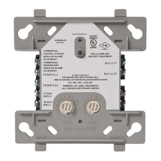
FIGURE 1. CONTROLS AND INDICATORS
15 to 32 VDC
5.1 mA (LED on)
270 µA (LED flashing)
3.9K ohms
25 Ohms
24 VDC power limited
0.1 Volts RMS maximum
90 mA per module
13 mA Maximum @24 VDC
32˚F to 120˚F (0˚C to 49˚C)
10% to 93% Non-condensing
4.5˝ H × 4˝ W × 1.25˝ D (Mounts to a 4˝ square by 2.125˝ deep box.)
SMB500 Electrical Box
C0909-01
MOUNTING
The NZM-100 mounts directly to 4-inch square electrical boxes. (See
Figure 2A.) The box must have a minimum depth of 2.125˝. Surface mounted
electrical boxes (SMB500) are available.
FIGURE 2A. MODULE
MOUNTING
WIRING
NOTE: All wiring must conform to applicable local codes, ordinances, and
regulations. This module is intended for power-limited wiring only.
1.
Install module wiring in accordance with the job drawings and appropri-
ate wiring diagrams.
2.
Set the address on the module per job drawings.
3.
Secure module to electrical box (supplied by installer), as shown in
Figure 2A.
1
12 Clintonville Road
Northford, CT 06472-1653
Phone: 203.484.7161
FIGURE 2B
ISOLATED
QUADRANT
C1044-00
I56-3505-003
7/1/2022

Related Manuals for Honeywell NOTIFIER NZM-100


Summary of Contents for Honeywell NOTIFIER NZM-100
- Page 1 INSTALLATION AND MAINTENANCE INSTRUCTIONS 12 Clintonville Road NZM-100 Interface Module Northford, CT 06472-1653 Phone: 203.484.7161 SPECIFICATIONS Normal Operating Voltage: 15 to 32 VDC Maximum Current Draw: 5.1 mA (LED on) Average Operating Current: 270 µA (LED flashing) EOL Resistance: 3.9K ohms Maximum IDC Resistance: 25 Ohms External Supply Voltage (between Terminals T10 and T11)
- Page 2 DO NOT LOOP WIRE UNDER TERMINALS. BREAK ALL WIRE RUN TO PROVIDE SUPERVISION OF CONNECTIONS. DETECTORS MUST BE UL LISTED COMPATIBLE WITH MODULE. INSTALL DETECTORS PER MANUFACTURER’S INSTALLATION INSTRUCTIONS. C0993-00 NOTIFIER® is a registered trademark of Honeywell International, Inc. I56-3505-003 ©2022 Notifier. 7/1/2022...