
Related Manuals for Honeywell Notifier NFG-8


Summary of Contents for Honeywell Notifier NFG-8
- Page 1 NFG-8 Installation and Operation Manual Central Gas Detection ATEX and SIL1 certified...
-
Page 2: Table Of Contents
INDEX ..............................1 INTRODUCTION ..........................2 1.1) Technical specifications ......................2 INSTALLATION ..........................3 2.1) Assembly and connections ..................... 3 2.1.1) Central overview and parts identification ................5 2.1.2) Central board layout ......................6 2.2) Detector connection ........................ 7 NFG-16REL : 16 relay board (optional) ................... 7 2.3) Programming from PC ...................... - Page 4 Warnings THIS MANUAL SHOULD BE READ CAREFULLY BY ALL PERSONS WHO HAVE OR WILL HAVE RESPONSIBILITY FOR THE INSTALLATION, USE OR SERVICE OF THIS PRODUCT. As with any instrument, this product will function properly only when installed, used and checked as prescribed by the manufacturer.
-
Page 5: Introduction
INTRODUCTION The extremely innovative and versatile NFG-8 gas detection control unit is the ideal solution for small systems with up to 16 gas detectors. The system provides for the connection of 8 detectors with 4-20mA output directly to the control unit. -
Page 6: Installation
National regulations This equipment must be installed and operated in accordance with these instructions and the regulations in force at the place of installation. INSTALLATION 2.1) Assembly and connections Remove the 4 screws located at the 4 corners of the box and remove the front of the control unit box. - Page 7 In addition, if you want to monitor the battery connection, you can connect two more faston jumpers as shown in Figure 2.1 b). PAGE - 4 Installation and Operation NFG-8 NOTIFIER ITALY Manual Doc. M-040.1-NFG8-EN NFG-8_manu-inst_ITA Rev A.3...
-
Page 8: Central Overview And Parts Identification
2.1.1) Central overall view and identification of parts. Power supply (27 Vdc 4A) Relay outputs Batteries 2 x 12V 7Ah (not 8 inputs 4- included) RS232 and USB serial 20mA port RS485 bus connection Fig. 2-3) Central overview and parts identification NFG-8 Installation and Operation PAGE - 11... -
Page 9: 2) Central Board Layout
Dip-switch 8 Function If positioned in ON, when the control unit is switched on, the following are displayed restore data to default Normal position 2.1.2) Central board layout LANGUAGE SW 1 Baud Rate for up/down load via English software 9600 Bit/sec. Italian Spanish 19200 Bit/sec. -
Page 10: Detector Connection
2.2) Detector connection The detectors with 4-20 mA analog output are connected to the control unit, directly on the main board. For connection, the detector with 4-20 mA analog output requires a 3-conductor cable; 2 conductors for the power supply and one conductor for the 4-20 mA signal. The typical cable suggested is a 3 x 0.75 shielded cable that allows to reach a distance up to 100 mt between the gas detector and the control unit. - Page 11 9 13 152637 PAGE - 8 Installation and Operation NFG-8 NOTIFIER ITALY Manual Doc. M-040.1-NFG8-EN NFG-8_manu-inst_ITA Rev A.3...
- Page 12 2.3) PC programming The NFG-8 control unit can be programmed only by means of a Personal Computer with special software. The software has been studied for a simple and fast programming. The connection with the PC is via the RS232 serial port or via USB available on the main board of the control unit.
-
Page 13: System Start-Up And Operation
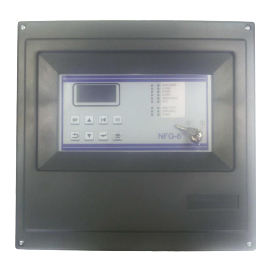
SYSTEM START-UP AND OPERATION This chapter describes the procedures for operating the NFG-8 control unit. The NFG-8 control unit can be programmed only by means of a Personal Computer with the appropriate software. Fig. 3-10) Central front panel 3.1) Ignition After checking that the system has been installed correctly, the NFG-8 control unit can be switched on. -
Page 14: System States
Programming can only be done via Personal Computer with a special program. See chapter 4. For a system already configured, the screen in normal conditions will be the display of the channels (gas detectors) programmed. Maximum 3 channels per screen. Fig. - Page 15 System states The system may be in one of the following operating states: NORMAL ALARM FAULT TEST DISCONNEC EMERGENCY NORMAL It is the normal working status of the central unit, in absence of alarms and faults. The screen in this status will be the visualization of the channels (gas detectors) with the gas concentration measured in real time.
- Page 16 In case there are Alarms from more than one gas detector the alarm screen will present the information of the different channels, as follows: • The information is sorted according to its importance: Off-Scale, Alarm3, Alarm2, Alarm1; • Off-Scale is considered an Alert state with the highest importance. By selecting an Alarm event and pressing the Enter key, a further screen will appear showing the details of the event.
- Page 17 Fig. 3-7) Fault event details TESTING/MAINTENANCE This state is active when one or more channels are in TEST mode and is used to perform maintenance on the gas detection system. To put one or more channels in TEST mode the user must perform a special procedure, described later in the manual. The gas concentration measured by a sensor in TEST will be shown on the central unit display but will not generate an Alarm status if it exceeds a set threshold.
-
Page 18: Menu
3.3) MENU In normal status, in the main screen appears the list of gas detectors managed by the central unit. Pressing the MENU button, the sub-menus described below will appear with the relative function. INSERT changes the status of the sensors and/or relays from Off to DISINSERT changes the status of the sensors and/or relays from switched on to switched off. - Page 19 press RST (Reset) to restore the central unit to normal status (this is possible only if ACK has been performed before and if the gas detector is no longer in alarm and/or fault status) PAGE - 16 Installation and Operation NFG-8 NOTIFIER ITALY Manual...
- Page 20 At the occurrence of an event (alarm or fault), the buzzer of the central unit will sound and the display will pass to the visualization of the page Active Events where there will be the indication of the sensor in Alarm and/or Fault. To silence the central unit buzzer, turn the key to the central position (ACK) and press the ACK key, the central unit buzzer will stop sounding and an X will appear on the event line on the right.
-
Page 21: Software Configuration From Pc
SOFTWARE CONFIGURATION FROM PC 4.1) Introduction The PC configuration software is a simple and complete interface for programming the NFG-8 control unit. The software is used for: • Load data from the control unit and check its programming and event memory •... -
Page 22: 1) Central Selection
When first using the program, after installation, the only existing user is Notifier with a default password. The Notifier user is named Administrator and has the highest level that allows access to all program functions. Then enter in the window of fig. 4.2: User name: notifier Password:... - Page 23 Fig. 4.3.1 a) Central selection screen Fig. 4.3.1 b Control unit selection screen Select the control unit to be programmed: NFG-8 NFG-8 + NFG-16R In case you do not know the model of the central unit you have to program, it is possible through the option DETECT that the software automatically sets the model of the central unit.
-
Page 24: Program Main Screen
4.3.2) Program main screen Fig. 4.3.2 a) Program main screen (Administrator level user) New configuration to create a new system configuration Open file to open an existing configuration Serial port sets up a PC serial port for data transfer from and towards the connected central unit Test performs a test of the PC >... -
Page 25: 1) File
4.4.1) Files Fig. 4.4.1 a) File menu to create a new plant configuration Open to open an existing configuration Fig. 4.4.1 b) Opening an existing plant file Open Event Memory to display historical files of events previously loaded by the central unit (Menu: Communication submenu: Load Event Memory from CPU). - Page 26 Fig. 4.4.1 c) Opening an event history file From "Open event memory" it is possible to open an event file previously loaded and saved in the appropriate folder. Fig. 4.4.1 d) Path to an event history file *.elog Fig. 4.4.1 e) List of events in memory Information on reading the event history see: Menu: Communication submenu: Load event memory from CPU.
- Page 27 With "Compare" you compare the plant file of the current session with a previously created one. By clicking on the "Compare" function, a window appears where you can choose the path to the file to be compared. Fig. 4.4.1 f) Path of a plant file to compare Fig.
-
Page 28: 2) Settings
4.4.2) Settings Fig. 4.4.2 a) Settings menu With "Serial port" you select the serial port of the PC for loading and unloading data. Select the communication speed with the PC (Baud rate) as set on the control unit. "Language" to choose the language of the "NFG-8" software. While you are creating or editing a plant configuration, remember to save using "Save"... -
Page 29: 4) Communication
Fig. 4.4.3 b) Application Log Window 4.4.4) Communication Fig. 4.4.4 a) Communication menu In the "Communication" menu you set the parameters for data exchange between the PC with the software and the NFG-8 control unit. Preamble: in order to be able to carry out the data exchange between the PC and the NFG-8 control unit, the connection between the two devices is essential. - Page 30 SWITCH Rs232 Fig. 4.4.4 b) Serial and USB ports on the control unit board The diagram of the serial cable to be used is shown on page 7. The "Test Command" is used to check the correct connection between the control unit and the PC.
- Page 31 Fig. 4.4.4 d) Change Serial Password "Download configuration in the Central Unit" allows to download the plant file created in the NFG-8 Central Unit. Fig. 4.4.4 e) Message requesting the saving of the central event memory Before starting the data loading and unloading procedure, a warning message asks if you want to save the event memory of the central unit.
- Page 32 "Load configuration from CPU" is the opposite procedure to data downloading. It allows you to load the system file (programming resident in the control unit) from the control unit. The sequence of operations is the same as for data download, see above. At the end of the data loading, the plant file is automatically saved in the appropriate PC folder.
- Page 33 Fig. 4.4.4.i) Events history screen Below is an explanation of the different columns identification number of the event. It can be used for comparison with the event in the NFG-8 control unit. Date date and time of the event Event Type type of event.
-
Page 34: 5) Report
Zone plant zone Channel identifier of the channel (detector) that generated the event At the top of the screen you can also enter search filters to optimize the display of the event list below. The filters can be by event type and/or by date and time. If a printer is connected to the PC, you can use the PRINT button to print the event list. -
Page 35: 1) System Information
Warning: load the last saved version of a NFG8 central unit configuration file. If you are not sure to have in your computer the last configuration version of the NFG-8 central unit on which you are operating, load the programming of the central unit through the command "Load configuration from CPU"... -
Page 36: 2) General Settings
4.5.2) General settings Fig. 4.5.2) General settings screen In "General Settings" you set up "Heating time": stand by time of the central unit, immediately after the power on, before being operative "Slave address": the address of the central unit for communication: DO NOT MODIFY "Maintenance time"... - Page 37 Fig. 4.5.3 a) Channel summary map (detectors) The Channel Overview gives a summary picture of the sensors of the NFG-8 system, of how many of them are defined (rectangle with the data inside). Different colors represent the different detector modes: undefined, defined, redundant, etc. To have a summary of the programming data of each channel, pass over it with the mouse and a summary window will appear with the channel parameters.
- Page 38 Channel management Fig. 4.5.3 c) Detector programming screen Programming a channel (gas detector) An input channel (gas detector) is programmed mainly by entering data in three main fields in the "Detector" option: 1) The profile specifies the unit of measurement to be set according to the type of gas to be detected and the type of detector connected.
- Page 39 Fig. 4.5.3 d) Channel details screen The available profiles are: - L.I.E. (Lower Explosive Limit) - Oxygen deficiency - Oxygen enrichment - Oxygen for inerting - Oxygen mixed mode - Toxic Gases In "Gas Type" you choose the gas to be detected from a proposed list. The gases in the list are only those allowed by the previously selected "Profile".
- Page 40 Fig. 4.5.3 e) Alarm threshold setting screen The up arrow to the left indicates increasing alarm values for the LEL profile. Alarm values 1 to 3 correspond to an increase in gas concentration. The configuration software checks that the data entered by the person doing the programming is correct.
-
Page 41: 4) Relays (Outputs)
4.5.4) Relays (Outputs) The "Relays" menu is used to enable and program the characteristics of the outputs that are part of the system. Relay overview Fig. 4.5.4 a) Relay overview screen The Relay overview (outputs) gives a summary picture of how many outputs the NFG- 8 system is composed of, how many of them are defined (rectangle with data inside). - Page 42 Fig. 4.5.4 b) Output details window that appears when you move the mouse over it Relay management Fig. 4.5.4 c) Output programming screen NFG-8 Installation and Operation PAGE - 11 NFG-8_manu-inst_ITA Manual Doc. M-040.1-NFG8-EN NOTIFIER ITALY Rev A.3...
- Page 43 The Relay screen allows you to program the outputs. The available options are: Events programming of the event that activates the output Operating mode output operating mode (instantaneous, impulsive, timed). Event type selects the type of event that can be associated with the output: Sensor event (Alarm, Fault, Low value, etc.) or Generic event (Alarm, Fault, Mains failure, Low battery, etc.).
- Page 44 Pressing the Add/Delete button, the Choose Sensor window will open where to select the sensor address or addresses to associate with the output. The padlock shown to the left of the Event Type list indicates whether the relay output is stored or not.
- Page 45 Fig. 4.5.4 h) Generic events selection window (system events) OR and AND functions Fig. 4.5.4 (i) OR and AND functions OR function In this way, it is sufficient for one of the events in the list to occur to activate the output (OR function).
- Page 46 AND function Fig. 4.5.4 l) Output programming window with AND option With the OR function, to activate the output programmed in this way, all that is needed is one of the events associated with the output and present in the Associated Sensors list.
- Page 47 Fig. 4.5.4 m) Output operating mode Instantaneous follows the status of the event: Event active: (detector in alarm) output activated (after a possible delay); event reset: output deactivated (after any delay time) Output operation mode Steady activated until the channel restore + the Deactivation Delay Activation Delay...
- Page 48 Fig. 4.5.4 n) Operating mode NFG-8 Installation and Operation PAGE - 11 NFG-8_manu-inst_ITA Manual Doc. M-040.1-NFG8-EN NOTIFIER ITALY Rev A.3...
- Page 49 APPENDIX - NFG-8 BATTERY CARD CONNECTION 1. DISCONNECT ALL CABLES FROM THE BATTERIES AND REMOVE JP47 TERMINAL BLOCK (THE CONTROL UNIT SWITCHES OFF) 2. CONNECT THE BATTERY CARD TO BATTERY 1 RESPECTING THE POLARITY (RED POSITIVE) (BLUE NEGATIVE), ONCE CONNECTED THE GREEN LED WILL LIGHT UP.
- Page 50 3. CONNECT THE NEGATIVE FASTON COMING FROM FROM THE POWER SUPPLY TO THE NEGATIVE SIDE OF THE BOARD. 4. CONNECT THE JTAB2 FASTON TO THE POSITIVE OF THE BOARD NFG-8 Installation and Operation PAGE - 11 NFG-8_manu-inst_ITA Manual Doc. M-040.1-NFG8-EN NOTIFIER ITALY Rev A.3...
- Page 51 5. CONNECT THE JTAB1 FASTON ON THE NEGATIVE OF THE BATTERY 2 6. CONNECT THE POSITIVE FASTON COMING FROM FROM THE POWER SUPPLY TO THE BATTERY POSITIVE 2 PAGE - 48 Installation and Operation NFG-8 NOTIFIER ITALY Manual Doc. M-040.1-NFG8-EN NFG-8_manu-inst_ITA Rev A.3...
- Page 52 7. INSERT TERMINAL JP47 THE CONTROL UNIT SWITCHES ON AGAIN WITH THE BATTERY CONTROL CARD NFG-8 Installation and Operation PAGE - 11 NFG-8_manu-inst_ITA Manual Doc. M-040.1-NFG8-EN NOTIFIER ITALY Rev A.3...
- Page 53 PAGE - 50 Installation and Operation NFG-8 NFG-8_manu-inst_ITA NOTIFIER ITALY Manual Doc. M-040.1-NFG8-EN Rev A.3...
- Page 54 Via Grandi, 22 E-mail: [email protected] A Honeywell company Numero Assistenza Tecnica: 039-9301410 Every care has been taken in the preparation of this data sheet but no liability can be accepted for the use of the information therein. Design features may be changed or amended without prior notice.