
Related Manuals for Honeywell NOTIFIER SCS Series


Summary of Contents for Honeywell NOTIFIER SCS Series
- Page 1 Smoke and HVAC Control Station SCS Series Operation and Installation Manual Document 15712 7/18/16 Rev: P/N 15712:L ECN 17-181...
- Page 2 Fire Alarm & Emergency Communication System Limitations While a life safety system may lower insurance rates, it is not a substitute for life and property insurance! An automatic fire alarm system—typically made up of smoke (caused by escaping gas, improper storage of flammable materi- detectors, heat detectors, manual pull stations, audible warning als, etc.).
- Page 3 LiteSpeed™ and Lite-Connect™ are trademarks; and Fire-Lite® Alarms, Honeywell®, and SWIFT® are registered trademarks of Honeywell International Inc.HARSH™, NIS™, and NOTI•FIRE•NET™ are all trademarks; and Acclimate® Plus™, eVance®, FlashScan®, FAAST Fire Alarm Aspiration Sensing Technology®, Honeywell®, Intelligent FAAST®, NOTIFIER®, ONYX®, ONYXWorks®, SWIFT®, VeriFire®, and VIEW®...
- Page 4 •Brief description of content you think should be improved or corrected •Your suggestion for how to correct/improve documentation Send email messages to: [email protected] Please note this email address is for documentation feedback only. If you have any technical issues, please contact Technical Services.
-
Page 5: Table Of Contents
Table of Contents Section 1: About This Manual....................9 1.1: Standards and Other Documents........................9 1.2: UL 864 Compliance.............................10 1.2.1: Products Subject to AHJ Approval....................10 1.2.2: Application Not Consistent with UL and NFPA Standards ..............10 1.3: Supplemental Documentation........................10 1.4: Cautions and Warnings ..........................11 1.5: Manual Conventions ............................11 Section 2: Concepts of Smoke Control ................ - Page 6 Table of Contents 3.3.1: Inventory............................36 3.4: Preliminary SCS-8⁄SCE-8 Design Considerations..................36 3.4.1: Related Documentation ........................36 3.4.2: Fan and Damper Operation with the SCS-8 ..................37 3.4.3: Design Considerations ........................37 3.4.4: Selecting Fan and Damper Capabilities.....................37 3.4.5: Switch Group Type..........................38 3.4.6: Switch Group Type Configuration ....................38 3.4.7: Dipswitch Setting..........................40 3.4.8: EIA-485 Addressing ..........................40 3.4.9: Point Assignment..........................41...
- Page 7 Table of Contents Control and Monitor Module Programming..................83 Software Type Identification........................84 Control-By-Event ..........................84 EIA-485 Protocol Point Mapping......................85 Optional Feature Programming for Control and Monitor Modules .............86 Full Point Programming ........................86 3.10: Building-Specific Operation and Programming Examples ...............87 3.10.1: Dedicated System Design........................88 Preliminary Design Considerations......................88 Installation ............................90 Programming (AM2020/AFP1010 Example) ..................90...
- Page 8 Table of Contents Example # 2: General Alarm ......................199 Example # 3 ............................200 Example # 4: Fire Floor, Floor Above, Floor Below .................200 Appendix B: Miscellaneous Information ................201 B.1: NFS-320 and NFS2-640 Control-By-Event ....................201 B.2: NFS2-3030 Control-By-Event ........................201 B.3: NCA-2 Operation ............................201 B.4: Appendix D SCS⁄SCE Worksheets......................201 B.5: Compatibility with Other Systems ......................201 Appendix C: Special Applications ..................
-
Page 9: Section 1: About This Manual
Section 1: About This Manual 1.1 Standards and Other Documents This Fire Alarm Control Panel complies with the following NFPA standards: NFPA 12 CO2 Extinguishing Systems NFPA 12A Halon 1301 Extinguishing Systems NFPA 13 Sprinkler Systems NFPA 15 Water Spray Systems NFPA 16 Foam/Water Deluge and Foam/Water Spray Systems NFPA 17 Dry Chemical Extinguishing Systems NFPA 17A Wet Chemical Extinguishing Systems... -
Page 10: Ul 864 Compliance
About This Manual UL 864 Compliance 1.2 UL 864 Compliance 1.2.1 Products Subject to AHJ Approval This product has been certified to comply with the requirements in the Standard for Control Units and Accessories for Fire Alarm Systems, UL 864 9th Edition. Operation of this product with products not tested for UL 864 9th Edition has not been evaluated. Such operation requires the approval of the local Authority Having Jurisdiction (AHJ). -
Page 11: Cautions And Warnings
Cautions and Warnings About This Manual 1.4 Cautions and Warnings This manual contains cautions and warnings to alert the reader as follows: CAUTION: INFORMATION ABOUT PROCEDURES THAT COULD CAUSE PROGRAMMING ERRORS, RUNTIME ERRORS, OR EQUIPMENT DAMAGE. WARNING: INDICATES INFORMATION ABOUT PROCEDURES THAT COULD CAUSE IRREVERSIBLE DAMAGE TO THE CONTROL PANEL, IRREVERSIBLE LOSS OF PROGRAMMING DATA OR PERSONAL INJURY. -
Page 12: Section 2: Concepts Of Smoke Control
Section 2: Concepts of Smoke Control 2.1 Introduction Section 2: serves as a general outline of the concepts, components, and implementation of a smoke control system. The user should be famil- iar with the following documents, codes, and standards and refer to them for additional information: •... - Page 13 Introduction Concepts of Smoke Control Smoke Barrier. A vertical or horizontal membrane, such as a wall, floor, or ceiling assembly, that is designed and constructed to resist the movement of smoke. A smoke barrier may or may not have a fire resistance rating. Smoke barriers may have openings protected by closing devices or adequate air flows.
-
Page 14: 2: Abbreviations
Concepts of Smoke Control Smoke Movement 2.1.2 Abbreviations In order to simplify system configuration discussions and technical illustrations, the following abbreviations are used for control modules and monitor modules. These are in addition to industry-wide abbreviations already specified in the Definitions section. Table 2.1 Chart of Abbreviations Code Term... -
Page 15: 2: Buoyancy
Smoke Movement Concepts of Smoke Control In a building with reverse stack effect, only relatively cool smoke will follow the downward tendency of air into the shaft. If a smoldering fire occurs on a floor above the neutral plane during reverse stack effect conditions, the smoke will travel into and down the shaft and deposit itself on the floors below the neutral plane. -
Page 16: 6: Hvac Systems
Concepts of Smoke Control Principles of Smoke Control 2.2.6 HVAC Systems Before the development of smoke control, HVAC systems were shut down when fires were discovered for two main reasons: • The HVAC system frequently aided the movement of smoke during a fire condition, transporting smoke to every area that it serves. •... -
Page 17: 2: Purging
General System Components Concepts of Smoke Control Figure 2.5 Airflow 2.3.2 Purging Although Pressurization and Airflow have been discussed as the two methods for controlling smoke, it will not always be possible to main- tain airflows sufficient to prevent smoke from moving through open doors into a protected area. Ideally, doorways will be open for only short periods of time during evacuation. -
Page 18: 1: Hvac Equipment
Concepts of Smoke Control General System Components 2.4.1 HVAC Equipment HVAC Systems Whether serving the dual purpose of maintaining the environmental conditions in the building and controlling smoke in a fire situation (Non- dedicated System), or the sole purpose of controlling smoke (Dedicated System) - HVAC systems can usually be adapted for smoke control. When used for smoke control applications, HVAC systems must have the following capabilities: •... - Page 19 General System Components Concepts of Smoke Control Dual Duct Systems. Dual duct systems have separate heating and cooling coils, each located in a separate com- partment. These types of systems also have separate ducts to supply hot and cold air from each coil compartment to mixing boxes.
-
Page 20: Ductwork
Concepts of Smoke Control General System Components Ductwork Ductwork is constructed of a variety of materials including steel, aluminum, concrete, and masonry. Ductwork usually connects the fans with the areas to be served. Air travels from the supply fan through the supply ducts into the building. Return air is often pulled through the ple- num space above the ceiling as shown in Figure 2.11a. -
Page 21: Dampers
General System Components Concepts of Smoke Control fans can be of single thickness or airfoil design. Tubeaxial fans are used to provide low- to medium-pressures for HVAC applications. Vaneaxial fans are capable of operating at higher pressures than tubeaxial fans. Blades of vaneaxial fans can be of single thickness or airfoil design. -
Page 22: 2: Control Equipment
Concepts of Smoke Control Smoke Control System Types 2.4.2 Control Equipment Fire Alarm Control Panel (FACP). If necessary, the FACP and related equipment should work in cooperation with the smoke control sys- tem and not counteract its operation. Normally, detection of a fire by a smoke detector will cause the activation of the smoke control system. Since the detector is usually controlled and monitored by the FACP, some communication between the FACP and the smoke control system may be necessary. -
Page 23: Basic System Descriptions
Smoke Control System Types Concepts of Smoke Control Definitions are given below for dedicated and non-dedicated systems, shaft and floor protection. Detailed explanations of Stairtower Pressur- ization, Elevator Hoistway, and Zoned Smoke Control Systems follow the definitions. Smoke Control Systems Dedicated Non-dedicated System... -
Page 24: Single Injection
Concepts of Smoke Control Smoke Control System Types Single Injection A single-injection system supplies air for pressurization at one location in the stairtower, usually at the top as shown in Figure 2.15a. One of the main concerns with single-injection systems is that the pressurization of the stairtower could fail when a few doors near the supply fan are open. -
Page 25: 2: Elevator Hoistway Systems
Smoke Control System Types Concepts of Smoke Control 2.5.2 Elevator Hoistway Systems Elevator hoistways have been known to adversely contribute to the movement of smoke throughout a building. This is due mainly to the fact that elevator doors are not tight fitting and elevator hoistways usually have openings or vents at the top. In addition to these factors, the major contributor to smoke movement in an elevator hoistway is the stack effect of the building. - Page 26 Concepts of Smoke Control Smoke Control System Types An alternate way to achieve lobby protection is direct pressurization of the elevator lobbies, as shown in Figure 2.18. Direct pressurization of the lob- bies tends to provide better protection for the lobbies because higher pres- sures in that area can be achieved.
-
Page 27: 3: Zoned Smoke Control Systems
Smoke Control System Types Concepts of Smoke Control 2.5.3 Zoned Smoke Control Systems Buildings can usually be divided into a number of smoke control zones where each zone can be separated from the smoke zone to prevent the movement of smoke. The smoke control zone boundaries are usually partitions, floors, and doors that can be closed. Often each floor of a building is chosen as a smoke control zone boundary. -
Page 28: Mechanical Exhaust
Concepts of Smoke Control Smoke Control System Types Mechanical Exhaust Zoned smoke control using mechanical exhaust is very similar to the smoke shaft method and similarly is done in conjunction with pressur- ization of nonsmoke zones. The driving force of smoke movement for the smoke shaft method is buoyancy. However, when the flow of smoke through the smoke shaft is aided by mechanical fans, the method is known as mechanical exhaust. -
Page 29: Basic Smoke Control System Operation
Basic Smoke Control System Operation Concepts of Smoke Control Zoned smoke control can also be accomplished in situations where an HVAC system serves only one smoke control zone. An example would be a three floor building where each floor is a separate smoke control zone that has a separate HVAC system serving each floor. Zoned smoke control can be achieved by putting the HVAC system in the modes listed below: •... - Page 30 Concepts of Smoke Control Basic Smoke Control System Operation (S1), ensuring that the return damper (R1) is open, and turning on the return fan. Pressurization of all other areas is accomplished by closing the return dampers, ensuring that the supply dampers are open, and turning on the supply fan. This example is using zoned smoke control with mechanical exhaust.
- Page 31 Basic Smoke Control System Operation Concepts of Smoke Control These steps would be accomplished as follows: Turn ON the stairtower and elevator hoistway fans. CLOSE return dampers for all nonsmoke zones. As an example, if the fire event occured on floor 5, the areas specific to this example would be floors 1-4 and floors 6-8.
-
Page 32: Section 3: The Scs⁄Sce
Section 3: The SCS⁄SCE 3.1 Introduction 3.1.1 Hardware Features The Smoke Control Station (SCS-8) and the optional Smoke Control Expander (SCE-8) are used in conjunction with the following equip- ment, providing the capability to control and display the status of air handling unit (AHU) fans and dampers. •... -
Page 33: 2: Scs V4.0 Software Features
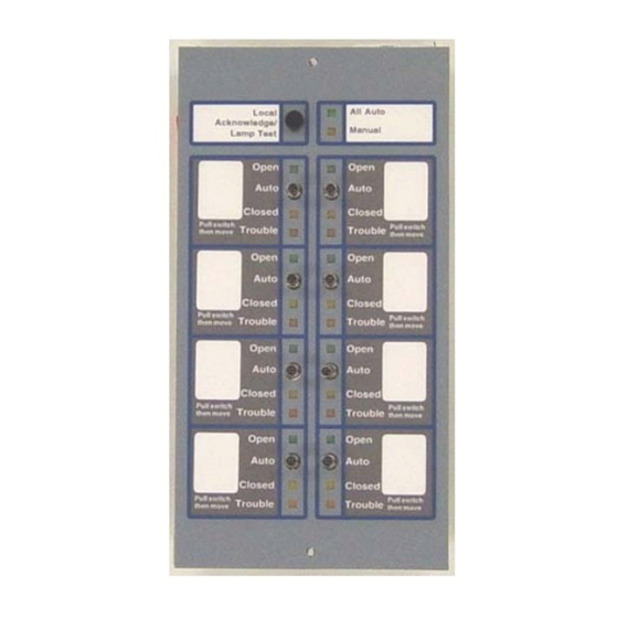
Smoke Control Station (SCS-8) The SCS⁄SCE NOTE: 1. Software Part Numbers 73631 and 73845 are not compatible with INA combinations after M2.7. 2. Part #SCSV2.84 is not compatible with FACP/INA combinations prior to M2.8. 3. NFS-320s, NFS2-640s, NFS-640s, NFS2-3030s, NFS-3030s, NCAs and NCA-2s are only compatible with software #SCS2.84 or higher. (They are not compatible with any 73XXX series software versions.) 4. - Page 34 The SCS⁄SCE Smoke Control Station (SCS-8) Local Acknowledge / Lamp Test momentary switch All AUTO LED (Green) On LED (Green) 3 - position Manual LED (Amber) toggle switch (ON/AUTO/OFF) Switch Group Off LED (Yellow) Trouble LED (Amber) SCS-8 (top view) 8 dipswitches Two rotary decimal address switches...
-
Page 35: Smoke Control Lamp Driver (Scs-8L)
Smoke Control Lamp Driver (SCS-8L) The SCS⁄SCE 3.3 Smoke Control Lamp Driver (SCS-8L) Each SCS-8L has two rotary decimal switches for addressing and 8 dipswitches for mode configuration (see Figure 3.2). The rotary switches and dipswitches are not on the SCE-8L. ON/OFF LED ON/OFF LED (groups 1-4) Connector... -
Page 36: 1: Inventory
The SCS⁄SCE Preliminary SCS-8⁄SCE-8 Design Considerations 3.3.1 Inventory The SCS-8* The SCS-8 Smoke Control Station provides the capability to control and display the status of eight AHU fans and dampers. The SCS-8 is capable of two modes of operation, FSCS for the control of smoke and HVAC for the control of heating, ventilating and air conditioning. -
Page 37: 2: Fan And Damper Operation With The Scs-8
Preliminary SCS-8⁄SCE-8 Design Considerations The SCS⁄SCE 3.4.2 Fan and Damper Operation with the SCS-8 Control of a fan or a damper is achieved through use of a control module (CM). Normally, control modules are used to activate and deactivate notification appli- ances. -
Page 38: 5: Switch Group Type
The SCS⁄SCE Preliminary SCS-8⁄SCE-8 Design Considerations Usually a fan does not need the capability of separate verification of its on/off state (requiring two monitor modules). One monitor module is capable of determining when the fan is on and when it is off. 3.4.5 Switch Group Type Each controlled/monitored fan or damper has one associated switch group on the SCS⁄SCE. - Page 39 Preliminary SCS-8⁄SCE-8 Design Considerations The SCS⁄SCE There is more than one way to comply with the pre-chosen formats for switch group type configuration. Following are some recommenda- tions for configuring switch group types: • Since the configurations are in groups of 16, 8, or 4, break up the total number of a common switch groups into the most convenient size.
-
Page 40: 7: Dipswitch Setting
The SCS⁄SCE Preliminary SCS-8⁄SCE-8 Design Considerations 3.4.7 Dipswitch Setting The eight dipswitches are used to control the function of the SCS⁄SCE. The dipswitches perform the functions as listed in Table 3.4, where: switches 1-5 control the combinations of switch group types; switch 6 controls whether the SCS⁄SCE operates in the FSCS or the HVAC mode;... -
Page 41: 9: Point Assignment
Preliminary SCS-8⁄SCE-8 Design Considerations The SCS⁄SCE 3.4.9 Point Assignment Each toggle switch group of an SCS⁄SCE uses four EIA-485 proto- col points (of the 64 available) to control and monitor a particular fan or damper. Each of the four points is responsible for one of the four capabilities listed in Switch Group Type (CON ON⁄OP , VER... -
Page 42: Cabinet And Chassis Mounting
The SCS⁄SCE Cabinet and Chassis Mounting 3.5 Cabinet and Chassis Mounting Select an appropriate knockout on the enclosure. Mount the cabinet or backbox. Ground the enclosure to a solid metallic ground, such as a grounded cold water pipe. Pull all SCS-8 wiring into the enclosure as illustrated in Figure 3.6. ABS-4D Backbox The ABS-4D may be surface mounted or semi-flush mounted. -
Page 43: Scs-8⁄Sce-8 Installation
SCS-8⁄SCE-8 Installation The SCS⁄SCE 3.6 SCS-8⁄SCE-8 Installation Labels SCS-8⁄SCE-8 Labels have been provided for fan control (ON/OFF) as well as damper control (OPEN/CLOSED). If using the custom display labels, type the appropriate informa- tion in the white square areas provided. Carefully cut out the labels and insert them into the SCS-8⁄SCE-8 by slipping them into the label slots on the back side of the SCS- 8⁄SCE-8 faceplate. - Page 44 The SCS⁄SCE SCS-8⁄SCE-8 Installation Wiring Specifications The EIA-485 circuit cannot be T-Tapped; it must be wired in a continuous fashion from the control panel to the SCS-8. The maximum wiring distance between the panel and the last SCS-8 or annunciator is 6,000 feet @ 16 AWG.
- Page 45 SCS-8⁄SCE-8 Installation The SCS⁄SCE EIA-485 In (–) Back side of board EIA-485 Out (–) EIA-485 Out (+) EIA-485 In Not Used Not Used Common In (–) Common Out (–) Power In (+24 VDC) Power Out (+24 VDC) Earth Ground Figure 3.13 SCS-8 Terminals First SCS-8 or Annunciator _ _ _ _Last SCS-8 Dipswitch 8 ON FACP/Network...
-
Page 46: Power Supply
The SCS⁄SCE SCS-8⁄SCE-8 Installation Power Supply Power for the Smoke Control Station is provided via a separate power loop from the control panel which is inherently supervised (loss of power also results in a communication failure at the control panel). If the SCS-8 is powered remotely, it must be powered by a Power Lim- ited power supply listed for fire protective signaling and there must be a common connection between the negative battery terminals of each supply. -
Page 47: Programming And Testing The Smoke Control Station
SCS-8L⁄SCE-8L Installation The SCS⁄SCE (+) 24 VDC Power to SCS-8 TB1-3 (–) Common to SCS-8 TB1-5 (+) 24 VDC (–) 24 VDC Power Common Regulated power-limiting power supply listed for fire protective signaling. Figure 3.17 Power Supply Connections Programming and Testing the Smoke Control Station This completes the SCS-8⁄SCE-8 installation. -
Page 48: Wiring The Switches
The SCS⁄SCE SCS-8L⁄SCE-8L Installation Wiring the Switches The connectors and pin assignments used to wire switches to the SCS-8L⁄SCE-8L are shown in Figure 3.19. The switches for each switch group wired to J1 and J2 must be single pull, double throw, center-off type as shown in Figure 3.19. The center-off position is used for Auto- matic Control. - Page 49 SCS-8L⁄SCE-8L Installation The SCS⁄SCE The maximum output current for each LED or Lamp is 50 mA if powered by 24 VDC or 20 mA if powered by 5 VDC. NOTE: All LEDs must be located in the same room as the modules. ON/OFF Lamps (groups 5-8 for SCS-8L, groups 13-16 for SCE-8L)
-
Page 50: Installing Relay Modules
The SCS⁄SCE SCS-8L⁄SCE-8L Installation LEDs: Use green for ON, yellow for OFF, amber for Trouble, green for All AUTO and amber for MANUAL Use 680 ohm, 1/4-watt resistors for each point Figure 3.21 LED Connection @ 5 VDC (Using High Efficiency 2mA LEDs) LEDs: Use green for ON, yellow for OFF, amber for... - Page 51 SCS-8L⁄SCE-8L Installation The SCS⁄SCE SCS-8L LDM-R32 SCS-8L LDM-R32 Figure 3.24 LDM Ribbon Cable Connection EIA-485 Communication between the FACP and the SCS-8L is accomplished over a two-wire EIA-485 serial interface. Up to 32 EIA-485 devices may be installed on an EIA-485 circuit. The data communication and wiring are supervised by the fire alarm control panel. All SCS-8L Smoke Control Stations must be in the same room as the FACP/Network Annunciator when in FSCS mode.
-
Page 52: Power Supply
The SCS⁄SCE SCS-8L⁄SCE-8L Installation When the EIA-485 shield is not in conduit: Terminate the shield at the outside of the FACP backbox (ground). Do not allow the shield to enter or even touch the cabinet. Between Smoke Control Stations, wire-nut multiple shields together outside of the respective enclosures. SCS-8L Terminal Block Enclosure... -
Page 53: Electrical Ratings
SCS-8L⁄SCE-8L Installation The SCS⁄SCE First SCS-8L or Annunciator _ __ _ _Last SCS-8L Dipswitch 8 ON FACP/Network Annunciator – – EIA-485 (–) – – EIA-485 (+) Terminate with 120 ohms if required. First SCS-8L or Annunciator _ _ _ _Last Annunciator ELR installed FACP/Network Annunciator... -
Page 54: Programming And Testing The Smoke Control Station
The SCS⁄SCE Configuration Programming and Testing the Smoke Control Station This completes the SCS-8L⁄SCE-8L installation. After programming the fire alarm control panel to accept the SCS-8L⁄SCE-8L, fully test the system to ensure that each switch performs its intended function, each LED lights as required, and that the SCS-8L⁄SCE-8L can perform the functions outlined in Section 3.8.1 “Firefighter's Smoke Control Station (FSCS) Mode”... - Page 55 Configuration The SCS⁄SCE For instance, this particular dipswitch setting allows the SCS⁄SCE to function in the FSCS mode (dipswitch 6 in the ON position). The set- ting for switches 1-5 not only select the FSCS group types of 8 and 1 but configure the switch group layout as shown to the left, where switch groups 1, 4, 5, 8, 9, 12, 13, and 16 are set for group type 8 operation and switch groups 2, 3, 6, 7, 10, 11, 14, and 15 are set for group type 1.
- Page 56 The SCS⁄SCE Configuration When used with an SCE, eight switch groups are available for group type 8 operation and eight are available for group type 1 operation in the format shown to the left. Type 8 switch groups require two control modules and one monitor module.
- Page 57 Configuration The SCS⁄SCE When used with an SCE, all 16 switch groups are available for group type 5 operation. Type 5 switch groups require one control module and one monitor module. Type 5 switch groups can be used for fans or dampers.
- Page 58 The SCS⁄SCE Configuration When used with an SCE, eight switch groups are available for group type 5 operation and eight are available for group type 3 operation in the format shown to the left. Type 5 switch groups require one control module and one monitor module.
- Page 59 Configuration The SCS⁄SCE When used with an SCE, eight switch groups are available for group type 8 operation and eight are available for group type 3 operation in the format shown to the left. Type 8 switch groups require two control modules and one monitor module.
- Page 60 The SCS⁄SCE Configuration When used with an SCE, eight switch groups are available for group type 5 operation and eight are available for group type 1 operation in the format shown to the left. Type 5 switch groups require one control module and one monitor module.
-
Page 61: Toggle Switch Operation For Fscs Mode
Configuration The SCS⁄SCE Toggle Switch Operation for FSCS Mode FSCS ON/AUTO/OFF (OPEN/AUTO/CLOSED) Toggle Switch Operation Each ON/AUTO/OFF toggle switch will function according to Table 3.6 for non-alarm conditions and Table 3.7 for alarm conditions. Plac- ing a toggle switch in the ON or OFF position will activate/deactivate the control points as shown. Once this has occurred, further control- by-event processing at the FACP is inhibited. -
Page 62: Switch Group Leds For Fscs Mode
The SCS⁄SCE Configuration Table 3.7 FSCS Toggle Switch Functions (Alarm Condition) Activates CON depends on CBE after Reset Deactivates CON ON⁄OP ON⁄OP Deactivates CON Activates CON OFF⁄CL OFF⁄CL Activates CON depends on CBE after Reset Deactivates CON ON⁄OP ON⁄OP Deactivates CON Activates CON OFF⁄CL OFF⁄CL... -
Page 63: Dedicated System Operation
Configuration The SCS⁄SCE NFS2-3030 with or without NCA-2: Annunciator points 33-64 are not programmed to an unused output point and the SCE-8 is not connected. During this condition, an annunciator trouble will be displayed at the control panel. (EXPANDER CONFIG) •... -
Page 64: Non-Dedicated System Operation
The SCS⁄SCE Configuration Program the FACP to activate the CON CM (if present) whenever the CON CM is inactive using a CBE equation for the OFF/CL ON/OP OFF/CL Equations must be written to do all of the following steps for a control point within a toggle switch group type, if only an OFF control mod- ule is present: Program the FACP using CBE equations to establish the automatic control state (when the Dedicated System is not controlling smoke) of the CON... -
Page 65: 2: Heating, Ventilating & Air Conditioning (Hvac) Mode
Configuration The SCS⁄SCE Manual Control Manual actions may be taken to override the automatic functions. Moving any switch on the SCS⁄SCE out of the automatic position (ON/OFF) will cause the FSCS to enter the manual control state. In this state, any further automatic operation is inhibited for the respective SCS⁄SCE. -
Page 66: Scs Dipswitch Settings For Hvac Mode
The SCS⁄SCE Configuration Table 3.9 HVAC Mode Switch Group Types , VER and VER Turn a fan off (close a damper) and verify when the fan is on and off (damper OFF⁄CL ON⁄OP OFF⁄CL open and closed) Turn a fan on (open a damper) ON⁄OP and VER Turn a fan on (open a damper) and verify when the fan is off (damper closed) - Page 67 Configuration The SCS⁄SCE The SCE will not function with dipswitches selected No Function - Factory Setting as shown on the right. This is a factory setting that must be changed in order for the SCS to function properly. When used with an SCE, all 16 switch groups are available for group type 1 operation.
- Page 68 The SCS⁄SCE Configuration When used with an SCE, all 16 switch groups are available for group type 7 operation. Type 7 switch groups require one control module and two monitor modules. Type 7 switch groups are usually only used for dampers. The control module is used for CLOSED control of a damper, one monitor module is used for the OPEN verification of the damper and the other monitor module is used for the CLOSED verification of the damper.
- Page 69 Configuration The SCS⁄SCE When used with an SCE, all 16 switch groups are available for group type 14 operation. Type 14 switch 14 14 14 14 groups require two control modules and one monitor 14 14 14 14 module. Type 14 switch groups are usually only used 14 14 14 14 for fans.
- Page 70 The SCS⁄SCE Configuration When used with an SCE, eight switch groups are available for group type 14 operation and eight are 14 14 14 14 available for group type 6 operation in the format shown to the left. Type 14 switch groups require two control modules and one monitor module.
- Page 71 Configuration The SCS⁄SCE When used with an SCE, eight switch groups are available for group type 14 operation and eight are 14 14 14 14 available for group type 4 operation in the format shown to the left. Type 14 switch groups require two control modules and one monitor module.
-
Page 72: Toggle Switch Operation For Hvac Mode
The SCS⁄SCE Configuration Toggle Switch Operation for HVAC Mode HVAC ON/AUTO/OFF (OPEN/AUTO/CLOSED) Toggle Switch Operation Each ON/AUTO/OFF toggle switch will function according to Table 3.11. Placing a toggle switch in the ON or OFF position will acti- vate/deactivate the control points as shown. Once this has occurred, further control-by-event processing at the FACP is inhibited. . NOTE: The AUTO position column in the table indicates the control point(s) condition when no Control-By-Event (CBE) activity is taking place... -
Page 73: Switch Group Leds For Hvac Mode
Configuration The SCS⁄SCE Switch Group LEDs for HVAC Mode The three LEDs associated with each SCS⁄SCE toggle switch or contact function according to Table 3.12. Table 3.12 HVAC Toggle Switch Group LED Operation) SWITCH Green LED Yellow LED Amber LED GROUP TYPE turns ON when... -
Page 74: Programming
The SCS⁄SCE Programming • Dipswitch positions 1 - 6 are OFF (factory default setting). All green LEDs will flash rapidly and the piezo will sound. During this condition an expander trouble will be displayed at the control panel. Pressing the Local Acknowledge/Lamp Test switch will silence the piezo. -
Page 75: 2: Nfs2-3030 And Nca-2/Nfs2-640/Nfs-320 Programming
Programming The SCS⁄SCE Monitor and control modules must be wired on the panel SLC as illustrated in Section 5 “Ratings and Wiring Diagrams” of this manual, addressed and programmed as non-silenceable as described in the panel manual. The following Software Type IDs must be used. Type of Device Software Type ID Control Relay Module... - Page 76 The SCS⁄SCE Programming Annunciator Address 2 field set to A C S P R O G R A M M I N G FSCS A 0 1 : U D A C T A 0 2 : F S C S A 0 3 : 9 6 P T A 0 4 : T M 4 A 0 5 : N O...
-
Page 77: Veri•Fire Tools Programming
Programming The SCS⁄SCE For FSCS mode only: The 32 annunciator points (65 through 96) used for initiating CBE lockout may be programmed in any order: the MODE must be MONITOR. Any of these points that is not used requires no programming and should be set to a mode of “NONE”. SOURCE: This soft key will appear once the mode has been entered. -
Page 78: 3: Nfs-320/Nfs2-640 Programming (Hvac Mode, No Cbe Lockout)
The SCS⁄SCE Programming ACS Points tab ACS Circuit number. Choose from pull-down menu Source: Enter the ACS Point node number, SLC address number, M for module, and SLC address of the control or monitor module that is the source for this annunciator point Function pull-down menu. -
Page 79: Veri•Fire Programming
Programming The SCS⁄SCE Veri•Fire Programming Using Veri•Fire with the NFS-320 or NFS2-640, click on the Point Programming icon in the Main Services column of the initial (“System Programming”) screen. Point Programming icon Figure 3.32 System Programming Screen This will bring up the Point Programming Service Screen. Click on the “Prog. ACS Groups” tab. The following screen will appear. Click here to bring up the User Map # - Choose “Prog. -
Page 80: 4: Ina Programming (Legacy Systems)
The SCS⁄SCE Programming When points are all mapped, return to the System Programming screen and click on the “ACS Address Maps” tab. Check the ACS box at right. Enter the user-defined group number (User Map #) in the appropriate annunciator address box. Enter the user-defined group number into the box of the annunciator address... -
Page 81: Device Addressing
Programming The SCS⁄SCE 1=PSYS Partial System Programming - Selective programming of system-wide functions (number of LIBs, ISIB, Signal- Silence Inhibit and Cut-out, Alarm Verification, number of annunciator modules, etc.). Partial system programming will be used for programming of the SCS address. 3=PPRG Partial Point Programming - Selectively altering the operating parameters of SLC Loop devices, software- defined zones and annunciator points. -
Page 82: Annunciator Point Programming
The SCS⁄SCE Programming Option 2, Annunciator Installation, is accessed by pressing the following keys at the prompt: 2=ANN - Annunciator Installation This option allows the installation or removal of annunciators (EIA-485 devices) from the AM2020/AFP1010 memory. The modules must still be physically installed or removed from the system to prevent a system trouble condition. -
Page 83: Partial Point Programming
Programming The SCS⁄SCE Programming of the software type ID for all necessary points can be accomplished through either Partial Point Programming or Full Point Programming. Partial Point Programming is explained below, Full Point Programming is explained in Section 3.9.3 “NFS-320/NFS2-640 Programming (HVAC Mode, No CBE Lockout)”. -
Page 84: Software Type Identification
The SCS⁄SCE Programming Software Type Identification After installation of the modules required for smoke control, software type IDs must be programmed for all control and monitor modules. The appropriate software type IDs for control and monitor modules are listed in Table 3.14: Table 3.14 Module Software Type IDs Module Software... -
Page 85: Protocol Point Mapping
Programming The SCS⁄SCE After selecting option 3 from the Main Programming menu, the display will show the Partial Point Programming submenu: PRESS@1=TYPID,2=CBE,3=LBL,4=OPTNS,5=AMAP,6=CCBE@@@@@@@@@@@@@@@@@@@@@@@@@@@@@@: After entering Partial System Programming, select option 2, Control-By-Event, by pressing the following keys at the prompt: 2=CBE Option 2 of the Partial Point Programming Menu allows the programmer to change the Control-By-Event (CBE) for any detector, module or software zone. -
Page 86: Optional Feature Programming For Control And Monitor Modules
The SCS⁄SCE Programming Example: Switch group 1 for an SCS at address 1 would have protocol points 1-4 asso- L3M64 A1P1 ciated with it. If the switch group was defined as switch group type 5, a con- trol module would be mapped to point 1 and a monitor module would be mapped to point 3 with points 2 and 4 unneeded. -
Page 87: Building-Specific Operation And Programming Examples
Building-Specific Operation and Programming Examples The SCS⁄SCE 4=FPRG Option 4 from the Programming Menu allows the programmer to completely program all of the addressable detectors, modules, software- defined zones and EIA-485 protocol points in the AM2020/AFP1010 system. The programming examples illustrate the CRT screen prompts displayed during Full Point Programming. -
Page 88: 1: Dedicated System Design
The SCS⁄SCE Building-Specific Operation and Programming Examples Stairtower Elevator Shaft Supply Return Roof Floor 8 Floor 7 Floor 6 Floor 5 Floor 4 Two Supply and Two Return Dampers at Floor 3 each Floor Floor 2 Floor 1 Stairtower Elevator Hoistway Fan Figure 3.35 Eight Story Building 3.10.1 Dedicated System Design... - Page 89 Building-Specific Operation and Programming Examples The SCS⁄SCE By referencing Table 3.3 the corresponding switch group type can be obtained. Stairtower Fan (1): Switch Group Type 5 (CON and VER ON⁄OP ON⁄OP Elevator Fan (1): Switch Group Type 5 (CON and VER ON⁄OP ON⁄OP Supply Fan (1): Switch Group Type 5 (CON...
-
Page 90: Installation
The SCS⁄SCE Building-Specific Operation and Programming Examples The next step is to categorize all protocol points as needed, unneeded, or unused, as discussed in Section 2.4.2. Using the bottom portion of worksheet 2 as a guide, our example for the SCS at address 5 would look like the following: Point Assignments: classification type ID... - Page 91 Building-Specific Operation and Programming Examples The SCS⁄SCE Point assignments for SCS at address 5: Point Assignments: classification type ID Point Assignments: classification type ID (CON needed ACON (CON unused ACON ON⁄OP ON⁄OP (CON unneeded (CON unused ACON OFF⁄CL OFF⁄CL (VER needed AMON (VER...
- Page 92 The SCS⁄SCE Building-Specific Operation and Programming Examples Point Assignments: classification type ID Point Assignments: classification type ID (CON needed ACON (CON needed ACON ON⁄OP ON⁄OP (CON unneeded (CON unneeded OFF⁄CL OFF⁄CL (VER needed AMON (VER needed AMON ON⁄OP ON⁄OP (VER needed AMON (VER...
- Page 93 Building-Specific Operation and Programming Examples The SCS⁄SCE NOTE: For FSCS Applications with AM2020/AFP1010 Revision 4.0 software or later, Zone 240 is used to activate FSCS mode priority. Once this zone is activated, subsequent automatic events will be locked out. Smoke control operation can only be overridden manually. Each smoke detector input that will lock out the system must be mapped to Z240.
- Page 94 The SCS⁄SCE Building-Specific Operation and Programming Examples modules would be L3M4, L3M5, L3M7 and L3M8). All supply dampers on non-fire floors must be opened when a fire is detected. How- ever, the dampers are not to open in response to the manual pull station. If we use the eight reverse software zones that were defined earlier (Z201-Z208), the CBE equation for the control modules controlling the supply dampers on each floor would be: module #: CBE equation:...
- Page 95 Building-Specific Operation and Programming Examples The SCS⁄SCE The CBE equation for the exhaust fan involves the creation of eight more reverse software zones (Z221, Z222, Z223, Z224, Z225, Z226, Z227, and Z228), one for each floor, and programmed with a CBE of: AND(Z20x LxM5 LxM8 LxM10 LxM13) where x is one of the eight loops (1-8) that corresponds to the appropriate floor, then the CBE equation for L9M7 would be: OR(Z221 Z222 Z223 Z224 Z225 Z226 Z227 Z228)
-
Page 96: 2: Non-Dedicated System Design
The SCS⁄SCE Building-Specific Operation and Programming Examples Equations such as these must be created to allow for all elements of the smoke control system to operate as they would in a fire condition. Once created they must be ORed together with the existing equations for a particular device. For instance, the stairtower fan, elevator fan, and dampers could use Z199 to activate the control modules, which in turn will open or turn on the devices. - Page 97 Building-Specific Operation and Programming Examples The SCS⁄SCE The recirculation damper must have the capability to close in response to any fire condition. It must also have the capability to verify that it is closed. The results of the capabilities required for each device are as follows: Stairtower Fan (1): capability to turn on and verify on state Elevator Fan (1):...
-
Page 98: Installation
The SCS⁄SCE Building-Specific Operation and Programming Examples After the dipswitch settings have been determined, an EIA-485 device address for each SCS must be determined. As stated before, there are 32 available addresses. So, if no other EIA-485 devices are present on the data line (such as annunciators) the maximum number of SCS⁄SCE pairs allowed is 32. - Page 99 Building-Specific Operation and Programming Examples The SCS⁄SCE Point assignments for SCS at address 5: Point Assignments: classification type ID Point Assignments: classification type ID (CON needed AFCM (CON unneeded ON⁄OP ON⁄OP (CON unneeded (CON needed ACON OFF⁄CL OFF⁄CL (VER needed AMON (VER unneeded...
- Page 100 The SCS⁄SCE Building-Specific Operation and Programming Examples The point assignments for the SCS⁄SCE at address 6 and the SCS⁄SCE at address 7 are the same. Each are as follows: Point Assignments: classification type ID Point Assignments: classification type ID (CON needed ACON (CON...
- Page 101 Building-Specific Operation and Programming Examples The SCS⁄SCE The software type IDs for control and monitor modules are listed in Table 3.14. For this example, all fan control modules require the soft- ware type IDs CMXC, all damper control modules require the software type ID CMXS, and all monitor modules require the software type ID NOA.
- Page 102 The SCS⁄SCE Building-Specific Operation and Programming Examples The next set of equations to be determined is for the supply dampers. There are two control modules per damper, one with the capability to close the dampers (the control module is referred to as a CON CM) and one with the capability to open the dampers (the control mod- OFF⁄CL ule is referred to as a CON...
- Page 103 Building-Specific Operation and Programming Examples The SCS⁄SCE The recirculation damper has one control module and one monitor module. If they were wired on SLC loop 9, the CON CM would be OFF⁄CL L9M5 and the VER MM would be L9M6. The recirculation damper must close in response to any detection of a fire. By using the OFF⁄CL same reverse zones as the stairtower fan and elevator hoistway equations used, the equation would be as follows: OR(Z201 Z202 Z203 Z204 Z205 Z206 Z207 Z208 Z209)
- Page 104 The SCS⁄SCE Building-Specific Operation and Programming Examples Once all mapping information is determined, there are only three more items to keep in mind before entering full point programming: All monitor modules used for smoke control must have the tracking option enabled. This is set by answering "Y" to the question: IS@THE@TRACKING@OPTION@TO@BE@ENABLED@FOR@THIS@DEVICE?@(Y=YES,N=NO)@@@@@@@@@@@: All control modules used for smoke control must have the walk test option disabled.
-
Page 105: Section 4: Restrictions
Section 4: Restrictions 4.1 Equipment Pressurization is the most desired means of controlling smoke. If at all possible utilize pressurization over airflow. Airflow is not the most practical method of limiting the movement of smoke because of the large quantities of air required. The process of purging is not an acceptable method of smoke control, however, it can be used as a supplement to airflow or pressurization. -
Page 106: Testing
Restrictions Testing • program the associated annunciator points (33 through 64) as software type ACON for the respective SCS address (AM2020/AFP1010). • program the associated annunciator points (33 through 64) to any unused control point (NFS2-3030, NFS2-640, NFS-320) • program the associated annunciator points (33 through 64), using ACS programming, to the source N000L01M001 when smoke control modules are on an NCA or NCA-2 in FSCS mode. -
Page 107: Section 5: Ratings And Wiring Diagrams
Section 5: Ratings and Wiring Diagrams 5.1 Introduction This section provides general information on the monitor modules and control modules which must be used in conjunction with the SCS⁄SCE. This section also provides examples of possible fan and damper control field applications for each of the listed smoke control functions and each of the HVAC functions. -
Page 108: Air Flow Switches
Ratings and Wiring Diagrams Air Flow Switches 5.2 Air Flow Switches Any air flow switch used in a smoke control or HVAC system only requires UL listing for HVAC applications. Air flow verification may be implemented either with an air flow switch or a pressure differential switch. The manufacturers listed below provide products that have been identified for use with the SCS⁄SCE. - Page 109 Dedicated Smoke Control System Wiring Diagrams Ratings and Wiring Diagrams Listed 24 VDC Power Source Power Source OFF/CL (deactivated) *If the SLC device does not match the one in this figure, 1b listed refer to the SLC contactor manual appendix, ELR-47K FCM-1 which contains...
- Page 110 Ratings and Wiring Diagrams Dedicated Smoke Control System Wiring Diagrams Listed 24 VDC Power Source ON⁄OP (deactivated) FCM-1 Power Source *If the SLC device does not match the one in this figure, 1b listed refer to the SLC contactor ELR-47K manual appendix, (use 3.9K listed ELR with FZM-1) which contains...
- Page 111 Dedicated Smoke Control System Wiring Diagrams Ratings and Wiring Diagrams Listed 24 VDC Power Source ON⁄OP (deactivated) FCM-1 Power Source *If the SLC device does not match the one in this figure, refer to the SLC manual appendix, which contains wiring conversion 1a listed charts for type V and...
- Page 112 Ratings and Wiring Diagrams Dedicated Smoke Control System Wiring Diagrams essary to cut the power to the fan: one is sufficient. When power is cut to the fan, the fan is and the sail switch is , indicating no CLOSED airflow in the duct.
-
Page 113: 2: Motorized Dampers
Dedicated Smoke Control System Wiring Diagrams Ratings and Wiring Diagrams 5.3.2 Motorized Dampers Power Source 1b listed contactor 1a listed contactor Listed 24 VDC Power Source OFF/CL (activated) Damper Damper Open Closed Power Power *If the SLC device does not match the FCM-1 one in this figure, refer to the SLC... - Page 114 Ratings and Wiring Diagrams Dedicated Smoke Control System Wiring Diagrams Power Source 1b listed contactor 1a listed contactor Listed 24 VDC Power Source OFF/CL (activated) *If the SLC device Damper Damper does not match the Open Closed one in this figure, Power Power refer to the SLC...
- Page 115 Dedicated Smoke Control System Wiring Diagrams Ratings and Wiring Diagrams Power Source 1b listed contactor 1a listed contactor Listed 24 VDC Power Source OFF/CL (activated) Damper Damper Open Closed Power Power FCM-1 ON⁄OP ELR-47K (activated) *If the SLC device (use 3.9K listed ELR with FZM-1) does not match the one in this figure, refer to the SLC...
- Page 116 Ratings and Wiring Diagrams Dedicated Smoke Control System Wiring Diagrams Power Source Listed 1a listed 24 VDC contactor Power Source ON⁄OP 1b listed (activated) contactor FCM-1 Damper Damper Open Closed Power Power *If the SLC device does not match the one in this figure, refer to the SLC manual appendix,...
- Page 117 Dedicated Smoke Control System Wiring Diagrams Ratings and Wiring Diagrams Power Source Listed 1a listed 24 VDC contactor Power Source ON/OP 1b listed (activated) contactor FCM-1 *If the SLC device does not match the Damper Damper one in this figure, Open Closed refer to the SLC...
- Page 118 Ratings and Wiring Diagrams Dedicated Smoke Control System Wiring Diagrams Power Source Listed 1a listed 24 VDC contactor Power Source ON/OP (activated) 1b listed contactor FCM-1 Damper Damper Open Closed *If the SLC device Power Power does not match the one in this figure, refer to the SLC manual appendix,...
-
Page 119: 3: Ep Dampers
Dedicated Smoke Control System Wiring Diagrams Ratings and Wiring Diagrams ity could be obtained by connecting one normally open contactor and one normally closed contactor to the output of one control module. For instance, if you are using one CON CM, connect the normally open contactor to the damper closed power and connect the normally OFF⁄CL closed contactor to the damper open power. - Page 120 Ratings and Wiring Diagrams Dedicated Smoke Control System Wiring Diagrams Power Source Listed 24 VDC Power Source OFF/CL (activated) 1a listed contactor FCM-1 *If the SLC device does not match the Airflow one in this figure, ELR-47K refer to the SLC (use 3.9K listed ELR with FZM-1) manual appendix, which contains wiring...
- Page 121 Dedicated Smoke Control System Wiring Diagrams Ratings and Wiring Diagrams Power Source Listed 24 VDC Power Source 1a listed OFF/CL contactor (activated) *If the SLC device does not match the FCM-1 one in this figure, refer to the SLC manual ELR-47K ON⁄OP appendix, which...
- Page 122 Ratings and Wiring Diagrams Dedicated Smoke Control System Wiring Diagrams Power Source Listed 24 VDC Power Source 1a listed OFF/CL contactor (activated) FCM-1 ON⁄OP *If the SLC device (deactivated) ELR-47K does not match the (use 3.9K listed ELR with FZM-1) Airflow one in this figure, refer to the SLC manual...
- Page 123 Dedicated Smoke Control System Wiring Diagrams Ratings and Wiring Diagrams Listed 24 VDC Power Source ON/OP (activated) Power FCM-1 Source 1b listed contactor *If the SLC device does not match the one in this figure, refer to the SLC manual appendix, which contains wiring conversion charts for...
- Page 124 Ratings and Wiring Diagrams Dedicated Smoke Control System Wiring Diagrams Listed 24 VDC Power Source ON/OP (activated) Power Source FCM-1 *If the SLC device does not match the 1b listed one in this figure, contactor refer to the SLC manual appendix, which contains wiring conversion charts for type V...
- Page 125 Dedicated Smoke Control System Wiring Diagrams Ratings and Wiring Diagrams Listed 24 VDC Power Source ON/OP (activated) Power Source FCM-1 *If the SLC device does not match the 1b listed one in this figure, contactor refer to the SLC manual appendix, which contains wiring conversion charts for type V...
-
Page 126: Non-Dedicated Smoke Control System Wiring Diagrams
Ratings and Wiring Diagrams Non-dedicated Smoke Control System Wiring Diagrams Switch group type 8 would never be needed unless redundancy in control were necessary. Type 8 is used for control and verification of the state. When the CON CM is deactivated, the CON CM is activated, and vice versa. - Page 127 Non-dedicated Smoke Control System Wiring Diagrams Ratings and Wiring Diagrams Energy Management System Listed 24 VDC Power Source Listed 24 VDC Power Source Power Source OFF/CL (deactivated) Listed contactor for Energy *If the SLC device does Management not match the one in System this figure, refer to the FCM-1...
- Page 128 Ratings and Wiring Diagrams Non-dedicated Smoke Control System Wiring Diagrams Energy Management System ON/OP (deactivated) Power Source Listed 1a listed 24 VDC contactor Power Source FRM-1 *If the SLC device does not match the one in this figure, refer to the SLC manual appendix, which contains wiring conversion charts for...
- Page 129 Non-dedicated Smoke Control System Wiring Diagrams Ratings and Wiring Diagrams Energy Management System ON/OP (deactivated) Power Source *If the SLC device does not match the N/O. Listed 1a listed one in this figure, 24 VDC contactor refer to the SLC Power Source FRM-1 manual appendix,...
- Page 130 Ratings and Wiring Diagrams Non-dedicated Smoke Control System Wiring Diagrams Energy Management System ON/OP (deactivated) Listed 24 VDC Power Source Listed 24 VDC OFF/CL Power Source Power Source (deactivated) FRM-1 1a listed contactor FCM-1 1b listed *If the SLC device contactor does not match the ELR-47K...
- Page 131 Non-dedicated Smoke Control System Wiring Diagrams Ratings and Wiring Diagrams Energy Management System ON/OP (deactivated) Listed 24 VDC Power Source Listed 24 VDC Power Source OFF/CL Power Source FRM-1 (deactivated) *If the SLC device does not match the one in this figure, refer to the SLC manual 1a listed appendix, which...
-
Page 132: 2: Motorized Dampers
Ratings and Wiring Diagrams Non-dedicated Smoke Control System Wiring Diagrams 5.4.2 Motorized Dampers Power Source Energy Management System 1b listed contactor 1a, 1b listed contactor Listed 24 VDC Power Source OFF/CL (deactivated) Damper Damper Open Closed Power Power FCM-1 *If the SLC device does not match the one in this figure, refer to the ELR-47K... - Page 133 Non-dedicated Smoke Control System Wiring Diagrams Ratings and Wiring Diagrams Power Source Energy Management System 1b listed contactor 1a, 1b listed contactor Listed 24 VDC Power Source OFF/CL (deactivated) *If the SLC device Damper Damper does not match the Open Closed one in this figure, Power...
- Page 134 Ratings and Wiring Diagrams Non-dedicated Smoke Control System Wiring Diagrams Power Source Energy Management System 1b listed contactor 1a, 1b listed contactor Listed 24 VDC Power Source OFF/CL (deactivated) Damper Damper Open Closed Power Power FCM-1 ON/OP *If the SLC device ELR-47K (deactivated) does not match the...
- Page 135 Non-dedicated Smoke Control System Wiring Diagrams Ratings and Wiring Diagrams Power Source 1b, 1a listed contactor Listed 24 VDC Power Source ON/OP (activated) Energy Management System 1a listed contactor FCM-1 Damper Damper Open Closed Power Power *If the SLC device does not match the one in this figure, refer to the SLC...
- Page 136 Ratings and Wiring Diagrams Non-dedicated Smoke Control System Wiring Diagrams 1b, 1a listed contactor Power Source Listed 24 VDC Power Source ON/OP (activated) Energy Management System 1b listed contactor FCM-1 *If the SLC device Damper Damper does not match the Open Closed one in this figure,...
- Page 137 Non-dedicated Smoke Control System Wiring Diagrams Ratings and Wiring Diagrams 1b, 1a listed contactor Power Source Listed 24 VDC Power Source ON/OP (activated) Energy Management System 1b listed contactor FCM-1 *If the SLC device does not match the one in this figure, refer to the SLC manual appendix, Damper...
- Page 138 Ratings and Wiring Diagrams Non-dedicated Smoke Control System Wiring Diagrams 1b listed contactor 1a, 1b listed contactor Power Source Listed 24 VDC Power Source 1b, 1a ON/OP (activated) listed Energy contactor Management System 1b listed contactor FCM-1 OFF/CL (deactivated) Damper Damper Closed Open...
- Page 139 Non-dedicated Smoke Control System Wiring Diagrams Ratings and Wiring Diagrams 1b listed contact Power Source 1a, 1b listed contact Listed 24 VDC Power Source 1b, 1a listed ON/OP contact (activated) Energy Management System 1b listed contact FCM-1 *If the SLC device OFF/CL does not match the (deactivated)
- Page 140 Ratings and Wiring Diagrams Non-dedicated Smoke Control System Wiring Diagrams 1b listed contact 1a, 1b listed contact Power Source Listed 24 VDC Power Source ON/OP 1b, 1a listed (activated) contact Energy Management System 1b listed contact FCM-1 OFF/CL (deactivated) Damper Damper FCM-1 Open...
-
Page 141: 3: Ep Dampers
Non-dedicated Smoke Control System Wiring Diagrams Ratings and Wiring Diagrams 5.4.3 EP Dampers Power Source Energy Management Listed System 24 VDC Power Source OFF/CL (activated) 1a listed contact FCM-1 *If the SLC device does not match the one in this figure, Airflow refer to the SLC ELR-47K... - Page 142 Ratings and Wiring Diagrams Non-dedicated Smoke Control System Wiring Diagrams Power Source Listed 24 VDC Power Source OFF/CL (activated) 1a listed contact *If the SLC device does not match the one in this figure, FCM-1 refer to the SLC ELR-47K manual appendix, ON⁄OP (use 3.9K listed ELR with FZM-1)
- Page 143 Non-dedicated Smoke Control System Wiring Diagrams Ratings and Wiring Diagrams Power Source Energy Management Listed System 24 VDC Power Source OFF/CL (activated) 1a listed contact FCM-1 *If the SLC device does not match the ON⁄OP (deactivated) ELR-47K one in this figure, (use 3.9K listed ELR with FZM-1) refer to the SLC Airflow...
- Page 144 Ratings and Wiring Diagrams Non-dedicated Smoke Control System Wiring Diagrams Energy Management System Power ON/OP Source (activated) 1b listed contact Listed 24 VDC Power Source FRM-1 *If the SLC device does not match the one in this figure, refer Airflow to the SLC manual ELR-47K appendix, which...
- Page 145 Non-dedicated Smoke Control System Wiring Diagrams Ratings and Wiring Diagrams Energy Management System Power ON/OP Source (activated) 1b listed contact *If the SLC device does not match the Listed one in this figure, 24 VDC refer to the SLC Power Source manual appendix, FRM-1 which contains...
- Page 146 Ratings and Wiring Diagrams Non-dedicated Smoke Control System Wiring Diagrams Energy Management System Power Source ON/OP (activated) 1b listed contact Listed *If the SLC device 24 VDC does not match the Power Source one in this figure, FRM-1 refer to the SLC ON⁄OP manual appendix, (activated)
- Page 147 Non-dedicated Smoke Control System Wiring Diagrams Ratings and Wiring Diagrams Energy Management System ON/OP (activated) Listed 24 VDC Power Source FRM-1 1b listed contact Power Source OFF/CL (deactivated) 1a listed contact FCM-1 *If the SLC device does not match the one in this figure, refer to the SLC Airflow...
- Page 148 Ratings and Wiring Diagrams Non-dedicated Smoke Control System Wiring Diagrams Energy Management System ON/OP (activated) Listed 24 VDC Power Source FRM-1 1b listed contact Power Source OFF/CL *If the SLC device (deactivated) does not match the one in this figure, refer to the SLC 1a listed manual appendix,...
- Page 149 Non-dedicated Smoke Control System Wiring Diagrams Ratings and Wiring Diagrams Energy Management System ON/OP (activated) Listed 24 VDC Power Source FRM-1 1b listed contact Power Source OFF/CL (deactivated) 1a listed contact *If the SLC device does not match the one in this figure, refer to the SLC FCM-1 manual appendix,...
-
Page 150: Hvac Wiring Diagrams
Ratings and Wiring Diagrams HVAC Wiring Diagrams 5.5 HVAC Wiring Diagrams 5.5.1 Fans Energy Management System Power Source Listed 24 VDC Power Source Listed contact for Energy Management System *If the SLC device does not match the ELR-47K one in this figure, (use 3.9K listed ELR with FZM-1) refer to the SLC manual appendix,... - Page 151 HVAC Wiring Diagrams Ratings and Wiring Diagrams Energy Management System Power Source Listed 24 VDC *If the SLC device Power Source does not match the one in this figure, refer to the SLC Listed contact for manual appendix, Energy which contains wiring Management conversion charts for System...
- Page 152 Ratings and Wiring Diagrams HVAC Wiring Diagrams Energy Management System Listed 24 VDC Power Source Listed *If the SLC device 24 VDC does not match the Power Source one in this figure, Power Source OFF/CL (deactivated) refer to the SLC manual appendix, which contains wiring conversion...
- Page 153 HVAC Wiring Diagrams Ratings and Wiring Diagrams Energy Management System Listed 24 VDC Power Source Listed 24 VDC Power Source OFF/CL Power Source (deactivated) Listed contact for Energy Management System *If the SLC device does not match the FCM-1 one in this figure, 1b listed refer to the SLC contact...
- Page 154 Ratings and Wiring Diagrams HVAC Wiring Diagrams Energy Management System Listed 24 VDC Power Source Listed 24 VDC OFF/CL Power Source Power Source (deactivated) *If the SLC device does not match the one in this figure, Listed contact for refer to the SLC Energy manual appendix, Management...
- Page 155 HVAC Wiring Diagrams Ratings and Wiring Diagrams Energy Management System *If the SLC device does not match the one in this figure, refer to the SLC manual appendix, which contains wiring ON/OP conversion charts for (deactivated) Power Source type V and type H modules.
- Page 156 Ratings and Wiring Diagrams HVAC Wiring Diagrams Energy Management System ON/OP (deactivated) Power Source 1a listed Listed N/O. contact 24 VDC Power Source FRM-1 *If the SLC device does not match the ELR-47K one in this figure, (use 3.9K listed ELR with FZM-1) refer to the SLC manual appendix, Listed...
- Page 157 HVAC Wiring Diagrams Ratings and Wiring Diagrams Energy Management System *If the SLC device does not match the one in this figure, refer to the SLC manual appendix, which contains wiring conversion charts for ON/OP type V and type H (deactivated) Power Source modules.
- Page 158 Ratings and Wiring Diagrams HVAC Wiring Diagrams Energy Management System *If the SLC device does not match the one in this figure, refer to the SLC manual appendix, which contains wiring conversion charts for ON/OP type V and type H (deactivated) Listed modules.
- Page 159 HVAC Wiring Diagrams Ratings and Wiring Diagrams Energy Management System *If the SLC device does not match the one in this figure, refer to the SLC manual appendix, which contains wiring conversion charts for type V and type H modules. ON/OP (deactivated) Listed...
- Page 160 Ratings and Wiring Diagrams HVAC Wiring Diagrams Energy Management System *If the SLC device does not match the one in this figure, refer to the SLC manual appendix, which contains wiring conversion charts for type V and type H ON/OP modules.
-
Page 161: 2: Motorized Dampers
HVAC Wiring Diagrams Ratings and Wiring Diagrams 5.5.2 Motorized Dampers Power Source Energy Management System Damper Damper Open Closed *If the SLC device Power Power does not match the ELR-47K one in this figure, refer (use 3.9K listed ELR with FZM-1) to the SLC manual appendix, which contains wiring... - Page 162 Ratings and Wiring Diagrams HVAC Wiring Diagrams Power Source Energy Management System Damper Damper ELR-47K ON⁄OP (deactivated) Open Closed (use 3.9K listed ELR with FZM-1) Power Power Limit Switch for open position DAMPER FMM-1 CLOSED SLC Loop *If the SLC device does not match the one in this figure, refer to the SLC manual appendix,...
- Page 163 HVAC Wiring Diagrams Ratings and Wiring Diagrams Power Source Energy Management System Damper Damper ON⁄OP ELR-47K (deactivated) Open Closed (use 3.9K listed ELR with FZM-1) Power Power *If the SLC device does not match the Limit Switch one in this figure, for open refer to the SLC position...
- Page 164 Ratings and Wiring Diagrams HVAC Wiring Diagrams 1b listed contact Power Source 1a, 1b listed Energy contactor Listed Management 24 VDC System Power Source OFF/CL (deactivated) *If the SLC device FCM-1 does not match the one in this figure, Damper Damper SLC Loop refer to the SLC...
- Page 165 HVAC Wiring Diagrams Ratings and Wiring Diagrams 1b listed contact Power Source 1a, 1b listed Energy contact Listed Management 24 VDC System Power Source OFF/CL (deactivated) FCM-1 Damper Damper *If the SLC device Open Closed does not match the Power Power one in this figure, refer to the SLC...
- Page 166 Ratings and Wiring Diagrams HVAC Wiring Diagrams 1b listed contact Power Source 1a, 1b listed Listed contact Energy 24 VDC Management Power Source System OFF/CL (deactivated) *If the SLC device does not match the one in this figure, refer to the SLC manual appendix, which contains FCM-1...
- Page 167 HVAC Wiring Diagrams Ratings and Wiring Diagrams Power Source 1b listed contact 1a, 1b listed Energy contact Listed Management 24 VDC System Power Source OFF/CL (deactivated) FCM-1 ON⁄OP Damper Damper (deactivated) *If the SLC device ELR-47K Open Closed does not match the (use 3.9K listed ELR with FZM-1) Power Power...
- Page 168 Ratings and Wiring Diagrams HVAC Wiring Diagrams 1a, 1b listed contact Power Source Listed 24 VDC Power Source ON/OP (activated) Energy Management System 1a listed *If the SLC device contact does not match the FCM-1 one in this figure, SLC Loop refer to the SLC manual appendix, which contains wiring...
- Page 169 HVAC Wiring Diagrams Ratings and Wiring Diagrams 1b, 1a listed contact Power Source Listed 24 VDC Power Source ON/OP (activated) Energy Management System 1b listed contact FCM-1 *If the SLC device does not match the one in this figure, refer to the SLC manual appendix, which Damper...
- Page 170 Ratings and Wiring Diagrams HVAC Wiring Diagrams 1b, 1a listed contact Power Source Listed 24 VDC Power Source ON/OP (activated) Energy Management System 1b listed contact FCM-1 *If the SLC device does not match the one in this figure, refer to the SLC manual appendix, which contains wiring conversion charts for...
- Page 171 HVAC Wiring Diagrams Ratings and Wiring Diagrams 1a, 1b listed contact Power Source Listed 24 VDC Power Source ON/OP (activated) Energy Management System 1b listed contact FCM-1 *If the SLC device does not match the one in this figure, refer to the SLC manual appendix, which contains wiring conversion...
- Page 172 Ratings and Wiring Diagrams HVAC Wiring Diagrams 1b listed contact 1a, 1b listed contact Power Source Listed 24 VDC Power Source 1b, 1a ON/OP (activated) listed contact Energy Management System *If the SLC device does not match the one in this figure, 1b listed refer to the SLC contact...
- Page 173 HVAC Wiring Diagrams Ratings and Wiring Diagrams 1b listed contactor 1a, 1b listed contactor Power Source Listed 24 VDC Power Source 1b, 1a ON/OP listed (activated) contactor Energy Management System 1b listed FCM-1 contactor OFF/CL (deactivated) *If the SLC device does not match the one in this figure, refer to the SLC...
- Page 174 Ratings and Wiring Diagrams HVAC Wiring Diagrams 1a, 1b listed contactor 1b listed contactor Power Source Listed 24 VDC Power Source ON/OP 1b, 1a (activated) listed contactor Energy Management System 1b listed contactor *If the SLC device FCM-1 does not match the OFF/CL one in this figure, (deactivated)
- Page 175 HVAC Wiring Diagrams Ratings and Wiring Diagrams 1b listed contactor 1a, 1b listed contactor Power Source Listed 24 VDC Power Source ON/OP 1b, 1a (activated) listed contactor Energy Management System 1b listed contactor FCM-1 OFF/CL (deactivated) FCM-1 Damper Damper ON⁄OP ELR-47K Open Closed...
-
Page 176: 3: Ep Dampers
Ratings and Wiring Diagrams HVAC Wiring Diagrams 5.5.3 EP Dampers Power Source Energy Management System *If the SLC device does not match the Airflow one in this figure, refer to the SLC ELR-47K manual appendix, (use 3.9K listed ELR with FZM-1) which contains wiring conversion charts for type V and type H... - Page 177 HVAC Wiring Diagrams Ratings and Wiring Diagrams Figure 5.68 depicts an EP damper in an HVAC system with the capability of verifying the state, switch group type 2. In the above con- OPEN figuration, the EMS is supplying power to the pressure switch. When power is supplied, the pressure switch cuts the airflow to the damper, closing the damper.
- Page 178 Ratings and Wiring Diagrams HVAC Wiring Diagrams Power Source Energy Management Listed System 24 VDC Power Source OFF/CL (activated) 1a listed contactor *If the SLC device does not match the FCM-1 one in this figure, refer to the SLC SLC Loop manual appendix, which contains Airflow...
- Page 179 HVAC Wiring Diagrams Ratings and Wiring Diagrams Power Source Energy Management Listed System 24 VDC Power Source OFF⁄CL (activated) 1a listed contactor FCM-1 *If the SLC device does not match the Airflow one in this figure, ELR-47K refer to the SLC (use 3.9K listed ELR with FZM-1) manual appendix, which contains...
- Page 180 Ratings and Wiring Diagrams HVAC Wiring Diagrams Power Source Energy Management Listed System 24 VDC Power Source OFF/CL (activated) 1a listed contactor *If the SLC device does not match the one in this figure, refer to the SLC manual appendix, FCM-1 which contains ON⁄OP...
- Page 181 HVAC Wiring Diagrams Ratings and Wiring Diagrams Power Source Energy Management Listed System 24 VDC Power Source OFF/CL (activated) 1a listed contactor FCM-1 *If the SLC device ON⁄OP does not match the ELR-47K (deactivated) one in this figure, (use 3.9K listed ELR with FZM-1) Airflow refer to the SLC manual appendix,...
- Page 182 Ratings and Wiring Diagrams HVAC Wiring Diagrams Energy *If the SLC device Management does not match the System one in this figure, refer to the SLC manual appendix, which contains Power wiring conversion ON/OP Source (activated) charts for type V and type H modules.
- Page 183 HVAC Wiring Diagrams Ratings and Wiring Diagrams Energy *If the SLC device Management does not match the System one in this figure, refer to the SLC manual appendix, which contains wiring Power conversion charts for Source ON/OP type V and type H (activated) modules.
- Page 184 Ratings and Wiring Diagrams HVAC Wiring Diagrams Energy Management *If the SLC device System does not match the one in this figure, refer to the SLC manual appendix, which Power contains wiring Source ON/OP conversion charts for (activated) type V and type H modules.
- Page 185 HVAC Wiring Diagrams Ratings and Wiring Diagrams Energy Management *If the SLC device System does not match the one in this figure, refer to the SLC manual appendix, which Power contains wiring Source ON/OP conversion charts for (activated) type V and type H modules.
- Page 186 Ratings and Wiring Diagrams HVAC Wiring Diagrams Energy Management *If the SLC device System does not match the one in this figure, refer to the SLC manual appendix, which contains wiring ON/OP conversion charts for (activated) type V and type H modules.
- Page 187 HVAC Wiring Diagrams Ratings and Wiring Diagrams Energy *If the SLC device does Management System not match the one in this figure, refer to the SLC manual appendix, which contains wiring conversion charts for type V and type H ON/OP (activated) modules.
- Page 188 Ratings and Wiring Diagrams HVAC Wiring Diagrams Energy *If the SLC device does Management not match the one in System this figure, refer to the SLC manual appendix, which contains wiring conversion charts for type V and type H ON/OP modules.
- Page 189 HVAC Wiring Diagrams Ratings and Wiring Diagrams Energy Management *If the SLC device System does not match the one in this figure, refer to the SLC manual appendix, which contains wiring conversion charts for ON/OP (activated) type V and type H modules.
-
Page 190: Appendix A: Am2020/Afp1010 Control-By-Event
Appendix A: AM2020/AFP1010 Control-By-Event A.1 Introduction Control-By-Event (CBE) Programming is used to provide a variety of responses based on various combinations of events (initiating condi- tions). The Control-By-Event Programming controls the interaction between the alarm initiating devices, the internal software zones, and the alarm notification appliances associated with an AM2020/AFP1010/INA. -
Page 191: A.3: Operators
Operators AM2020/AFP1010 Control-By-Event • If an alarm condition occurs, all active TIM devices will be deactivated. All TIM equations will be ignored until all alarms are restored, at which point all TIM devices will return to their proper state. NOTE: Software Zone 240 is used to activate FSCS mode priority for AM2020/AFP1010 Revision 4.0 Software or later. -
Page 192: Not
AM2020/AFP1010 Control-By-Event Operators Operator: The NOT operator inverts the state of the operand (activated to deactivated OR deacti- vated to activated). L1D4 (Z2) Equation: NOT(Z2) The control module will remain activated UNTIL the operand comes into alarm. IF Software Zone 2 is in alarm, THEN this control module will be deactivated. -
Page 193: Time Line
Operators AM2020/AFP1010 Control-By-Event Time line 0:00 0:30 1:00 1:30 2:00 2:30 +————+————+————+————+————+ Z223 L1M2 L1M2 active active inactive NOTE: 1. The entire DEL equation consumes at least 11 bytes (including a 3-byte internal equation). The internal equation can be a complex equation many bytes in size. 2. -
Page 194: Tim
AM2020/AFP1010 Control-By-Event Size Limitations Operator: The TIM operator is used to specify activation on specific days of the week or year. Equation: TIM(SU MO TU WE TR FR SA HH.MM HH.MM) (Type 1) Activation Day Start Time Stop Time (optional) (optional) (optional) Example: If Z221 CBE is: TIM(SA SU 7.30 13.59) - Page 195 Size Limitations AM2020/AFP1010 Control-By-Event Examples: The following Control-By-Event takes up 13 bytes in memory: L1D3 L2M7 Size in bytes = 13 The following CBE takes up 11 bytes in memory: DEL( 00.00.30 00.01.30 Size in bytes Due to the 14-byte size limitation, it may be necessary to use more than one Equation or List to accomplish a desired result. Through the use of reverse activating zones, an equation which normally would contain too many bytes can be broken up into several smaller equations.
-
Page 196: A.5: The Null Control-By-Event
AM2020/AFP1010 Control-By-Event The Null Control-By-Event By using two reverse-activating zones, the equation with 15 bytes is broken into two smaller Equations and the CBE for the control module uses the two reverse-activating zones as its operands. Z239 Z240 RZON RZON L1M1 CBE Equation for Z238: OR(Z1 Z2 Z3 Z4 Z5 Z6 Z7 Z8) - Page 197 The Null Control-By-Event AM2020/AFP1010 Control-By-Event A control module programmed with a Null Control-By-Event will not be activated unless it is included in the Control-By-Event of a soft- ware zone or initiating device. Example - Resetting 4-wire smoke detectors: A control module is needed to reset power to 4-wire smoke detectors in an AM2020/AFP1010 system- 9This module must not be activated in response to an alarm condition.
-
Page 198: A.6: Programming Examples
AM2020/AFP1010 Control-By-Event Programming Examples A.6 Programming Examples Options The example below illustrates three ways to accomplish the simple programming task of programming a Notification Appliance (control module) on SLC Loop 1 to indicate activation of an Initiating Device (smoke detector) also on SLC Loop 1. Solution A Solution B Solution C... -
Page 199: Example # 1
Programming Examples AM2020/AFP1010 Control-By-Event Example # 1 L1D1, L1D2, and L1D3 are first floor smoke detectors that acti- L1D1 L1D2 L1D3 L1D4 vate Z1. L1D4 is a first floor elevator lobby smoke detector that activates Z2. If Z1 activates, control module L1M1 and L1M4 (Z1) (Z1) (Z1) -
Page 200: Example # 3
AM2020/AFP1010 Control-By-Event Programming Examples Example # 3 L1D1 activates Z1. L1M1 turns on when Z1 is active. L1D2 is a L1D1 L1D2 null equation. L1M2 activates with L1D2 after a ten minute delay. Z238 is active July 4th of every year. L1M3 will activate (Z1) when Z1 and Z238 are active. -
Page 201: Appendix B: Miscellaneous Information
Appendix B: Miscellaneous Information B.1 NFS-320 and NFS2-640 Control-By-Event Your fire alarm control panel provides control-by-event (CBE) programming for the Smoke Control System. Logic and Trouble Equations can define complex relationships between input and output devices. Program your NFS-320 or NFS2-640 according to the instructions in the panel’s Listing Document. -
Page 202: Appendix C: Special Applications
Appendix C: Special Applications The features discussed in this appendix were introduced with SCS Manual 15712 Revision J. To use the new features on SCS V4.0, NFS2- 3030 and/or NCA-2 must be running software V21 or higher. C.1 Mode A Operation Mode A”... - Page 203 Multiple Smoke Control Station Special Applications See NCA-2 Manual for instructions on programming the following example. Custom Graphics NCA-2 (N1) Annunciator User interface for Primary MSCS: SCS-8L LDM-32 • Enable/Disable switch (A25) • Control switches • Visual indicators Primary MSCS Panel Visual Programming Indicators...
-
Page 204: C.4.1: History/Printer
Special Applications Multiple Smoke Control Station Custom Graphics NCA-2 (N2) Annunciator User interface for Secondary MSCS: SCS-8L LDM-32 • Enable/Disable switch (A25) • Control switches • Visual indicators Secondary MSCS Panel Visual Programming Indicators Notes ZL498 = OR(SCSDIS(A25)) Secondary SCS ZL498 will be active when the secondary’s Disabled enable/disable switch is disabled. -
Page 205: C.4: Read Status
Read Status Special Applications C.4 Read Status The NFS2-3030 or NCA-2 can read status of the SCS-8L which is connected to it. It is accessed through the keypad of the local panel. Figure C.4 shows the display and descriptions of the fields when a switch group is in time out trouble. Annunciator/Point Address = = = = = = = = R E A D A D D R E S S : A 2 5 P 0 1 - 0 4 = = = = = = = =... -
Page 206: C.5: Pairing
Special Applications Pairing – FSCS mode: DEDICATED, NON-DEDICATED. – HVAC mode: ENABLE, DISABLE. • Dipswitch setting. Displays options configured as in Table 3.3. Binary value sequence: switch 7 to switch 1. Hexadecimal value after slash. • Trouble reporting delay. Displays the number of seconds programmed for the panel’s adjustable trouble delay timer. C.4.1 History/Printer Figure C.6 shows a sample LCD display for a trouble event: Trouble Type... - Page 207 Index adjustable trouble delay timer 33 glossary 12 Automatic Control Dedicated System Operation 64 Non-dedicated System Operation 64 Hardware Features 32 Heating, Ventilating & Air Conditioning Mode - See HVAC Mode Canadian 13 HVAC Mode 65 Canadian applications 105 HVAC Mode, No CBE Lockout 78 CBE lockout 74 Chart of Abbreviations 32 CM, definition 32...
- Page 208 R–X Index redundant smoke control station 202 related documents 10 Relay Expander Module 50 Restrictions 105 SCS V4.0 Software Features 33 SCS2.84 33 SCS-8 34 wiring multiples 45 SCS-8 product diagram 33 SCS-8L 35 wiring multiples 53 SCS-8L product diagram 35 SCS-8L⁄SCE-8L Current Draw 53 standards 9 Steps before programming 74...
- Page 209 Manufacturer Warranties and Limitation of Liability Manufacturer Warranties. Subject to the limitations set forth herein, Manufacturer warrants that the Products manufactured by it in its Northford, Connecticut facility and sold by it to its authorized Distributors shall be free, under normal use and service, from defects in material and workmanship for a period of thirty six months (36) months from the date of manufacture (effective Jan.
- Page 210 World Headquarters 12 Clintonville Road Northford, CT 06472-1610 USA 203-484-7161 fax 203-484-7118 www.notifier.com...