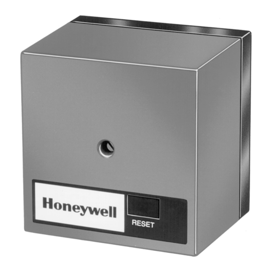
The R7795 Flame Safeguard Primary Control
provides flameout protection plus automatic
control of commercial and industrial gas and
oil burners. Models provide intermittent pilot
or interrupted pilot with delayed main valve.
Integral solid state color-coded flame amplifiers:
R7795A,C for ultraviolet detection systems (purple).
R795B,D for rectification detection systems (green).
See Table 1.
Solid state plug-in ST95A Purge Timers provide
prepurge timings of 1.5, 7, 10, 30, 60, or 90 seconds.
Includes terminals for connection of a line voltage
airflow switch to prove airflow from the start of
prepurge through the run period.
Mounts on a Q795A Subbase with two captive
screws. All electrical connections are automatically
provided between the device and subbase. Wiring
terminals are accessible for testing.
Meter jack on amplifier board for measuring flame
signal with system in operation.
Internal light-emitting diode (LED) indicates pres-
ence of flame signal.
R7795A,B,C,D
Flame Safeguard
Primary Controls
Field selectable ten or four second trial for pilot
flame ignition.
Powered alarm terminal to operate an external line
voltage alarm on safety lockout.
R7795 models are available with either intermittent
pilot (interrupted ignition) or interrupted pilot and
delayed main valve. See Table 2.
Run-Test switch on interrupted pilot/delayed main
valve models.
Safe-start feature prevents start-up with lockout if
flame or a flame simulating failure exists.
Recycle or lockout on flame failure is field selectable.
Safety switch must be manually reset after lockout.
Meets Underwriters Laboratories, Canadian Stan-
dards Association, and Factory Mutual Approved
standards.
CONTENTS
Specifications ................................................. 2
Ordering Information ..................................... 2
Detailed Operating Sequence ........................ 4
Installation ..................................................... 8
Checkout ....................................................... 11
Troubleshooting ........................................... 17
Service .......................................................... 19
B. M. • Rev. 9-93 • ©Honeywell Inc. 1993 • Form Number 66-2001-2
1
66-2001-2

Related Manuals for Honeywell R7795A


Summary of Contents for Honeywell R7795A
-
Page 1: Table Of Contents
CONTENTS Specifications ..........2 Ordering Information ........2 Detailed Operating Sequence ......4 Installation ............. 8 Checkout ............11 Troubleshooting ........... 17 Service ............19 B. M. • Rev. 9-93 • ©Honeywell Inc. 1993 • Form Number 66-2001—2 66-2001—2... -
Page 2: Specifications
If you have additional questions, need further information, or would like to comment on our products or services, please write or phone: 1. Your local Honeywell Home and Building Control Sales Office (check white pages of phone directory). 2. Home and Building Control Customer Satisfaction Honeywell Inc., 1885 Douglas Drive North... - Page 3 Voltage and Frequency: 120 Vac, (+10, -15%), 50/60 Hz. Guide No. MCCZ. Power Consumption: Canadian Standards Association certification: pending. R7795A,C: 17 VA (maximum). Factory Mutual approved: Report No. J.I. OR4A2.AF R7795B,D: 15 VA (maximum). ACCESSORIES (See Fig. 1): TERMINAL RATINGS:...
-
Page 4: Detailed Operating Sequence
5), the main valve (terminal 6) and the burner/ when the airflow switch recloses. blower motor (terminal 8) are immediately de-energized. The R7795 goes into the standby mode, terminating the operating cycle. Fig. 2—Operating sequence for the R7795A,B, with intermittent pilot. - Page 5 R7795A,B,C,D DETAILED OPERATING SEQUENCE Fig. 3—Internal schematic of the R7795A,B with intermittent pilot. BASIC DIAGRAM OF INTERRUPTED THE R7795A PILOT VALVE MAIN FUEL VALVE BURNER IGNITION MOTOR TRANSFORMER S.SW S.SW LINE VOLTAGE ALARM OPTO ISOLATOR FLAME AMPLIFIER FLAME SOLID STATE...
- Page 6 R7795A,B,C,D DETAILED OPERATING SEQUENCE Fig. 4—Operating sequence for the R7795C,D with interrupted pilot. The R7795C,D provides the following operational se- • Ten seconds if the ORANGE jumper is not clipped. quence when used with the appropriate flame detector. (See • Four seconds if the ORANGE jumper is clipped.
- Page 7 R7795A,B,C,D DETAILED OPERATING SEQUENCE Fig. 5—Internal schematic of the R7795C,D with interrupted pilot. BASIC DIAGRAM OF INTERRUPTED THE R7795C PILOT VALVE DELAYED MAIN VALVE MAIN FUEL VALVE BURNER IGNITION MOTOR TRANSFORMER S.SW S.SW LINE VOLTAGE ALARM OPTO ISOLATOR FLAME AMPLIFIER...
-
Page 8: Installation
350° F [175° C] for continuous duty and installation. up to 500° F [260° C] for intermittent use.) b. For the flame detector F leadwire, use Honeywell specification no. R1298020 or equivalent. (This wire Follow the burner manufacturer’s instructions if sup- is rated up to 400°... - Page 9 Fig. 6—Mounting dimensions of the Q795A Subbase shown in in. [mm]. 5. For ignition installations in a contaminating envi- INSTALLING THE R7795 ronment, use Honeywell specification no. R1239001 High 1. Remove the cover from the R7795. Tension Ignition Cable or equivalent. (This wire is very 2.
- Page 10 R7795A,B,C,D INSTALLATION Fig. 7—Wiring the R7795A,B with intermittent pilot. Fig. 8—Wiring the R7795C,D with interrupted pilot.
-
Page 11: Checkout
R7795. Checkout EQUIPMENT REQUIRED WARNING Voltmeter (Honeywell W136A or equivalent) with 0 to 300 Vac scale. IF FUEL ENTERS THE COMBUSTION Microammeter (Honeywell W136A or equivalent) with CHAMBER FOR MORE THAN A FEW 0 to 25 microamp range and SPL scale with damping. - Page 12 R7795 amplifier board (see Fig. 9). The minimum flame current must be an average of two microamperes for the R7795B,D models and an aver- age of 3.5 microamperes for the R7795A,C models (refer to Table 3). If the minimum average current level cannot be ob- tained, one or more of the following conditions may exist: 1.
- Page 13 R7795A,B,C,D CHECKOUT 7. Make sure that the detector is sighting the flame 8. Recycle the system to recheck lightoff and the pilot properly. flame signal. 8. If necessary, resight or reposition the flame detector. If proper operation cannot be obtained, replace the flame NOTE: The next steps require two people—one to open...
- Page 14 R7795A,B,C,D CHECKOUT INITIAL LIGHTOFF CHECK FOR DIRECT d. Make burner adjustments for flame stability and SPARK IGNITION OF OIL (Oil Burners Not input rating. Using a Pilot) e. Shut down the system by lowering the setpoint of This check applies to oil burners not using a pilot. It the burner controller.
- Page 15 R7795A,B,C,D CHECKOUT NOTE: The next step requires two people—one to open the 13. Repeat the main burner lightoff several times with manual main fuel valve(s) and one to watch for ignition. the pilot at turndown. 14. When the main burner lights reliably with the pilot at d.
- Page 16 It should not be more than one-fourth microampere. Flame Failure Let the burner operate five minutes; then manually NOTE: The Honeywell Q624A Solid State Spark Gen- shut off the fuel supply to simulate flame failure. The erator will prevent detection of ignition spark when...
-
Page 17: Troubleshooting
Meter connector plug part no. 196146 or equivalent. 123514A Flame Simulator: for use with the R7795B,D (rectification models). 123514B Flame Simulator: for use with the R7795A,C (ultraviolet models). Watch or clock: with second hand. Manometer (or gauge): to measure pilot gas pressure. - Page 18 RECTIFICATION MODELS: 2. R7795A,C (ultraviolet) models: 1. If the flame detector is a rectifying flame rod, install a a. Measure the flame current during prepurge. The new R7795. flame current should not exceed one-fourth mi- 2.
-
Page 19: Service
1. Do not clean contacts unless absolutely necessary. heating equipment or controls. 2. Use only Honeywell contact cleaner part no. 132569. 2. Check all the items required in the Checkout section DO NOT use any other type of contact cleaner. - Page 20 Home and Building Control Home and Building Control Helping You Control Your World Honeywell Inc. Honeywell Limited—Honeywell Limitée 1985 Douglas Drive North 740 Ellesmere Road Golden Valley, MN 55422 Scarborough, Ontario M1P 2V9 QUALITY IS KEY Printed in U.S.A. www.honeywell.com/bbc...