Epson RC700 Series Original Instructions Manual
Robot controller
Hide thumbs
Also See for RC700 Series:
- Manual (316 pages) ,
- Maintenance manual (90 pages) ,
- Manual (66 pages)

Related Manuals for Epson RC700 Series


Summary of Contents for Epson RC700 Series
- Page 1 ROBOT CONTROLLER RC700 Series Manual Rev.3 ENM226C5414F Original instructions Control Unit RC700 RC700-A Drive Unit RC700DU RC700DU-A...
- Page 3 ROBOT CONTROLLER RC700 Series Manual Rev.3 Seiko Epson Corporation 2021-2022 RC700 Series Rev.3...
- Page 4 Please notify us if you should find any errors in this manual or if you have any comments regarding its contents. MANUFACTURER CONTACT INFORMATION Contact information is described in “SUPPLIERS” in the first pages of the following manual: Robot System Safety Manual Read this manual first RC700 Series Rev.3...
- Page 5 For more details on available collection facilities please contact your local government office or the retailer where you purchased this product. For California customers only The lithium batteries in this product contain Perchlorate Material - special handling may apply, See www.dtsc.ca.gov/hazardouswaste/perchlorate RC700 Series Rev.3...
- Page 6 Jog Pad JP500 Teaching Pendant TP-3** Operator Panel OP1 For RC700 / RC700-A, be sure to install the EPSON RC+7.0 to the development PC first, then NOTE connect the development PC and RC700 / RC700-A with the USB cable.
- Page 7 Structure of Robot System The Drive Unit RC700DU can be used with the following version. EPSON RC+ 7.0 Ver.7.1.0 or later Control Unit RC700-A Drive Unit RC700DU-A can be used with the following version. EPSON RC+ 7.0 Ver.7.1.2 or later Each manipulator can be used with the following version.
- Page 8 This manual contains a list of code numbers displayed on the controller and messages displayed in the software message area. The manual is primarily intended for people who design robot systems or do programming. RC700 series Maintenance Manual (PDF) xx series Maintenance Manual (PDF) (xx: Manipulator series name) This manual describes the details of maintenance etc.
- Page 9 EPSON RC+ 7.0 User’s Guide (PDF) This manual describes general information about program development software. EPSON RC+ 7.0 SPEL+ Language Reference (PDF) This manual describes the robot programming language “SPEL+”. Other Manual (PDF) Manuals for each option are available. RC700 Series Rev.3...
- Page 10 RC700 Series Rev.3...
-
Page 11: Table Of Contents
2.6.11 Robot Operation Panel ............. 37 2.7 Connecting ....................37 2.7.1 Connection to EMERGENCY Connector ........37 2.7.2 Power Supply ................48 2.7.3 Connecting Control Unit and Drive Unit ........51 2.7.4 Drive Unit Setup ................52 RC700 Series Rev.3... - Page 12 3.1 Power-ON Precautions ................56 3.2 Power ON Procedure ................58 4. First Step 4.1 Installing EPSON RC+ 7.0 Software ............59 4.2 Development PC and Controller Connection ......... 61 4.2.1 About Development PC Connection USB Port ......62 4.2.2 Precaution ................... 62 4.2.3 Software Setup and Connection Check........
- Page 13 6.2 Switch Operation Mode ................ 116 6.3 Program Mode (AUTO) ................. 117 6.3.1 What is Program Mode (AUTO)? ..........117 6.3.2 Setup from EPSON RC+ ............117 6.4 Auto Mode (AUTO) ................118 6.4.1 What is Auto mode (AUTO)? ............ 118...
- Page 14 8.2.2 Adoptable USB Memory ............123 8.3 Backup Controller Function ..............124 8.3.1 Backup Controller with Trigger Button ........124 8.3.2 Load Data with EPSON RC+ 7.0 ..........124 8.3.3 Transfer with E-mail ..............124 8.4 Details of Data ..................125 9.
- Page 15 11.4.2 Circuit and Wiring for Drive Unit..........139 12. Standard RS-232C Port 12.1 RS-232C Port..................143 12.2 Confirmation with EPSON RC+ 7.0 (RS-232C) ......... 143 12.3 RS-232C Software Communication Setup (RS-232C) ...... 144 12.4 Communication Cable (RS-232C) ............144 13. I/O Connector 13.1 Input Circuit ..................
- Page 16 16.2 Expansion I/O Board ................166 16.2.1 Expansion I/O Board ............... 166 16.2.2 Board Configuration (Expansion I/O Board) ......167 16.2.3 Confirmation with EPSON RC+ 7.0 (Expansion I/O Board) ... 167 16.2.4 Input Circuit ................168 16.2.5 Output Circuit ................170 Typical Output Circuit Application 1: Sink Type (NPN) ......
- Page 17 16.8.1 Notes on the EUROMAP67 Board .......... 192 16.8.2 Board Settings (EUROMAP67 Board) ........193 16.8.3 Installation (EUROMAP67 Board) .......... 193 16.8.4 Confirming with EPSON RC+ 7.0 (EUROMAP67 Board)..194 16.8.5 Sample Project (EUROMAP67 Board) ........194 16.8.6 Circuit Overview (EUROMAP67 Board) ......... 195 16.8.7 Input Circuit (EUROMAP67 Board) ........
- Page 18 Table of Contents RC700 Series Rev.3...
-
Page 19: Installation
Installation This section describes outline from unpacking to operation of Robot System and design of Robot System. -
Page 21: Safety
WARNING not followed properly. This symbol indicates that a danger of possible harm to people or physical damage to equipment and facilities exists if the associated CAUTION instructions are not followed properly. RC700 Series Rev.3... -
Page 22: Installation
RS-232C Board USB2.0 or Ethernet RC700DU/ Standard RC700DU-A Standard I/O Remote I/O Ethernet RS-232C C4 series C8 series C12 series Windows *1 series TP1 (Option) series EPSON RC+ 7.0 software Option Requires preparation by uses (Option) TP3 (Option) RC700 Series Rev.3... -
Page 23: Unpacking
Installation 2. Installation *1 EPSON RC+ 7.0 supports the following OS. Windows 8.1 Pro (EPSON RC+ 7.0 Ver.7.1.0 or later Windows 10 Pro (EPSON RC+ 7.0 Ver.7.2.0 or later *2 Up to three drive unit can be connected. *3 Any one of the manipulators can be controlled. -
Page 24: Number Of People And Position To Hold, When Transporting Manipulator
: Under the arm 1 and bottom of the base *(shade part) * When hold bottom of the base, be careful not caught your hands or fingers. Minimum number of people : 2 people Do not hold RC700 Series Rev.3... - Page 25 Where to hold : Under the arm 1 and bottom of the base *(shade part) When hold bottom of the base, be careful not caught your hands or fingers. Minimum number of people : 2 people Do not hold RC700 Series Rev.3...
- Page 26 : Bottom of the base (slashed part) Where to hold : The part other than the part that is should not touch Minimum number of people : 2 people Do not hold : Bottom of the base (slashed part) Figure: C8-A901* (C8L) RC700 Series Rev.3...
- Page 27 Where to hold : Under the arm and bottom of the base * * When hold bottom of the base, be careful not caught your hands or fingers. Minimum number of people : 2 people Do not hold RC700 Series Rev.3...
-
Page 28: Manipulator Installation
10 minutes. NOTE Manipulators are not suitable for operation in harsh environments such as painting areas, etc. When using Manipulators in inadequate environments that do not meet the above conditions, please contact the supplier of your region. RC700 Series Rev.3... -
Page 29: Noise Level
When using a leveler to adjust the height of the base table, use a screw with M16 diameter. The torque and reaction force produced by Manipulator motion are as follows: RC700 Series Rev.3... - Page 30 The surface roughness of the steel plate should be 25 μm or less. C12 Series C12-A1401** Max. Reaction torque on 2600 the horizontal plate (N·m) Max. Horizontal reaction 1000 force (N) Max. Vertical reaction 3400 force (N) Threaded holes for 7900 Mounting screw RC700 Series Rev.3...
- Page 31 (N·m) The plate for the Manipulator mounting face should be 30 mm thick or more and made of steel to reduce vibration. The surface roughness of the steel plate should be 25 μm or less. RC700 Series Rev.3...
-
Page 32: Installation Procedure
Use M6 mounting bolts (screw hole depth: 25 mm + Spring washer + Plane washer) conforming to the strength, ISO898-1 property class: 6.9. Tightening torque: 13 N·m (133 kgf·cm) G1-177* 8kg: 18 lbs. G1-221* 8kg: 18 lbs. RC700 Series Rev.3... - Page 33 (2) Using nippers, cut off the wire tie binding the shaft and arm retaining bracket on the base. (3) Remove the bolts securing the wire ties removed in step (2). Wire tie (4) Remove the shipping bolt and jigs. Bolt: M4×15 Sheet RC700 Series Rev.3...
- Page 34 (depth 20 mm or more) Use bolts with specifications conforming to NOTE ISO898-1 Property Class: 10.9 or 12.9. Tightening torque : 32.0 N·m (326 kgf·cm) Pane Washer Spring Washer 4-M8×30 (3) Remove the shipping bolt and jigs. RC700 Series Rev.3...
- Page 35 (2) Using nippers, cut off the wire tie binding the shaft and arm retaining bracket on the base. (3) Remove the bolts securing the wire ties Bolt : M4×15 removed in step (2). Sheet Wire tie (4) Remove the shipping bolt and jigs. Bolt : M5×15 RC700 Series Rev.3...
- Page 36 Use bolts with specifications conforming to NOTE (depth 20 mm or more) ISO898-1 Property Class: 10.9 or 12.9. Tightening torque : 32.0 N·m (326 kgf·cm) Pane Washer (3) Remove the shipping bolt and jigs. Spring Washer 6-M8×4 RC700 Series Rev.3...
- Page 37 (depth 20 mm or more) NOTE Use bolts with specifications conforming to ISO898-1 Property Class: 10.9 or 12.9. Pane Washer Tightening torque Spring Washer : 32.0 N·m (326 kgf·cm) 4-M8×4 (3) Remove the shipping bolt and jigs. RC700 Series Rev.3...
- Page 38 Washer : M6 base. Wire tie (3) Remove the bolts securing the wire ties removed in step (2). Arm mounting bolt : M12×20 (4) Remove the shipping bolt and jigs. Eyebolt (Attached at shipment) RC700 Series Rev.3...
- Page 39 Use bolts with specifications conforming to NOTE ISO898-1 Property Class: 10.9 or 12.9. Tightening torque Screw Hole : 32.0 N·m (326 kgf·cm) (depth 20 mm or more) Pane washer (3) Remove the shipping bolt and jigs. 6-M12×40 Spring Washer RC700 Series Rev.3...
- Page 40 (depth 20 mm or more) Use bolts with specifications conforming to NOTE ISO898-1 Property Class: 10.9 or 12.9. Pane Washer Spring Washer Tightening torque 4-M12×40 : 32.0 N·m (326 kgf·cm) (3) Remove the shipping bolt and jigs. RC700 Series Rev.3...
- Page 41 Screw Hole NOTE Intensity of the bolts should be equivalent to (depth 12 mm ISO898-1 Property Class 10.9 or 12.9. or more) Tightening torque : 13.0 N·m (133 kgf·cm) (3) Remove the shipping bolt and jigs. 6-M6×20 RC700 Series Rev.3...
- Page 42 It is recommended that the core size of the grounding wire be 5.5 mm2 or more. Directly connect the ground line to the Manipulator as shown in the figure below. Bolt hole M5 (for grounding) 5.5 mm or more Detail of A RC700 Series Rev.3...
- Page 43 (depth 25 mm or more) 100 N·m (1020 kgf·cm) After installing the robot, make sure 4-M4×8 to remove the fixing jig that fix the base and the Arm #1. Hexagon socket head screws: 4-M4×8 Fixing jig for transportation RC700 Series Rev.3...
- Page 44 It is recommended that the core size of the grounding wire be 5.5 mm2 or more. Directly connect the ground line to the Manipulator as shown in the figure below. N6-A1000** Bolt hole M5 (for grounding) N6-A850**R Bolt hole M5 (for grounding) RC700 Series Rev.3...
-
Page 45: Control Unit And Drive Unit Installation
- Keep away from dust, oily mist, oil, salinity, metal powder or other contaminants. - Keep away from water. - Keep away from shocks or vibrations. - Keep away from sources of electronic noise - Keep away from strong electric or magnetic fields. RC700 Series Rev.3... -
Page 46: Installation
M4×8. (C) Rack mounting * A plate for rack mounting is required. NOTE For Control Unit and Drive Unit installation to the Controller box or the base table, process screw hole drilling as follows. RC700 Series Rev.3... - Page 47 - Hot air with higher temperature than the ambient temperature (about 10 °C) comes out from the Controller. Make sure that heat sensitive devices are not placed near the outlet. - Arrange the cables in front of the Controller so that you can pull the Controller forward. RC700 Series Rev.3...
-
Page 48: Wall Mounting Option
2.5.3 Wall Mounting Option The control unit and drive unit have a wall mounting option. For the procedure about installation, refer to RC700 Series Maintenance Manual. Controller outer dimensions when using the wall mounting option Dimensions of the mounting holes for the wall... -
Page 49: Designing A Safe Robot System
This section summarizes the minimum conditions that should be observed when using EPSON robots in your robot systems. Please design and manufacture robot systems in accordance with the principles described in this and the following sections. -
Page 50: Disabling Power To The System Using Lock Out / Tag Out
Design the size of the end effector with care, since the robot body and robot end effector can interfere with each other. RC700 Series Rev.3... -
Page 51: Peripheral Equipment Design
In many cases, the stop position will not exceed the target position for the operation prior the emergency stop. Depending on the robot’s loading condition and operation speed, overruns are inevitable. Taking this into consideration, be sure the layout for the peripheral equipment includes extra space. RC700 Series Rev.3... - Page 52 Pause and STOP commands do not turn OFF the motors. Therefore, the brake does not function. For the Safeguard system, do not use the circuit for E-STOP. To check brake problems, refer to the following manuals. Manipulator Manual Inspection Point 1.1.2 Inspection Item RC700 Series Rev.3...
-
Page 53: Safeguard
It is dangerous to allow someone else to release the safeguard interlock by mistake while the operator is working inside the safeguarded area. To protect the operator working inside the safeguarded area, take measures to lock out and tag out the latch-release switch. RC700 Series Rev.3... -
Page 54: Presence Sensing Device
If the robot stops operating when the presence sensing device is activated, it is necessary to ensure that it does not start again until the detected object has been removed. Make sure that the robot cannot automatically restart. RC700 Series Rev.3... -
Page 55: Resetting The Safeguard
The EMERGENCY connector has input terminals for the Safety Door switch and the Emergency Stop switch. Be sure to use these input terminals to keep the system safe. Connector Standard EMERGENCY connector D-sub25 Pin (male) (Controller side) Screwlock #4-40 RC700 Series Rev.3... - Page 56 When the latched TEACH mode is released while the safety door is open, the status of NOTE Manipulator power is operation-prohibited because the safety door is open at that time. To execute a Manipulator operation, close the safety door again, and then close the latch release input. RC700 Series Rev.3...
- Page 57 (1) Turn ON the Controller while the safety door is open in order to boot the Controller software. (2) Make sure that “Safety” is displayed on the EPSON RC+ 7.0 status bar. (3) Close the safety door, and turn ON the switch connecting to the latch release input.
- Page 58 (1) Turn ON the Controller to boot the software while pressing the Emergency Stop switch. (2) Make sure that “ERROR/E-STOP” LED on Drive Unit has been turned ON. (3) Make sure that “EStop” is displayed on the status bar on the EPSON RC+ main window. (4) Release the Emergency Stop Switch.
- Page 59 The 24 V output is for emergency stop. Do not use it for other purposes. Doing so may result in system malfunction. ■ Do not apply reverse voltage to the Emergency Stop circuit. CAUTION Doing so may result in system malfunction. RC700 Series Rev.3...
- Page 60 Motor Driver ESTOP1− AC Input ESTOP2− Emergency Stop detection External +24V Safety Door input 1 Safety Door input 2 Latch release input NOTE:+24V GND + 5V GND Latch release input External Close: Latch off +24V Open: Latch on RC700 Series Rev.3...
- Page 61 - 0.4A or less AC Input Emergency Stop detection Exeterks+24V External +24V Safety Door input 1 Safety Door input 2 Latch Release input External Latch release input +24V NOTE:+24V GND + 5V GND Close: Latch off Open: Latch on RC700 Series Rev.3...
- Page 62 Circuit Diagrams – Drive unit Circuit Diagram Drive unit ESTOP1+ ESTOP2+ Main Circuit Control Be careful of the direction of voltage application ESTOP1− ESTOP2− Emergency Stop detection Safety Door input 1 Safety Door input 2 Latch release input RC700 Series Rev.3...
- Page 63 Emergency stop switch of an Operation Unit (TP) Terminal block NOTE The Emergency cable, Emergency cable kit, and Terminal block are offered as options. Design the cables connecting the units within 20 m long. RC700 Series Rev.3...
- Page 64 +24V External +24V External +24V External +24V Terminal block * Fuse For the protection of the emergency stop circuit, the fuse’s capacity should be as follows: - Meets the capacity of the external - 0.4A or less RC700 Series Rev.3...
- Page 65 Latch release input Safety Door input 1 Safety Door input 2 Latch release input Safety Door input 1 Safety Door input 2 Latch release input External NOTE Design the cables connecting the units within 20 m long. RC700 Series Rev.3...
-
Page 66: Power Supply
RC700DU / RC700DU-A : 8.5 A : 12.5 A : 11.0 A : 2.5 A : 5.5 A : 7.5 A G10 : 12.0 A G20 : 12.0 A RS3 : 6.0 A RS4 : 7.0 A RC700 Series Rev.3... - Page 67 10 kHz or more leakage current. If you install a circuit breaker, please select one that will handle the above mentioned “inrush current”. The power receptacle should be installed near the equipment and should be easily accessible. RC700 Series Rev.3...
- Page 68 Following shows specification of power connection side. Mount to the plug like following below. Item Specification AC power wire Black, Black (2 cables) Ground wire Green / Yellow Cable length M4 round solderless Terminal terminal RC700 Series Rev.3...
-
Page 69: Connecting Control Unit And Drive Unit
Do not use any LAN cables on the market. Otherwise, it results in the Robot Controller malfunction. How to turn ON the power switch: Check the connection first. Then, make sure to turn ON the power switch of Drive Unit before turning ON the power switch of Control Unit. RC700 Series Rev.3... -
Page 70: Drive Unit Setup
1 2 3 4 (3) Attach the DU number label on Drive Unit. DU1 : 1 Drive Unit DU2 : 2 Drive Unit DU3 : 3 Drive Unit (4) Plug in the power connector. Turn ON the Drive Unit. RC700 Series Rev.3... - Page 71 The Manipulator without connecting them may result in electric shock and/or malfunction of the robot system as it cannot ensure IP65. Connect the power connector and the signal connector of the M/C cables to the Controller. RC700 Series Rev.3...
- Page 72 Install the Control Unit and Drive Unit, and then turn ON the robot system. After turning ON the system, add information of the additional system. (1) Select the EPSON RC+ 7.0-[Setup]-[System Configuration]. [System Configuration] dialog box will appear. (2) Click [Controller]-[Robots] in the tree on the left.
-
Page 73
All Manipulators available for the motor driver currently installed in the Controller will be displayed. (5) Click the
button. The EPSON RC+ will restart. (6) Click [Controller]-[Robots]-[Robot **]-[Calibration] in the tree on the left. Following dialog box will appear. - Page 74 1. Brake release unit (option) 2. External short connector When operating the Manipulator, be sure to connect either of the parts to the position indicated below. C4, C8, C12 (Figure: The external short connector is connected C4) RC700 Series Rev.3...
- Page 75 ■ When connecting or replacing the parts, turn OFF the power to the Controller and the brake release unit. Inserting and removing the WARNING connector while the power is ON may result in electrical shock. RC700 Series Rev.3...
- Page 76 Control unit starts up normally. If an error is displayed, check connection in step (1) to (5) and turn ON the power again. If an error is displayed after checking the connection, contact the supplier in your region. RC700 Series Rev.3...
- Page 77 Installation 4. First Step 4. First Step This section indicates the procedure to install the development PC EPSON RC+, and execute simple program after connecting the development PC and Controller with a USB. Make sure that the Robot system is installed safely by following the description in “Safety”...
-
Page 78
Installation 4. First Step (4) Select the drive where you want to install EPSON RC+ 7.0 and click
. The installation directory is called EpsonRC70. This cannot be changed. (5) The dialog box for selecting the options to be installed will be displayed. Check the options you want to install and click . - Page 79 - For other details of development PC and Controller connection, refer to EPSON RC+7.0 User’s Guide: [PC to Controller Communications] Command (Setup Menu). - For RC700 / RC700-A, be sure to install the EPSON RC+7.0 to the development PC first, then connect the development PC and RC700 / RC700-A with the USB cable.
- Page 80 (USB Ver.1.1 upward compatible) Connect the Controller and development PC by a USB cable to develop the robot system or set the Controller configuration with the EPSON RC+ 7.0 software installed in the development PC. Development PC connection port supports hot plugging. Insertion and removal of the cables while the power of the development PC and the Controller are ON is available.
- Page 81 4.2.3 Software Setup and Connection Check The following is the steps of connecting the development PC and the Controller. (1) Make sure that EPSON RC+ 7.0 is installed on the Controller connected to the development PC. (Install the software when it is not installed.) (2) Connect the development PC and the Controller by the USB cable.
-
Page 82
4.2.5 Disconnection of Development PC and Controller Disconnection of the development PC and the Controller is indicated. (1) Select the EPSON RC+ 7.0 menu-[Setup]-[PC to Controller Communications] to display the [PC to Controller Communications] dialog box. (2) Click the
button. -
Page 83
The arm falling may cause equipment damage to and/or malfunction of the Manipulator. (1) Start the EPSON RC+ 7.0. Double click the
icon on the desktop. (2) Open the command window. EPSON RC+ 7.0 menu-[Tool]-[Command Window] (3) Execute the following command in [Command Window]. -
Page 84
(1) Start EPSON RC+ 7.0. Double click the
icon on the desktop. (2) Create a new project. 1. EPSON RC+ 7.0 menu-[Project]-[New Project]. [New Project] dialog box will be displayed. 2. Enter the project name in [Project Name] box. (Ex: FirstApp) 3. -
Page 85
(5) Move the Manipulator with Jog motion. Select [Jog & Teach] tab. Select “Joint” in [Jogging]-
. Move the Manipulator by joint by clicking J1-J6 jog keys. Manipulator can be moved by setting to other modes or setting the jog distance. RC700 Series Rev.3... - Page 86 Installation 4. First Step 4.3 Writing your first program After installing the Controller, Manipulator, and EPSON RC+ 7.0 software on your PC, follow the instructions below to create a simple application program so that you will become more familiar with EPSON RC+ 7.0 development environment.
- Page 87 (3) Click the Start button on the Run window to run the program. (4) The texts like the following will be displayed in the status window. 19:32:45 Task main started 19:32:45 All tasks stopped On the Run window, you will see the output of the print statement. RC700 Series Rev.3...
-
Page 88
(7) Click the <-Z> button to lower the Z axis of the robot. (8) Select “P1” in the [Point (P)] dropdown list which is next to the
button. The current point is set to P1. RC700 Series Rev.3... -
Page 89
(3) Click the
button to execute the program. (4) The robot will move to each of the points you taught at 20% speed, acceleration, and deceleration. The Power High statement executes the program to operate the robot with increased speed and acceleration. RC700 Series Rev.3... - Page 90 Even though this is only a sample project, we will backup the project and Controller configuration. Backup can be done easily with EPSON RC+ 7.0. It is important that you keep regular backups of your applications on an external media such as a USB memory key.
- Page 91 5.1 Connection with External Equipment 5.1.1 Remote Control EPSON RC+ 7.0 User’s Guide 12. Remote Control “12.1 Remote I/O” EPSON RC+ 7.0 User’s Guide 11. Inputs and Outputs RC700 series manual “13. I/O Connector” “16.2 Expansion I/O Board” Fieldbus I/O (Option) Robot Controller Option Fieldbus I/O Board 5.1.2 Ethernet...
- Page 92 Installation 5. Second Step 5.2 Ethernet Connection of Development PC and Controller EPSON RC+ 7.0 User’s Guide “1.9 Security for Controller Ethernet Connection” “1.10 Security for Compact Vision CV2-A Ethernet Connection” “1.11 Security for Feeder Ethernet Connection” “4.3.3 Ethernet Communication”...
- Page 93 Functions required for designing This section contains information for setup and operation of the Robot Controller and Drive Unit.
- Page 95 RS-232C Board USB2.0 or Ethernet RC700DU/ Standard RC700DU-A Standard I/O Remote I/O Ethernet RS-232C C4 series C8 series C12 series Windows *1 series TP1 (Option) series EPSON RC+ 7.0 software Option Requires preparation by uses (Option) TP3 (Option) RC700 Series Rev.3...
- Page 96 Functions 1. Specifications *1 EPSON RC+ 7.0 supports the following OS. Windows 8.1 Pro (EPSON RC+ 7.0 Ver.7.1.0 or later Windows 10 Pro (EPSON RC+ 7.0 Ver.7.2.0 or later *2 Up to three drive unit can be connected. *3 Any one of the manipulators can be controlled.
- Page 97 Output : 16 Unit Output : 16 input/output Assignment signals (standard) change allowed Input : 2 R I/O Output : 2 Communication Ethernet 1 channel interface (standard) Drive Unit connect 2 channel interface (standard) RS-232C port 1 port RC700 Series Rev.3...
- Page 98 - Overheat detection at the Motor Driver Module - Relay welding detection - Over-voltage detection - AC power supply voltage reduction detection - Temperature error detection - Fan error detection 200 VAC to 240 VAC Power Source Single phase 50/60 Hz RC700 Series Rev.3...
- Page 99 *2 When using the Force Sensor I/F board, a maximum of one board/two ports expansion is available for RS-232C board. NOTE Use this product under the condition of overvoltage category 2, degree of stain category 2. RC700 Series Rev.3...
- Page 100 Functions 1. Specifications 1.3 Outer Dimensions Outer Dimensions of Control Unit [Unit: mm] (Figure: RC700) RC700 Series Rev.3...
- Page 101 Functions 1. Specifications Outer Dimensions of Drive Unit [Unit: mm] RC700 Series Rev.3...
- Page 102 Check the condition of the filter regularly and clean it when necessary. A dirty filter may result in malfunction of the robot system due to temperature rise of the Drive Unit. For inspection, cleaning, and replacement, refer to the Maintenance 4.1 Fan Filter, 4.2 Fan. RC700 Series Rev.3...
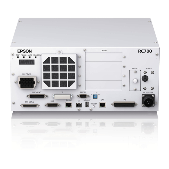
- Page 103 (14) M/C SIGNAL connector This connector is used for signals such as the Manipulator’s motor encoders, etc. Connect the Manipulator’s dedicated signal cable. (15) R-I/O connector This connector is for the input signals used for the real time I/O function. RC700 Series Rev.3...
- Page 104 For details, refer to Setup & Operation 13. I/O Connector. (22) AC IN The connector for 200VAC power input. For details, refer to 3.3.2 AC Power Cable. (23) Control Unit Signature label The serial number of the Control Unit and other information are shown. RC700 Series Rev.3...
- Page 105 (3) Set the screw removed in the step (1) to the lockout bracket B so as not to lose it. (4) Put a padlock through the holes of the lockout brackets A and B to lock. Padlock RC700 Series Rev.3...
- Page 106 Check the condition of the filter regularly and clean it when necessary. A dirty filter may result in malfunction of the robot system due to temperature rise of the Drive Unit. For inspection, cleaning, and replacement, refer to RC700 series Maintenance Manual 4.1 Fan Filter, 4.2 Fan.
- Page 107 For details, refer to 13. I/O Connector. (15) AC IN The cable for 200VAC power input. For details, refer to 3.3.2 AC Power Cable. (16) Drive Unit Number label The serial number of the Drive Unit is indicated. RC700 Series Rev.3...
- Page 108 PAUSE Blink line number *1 For error numbers, refer to EPSON RC+ 7.0 SPEL+ Language Reference, or Online Help. *2 In initial status, execution line of task number 1 is displayed in three-digit. Use Ton statement to change the displayed task number.
- Page 109 Teach mode Robot error Flashing Flashing rapidly Emergency stop Flashing rapidly The error information is displayed on the seven-segment display of the Control Unit. NOTE For details, refer to the 2.1 LED and Seven-segment LED Controller. RC700 Series Rev.3...
- Page 110 Controller status Controller startup failure *1 Controller startup failure Indicate:9999 Controller in Recovery mode Refer to RC700 series Maintenance Manual 4. Backup and Restore. Indicate:9998 AC power supply drop is detected and software shut down. Indicate:9997 Software shut down is specified from the EPSON RC+ 7.0 (software) or the Teach Pendant (option).
- Page 111 CPU and the motor controlling CPU inside the Drive Unit are also designed to constantly check each other for any discrepancies. If a discrepancy is detected, the dynamic brake circuit is activated. Memory Check-sum Error Detection The dynamic brake circuit is activated when a memory check-sum error is detected. RC700 Series Rev.3...
- Page 112 AC Power Supply Voltage Drop Detection The dynamic brake circuit is activated when the drop of the power supply voltage is detected. Temperature Anomaly Detection The temperature anomaly is detected. Fan Malfunction Detection Malfunction of the fan rotation speed is detected. RC700 Series Rev.3...
- Page 113 Rack-Mount Plate 1 set Power Cable 1 cable USB Cable Clamp 1 set Drive Unit EMERGENCY port connector 1 set I/O Connector 1 set Rack-Mount Plate 1 set Power Cable 1 cable Connecting cable for RC700DU 1 cable RC700 Series Rev.3...
- Page 114 - Keep away from dust, oily mist, oil, salinity, metal powder or other contaminants. - Keep away from water. - Keep away from shocks or vibrations. - Keep away from sources of electronic noise - Keep away from strong electric or magnetic fields. RC700 Series Rev.3...
- Page 115 Ensure the air flow around the supply and exhaust ports, and install the Controller while leaving space from other equipment or walls as below. * Keep the space about 200 mm or more on the top to maintenance. RC700 Series Rev.3...
- Page 116 - Hot air with higher temperature than the ambient temperature (about 10 °C) comes out from the Controller. Make sure that heat sensitive devices are not placed near the outlet. - Arrange the cables in front of the Controller so that you can pull the Controller forward. RC700 Series Rev.3...
- Page 117 Functions 3. Installation 3.2.3 Wall Mounting Option The controller has a wall mounting option. For the procedure about installation, refer to RC700 Series Maintenance Manual. Controller outer dimensions when using the wall mounting option Dimensions of the mounting holes for the wall...
- Page 118 : 2.5 kVA : 2.2 kVA : 0.5 kVA : 1.1 kVA : 1.5 kVA : 2.4 kVA : 2.4 kVA : 1.2 kVA : 1.4 kVA Refer to the Manipulator manual for rated capacity of the Manipulator motor. RC700 Series Rev.3...
- Page 119 10 kHz or more leakage current. If you install a circuit breaker, please select one that will handle the above mentioned “inrush current”. The power receptacle shall be installed near the equipment and shall be easily accessible. RC700 Series Rev.3...
- Page 120 Make sure to insert the plug of the AC power cable firmly when connecting to the Controller. Following shows specification of power connection side. Mount to the plug like following below. Item Specification AC power wire Black, Black (2 cables) Ground wire Green / Yellow Cable length M4 round solderless Terminal terminal RC700 Series Rev.3...
- Page 121 Manipulator may cause not only improper function of the robot system but also safety problems. CAUTION Before connecting the connector, make sure that the pins are not bent. Connecting with the pins bent may damage the connector and result in malfunction of the robot system. RC700 Series Rev.3...
- Page 122 Connect the Manipulator and the M/C SIGNAL connector on the Controller. (4) EMERGENCY The EMERGENCY connector has inputs to connect the Emergency Stop switch and the Safety Door switch. For safety reasons, connect proper switches for these input devices. For details, refer to the 11. EMERGENCY. RC700 Series Rev.3...
- Page 123 This connector is used for connecting with input signals necessary for real time I/O function. For details, refer to the 15. R-I/O Connector. (12) Fieldbus I/O If necessary, take EMC countermeasures for the Fieldbus I/O cable. For details, refer to 3.5 Noise Countermeasures. RC700 Series Rev.3...
- Page 124 (2) M/C Power Cable Manipulator (3) M/C Signal Cable (4) EMERGENCY Emergency Stop Safety Door, etc. Drive Unit (5) I/O connector Input/Output (6) R-I/O connector Input/Output (7) DU IN connector Drive Unit (8) DU OUT connector (Do not connect anything.) RC700 Series Rev.3...
- Page 125 Drive Unit. * Be sure not to connect anything to this connector when using only one Drive Unit. Also, when using the 3 Drive Unit, do not connect anything to this connector on the 2 Drive Unit. RC700 Series Rev.3...
- Page 126 Therefore, the Controller should be connected to the Manipulator whose serial number is specified in the Connection Check label attached on the front of the Controller. NOTE The Manipulator’s serial number is indicated on the signature label on the back of the Manipulator. RC700 Series Rev.3...
- Page 127 The spark suppressor is more effective when placed closer to the motor. - As they are easily influenced by noise, keep cable such as USB, Ethernet, RS-232C, or fieldbus away from peripheral noise sources. RC700 Series Rev.3...
- Page 128 - Put together the cable shield side. Remove the outer cover and fix with the FG clamp. Secure the clamps to the Controller with screws to ground the shield. - Mount Ferrite core to the cable. Ferrite core RC700 Series Rev.3...
- Page 129 Do not use any LAN cables on the market. Otherwise, it results in the Robot Controller malfunction. How to turn ON the power switch: Check the connection first. Then, make sure to turn ON the power switch of Drive Unit before turning ON the power switch of Control Unit. RC700 Series Rev.3...
- Page 130 1 2 3 4 (3) Attach the DU number label on Drive Unit. DU1 : 1 Drive Unit DU2 : 2 Drive Unit DU3 : 3 Drive Unit Plug in the power connector. Turn ON the Drive Unit. RC700 Series Rev.3...
- Page 131 Set up the Control Unit and Drive Unit and turn on the robot system. If information of the new system was not added, follow the steps below to add information. (1) Select the EPSON RC+ 7.0-[Setup]-[System Configuration]. [System Configuration] dialog box will appear.
-
Page 132
All Manipulators available for the motor driver currently installed in the Drive Unit will be displayed. (5) Click
button. The EPSON RC+ will restart. (6) Click [Controller]-[Robots]-[Robot **]-[Calibration] in the tree on the left. Following dialog box will appear. - Page 133 To use a low speed program verification function (T1: manual deceleration mode) or a high speed program verification function (T2: manual deceleration mode) which is defined in Safety Standards, you will need a Teach Pendant that supported for the function. RC700 Series Rev.3...
- Page 134 If you switch the mode with the mode selector key switch and turn on the motor while the enable switch is ON, an error will occur. Turn the Enable Switch off and then on again, and then turn on the motor. RC700 Series Rev.3...
- Page 135 Follow the procedures below to switch to the Program mode. 6.3.2 Setup from EPSON RC+ Switch the mode to Program mode from the EPSON RC+. (1) Select EPSON RC+ menu-[Setup]-[System Configuration] to display the [System Configuration] dialog. (2) Select [Startup]-[Start mode].
-
Page 136: Setup From Epson Rc
Auto mode (AUTO) is for automatic operation of the Robot system. Procedures for switching to the Auto mode (AUTO) are the followings. A : Set the start mode of the EPSON RC+ to “Auto” and start the EPSON RC+. (Refer to 6.4.2 Setup from EPSON RC+.) B : Offline the EPSON RC+. -
Page 137: Setup From Control Device
Functions 6. Operation Mode (TEACH/AUTO/TEST) 6.4.3 Setup from Control Device Set the control device from EPSON RC+. (1) Select EPSON RC+ menu-[Setup]-[System Configuration] to display the [System Configuration] dialog. (2) Select [Controller]-[Configuration]. (3) Select [Setup Controller]-[Control Device] to select the control device from the following two types. -
Page 138: Development Pc Connection Usb Port
7.0 User’s Guide 5.12.1 PC to Controller Communications Command. For RC700 / RC700-A, be sure to install the EPSON RC+ 7.0 to the development PC first, then connect the development PC and RC700 / RC700-A with the USB cable. -
Page 139: Precaution
Development PC Connection USB Port Connection of the development PC and the Controller is indicated. (1) Make sure that software EPSON RC+ 7.0 is installed to the Controller connected to the development PC. (Install the software when it is not installed.) (2) Connect the development PC and the Controller using a USB cable. -
Page 140: Disconnection Of Development Pc And Controller
7.4 Disconnection of Development PC and Controller This section describes how to disconnect the development PC and the Controller communication. (1) Select the EPSON RC+ 7.0 menu-[Setup]-[PC to Controller Communications] to display the [PC to Controller Communications] dialog. (2) Click thebutton. -
Page 141: Memory Port
This function saves various kinds of Controller data to the USB memory with one push. Data saved in the USB memory is loaded to EPSON RC+ 7.0 to get the status of the Controller and the program simply and accurately. -
Page 142: Backup Controller Function
(3) Compress the folders checked in Step (2), then send them by e-mail. - Delete files that do not relate to the project before transfer. NOTE - This function is used to send the data to the system director and EPSON from the end users for problem analysis. RC700 Series Rev.3... -
Page 143: Details Of Data
VXDWORK.bin Saves information of Queues information of WorkQueues.dat WorkQue information the WorkQue. Project Select EPSON RC+ 7.0 menu-[Setup]- All files related to project except [System Configuration] to display the ProjectName.obj *1 [System Configuration] dialog. When [Include project files when status... -
Page 144: Lan (Ethernet Communication) Port
Functions 9. LAN (Ethernet Communication) Port 9. LAN (Ethernet Communication) Port - Refer to EPSON RC+ 7.0 User’s Guide 5.12.1 PC to Controller Communications NOTE Command (Setup Menu) for other details for the development PC and Controller connection. - For Ethernet (TCP/IP) communication with robot application software, refer to EPSON RC+ 7.0 Online Help or User’s Guide 14. -
Page 145: Ip Address
(1) Connect between the development PC and the Controller using the USB cable by referring to 7. Development PC Connection USB Port. (2) Select the EPSON RC+ 7.0 menu-[Setup]-[Controller] to display the following dialog. (3) Select [Controller]-[Configuration]. (4) Enter the proper IP address and subnet mask and click thebutton. -
Page 146: Connection Of Development Pc And Controller With Ethernet
(1) Connect the development PC and the Controller using the Ethernet cable. (2) Turn ON the Controller. (3) Start EPSON RC+ 7.0. (4) Display the [PC to Controller Communication] dialog from [Setup] in EPSON RC+ 7.0 menu. (5) Click thebutton. -
Page 147: Disconnection Of Development Pc And Controller With Ethernet
button to close the [PC to Controller Communications] dialog. Connection between the development PC and the Controller is complete. Now the robot system can be used via an Ethernet connection from EPSON RC+ 7.0. 9.5 Disconnection of Development PC and Controller with Ethernet Disconnection of the development PC and the Controller is shown below. -
Page 148: Tp Port
OPTIONAL DEVICE dummy plug Operation Pendant OP500 Operator Pendant OP500RC Jog Pad JP500 Teaching Pendant TP-3** Operator Panel OP1 Extended Enable cannot be connected. Use the Enable comes with the TP. RC700 Series Rev.3... -
Page 149: Teach Pendant Connection
For details, refer to the following manuals: Robot Controller Option Teach Pendant TP1 Robot Controller Option Teach Pendant TP2 Robot Controller Option Teach Pendant TP3 External enable switch cannot be connected to the TP port. Use the enable switch provided with the TP. RC700 Series Rev.3... -
Page 150: Emergency
Before connecting the connector, make sure that the pins are not bent. Connecting with the pins bent may damage the connector and result in malfunction of the robot system. CAUTION Control Unit EMERGENCY Connector (Figure: RC700) Drive Unit EMERGENCY Connector RC700 Series Rev.3... -
Page 151: Safety Door Switch And Latch Release Switch
EMERGENCY connector on the Controller. - The Safety Door must be designed and installed so that it does not close accidentally. RC700 Series Rev.3... -
Page 152: Latch Release Switch
The latch release input also functions to acknowledge the change of to TEACH mode. NOTE In order to change the latched condition of TEACH mode, turn the mode selector key switch on the Teach Pendant to “Auto”. Then, close the latch release input. RC700 Series Rev.3... -
Page 153: Emergency Stop Switch Connection
To recover from the emergency stop condition, follow the procedure of safety check as required by the system. After safety check, the operations below are required to recover from the emergency stop condition. - Release the Emergency Stop Switch - Execute the RESET command RC700 Series Rev.3... -
Page 154: Pin Assignments
The 24 V output is for emergency stop. Do not use it for other purposes. Doing so may result in system malfunction. Do not apply reverse voltage to the Emergency Stop circuit. Doing so may result CAUTION in system malfunction. RC700 Series Rev.3... -
Page 155: Circuit Diagrams
Motor Driver ESTOP1− AC Input ESTOP2− Emergency Stop detection External +24V Safety Door input 1 Safety Door input 2 Latch release input External +24V Latch release input Close :Latch off NOTE:+24V GND Open :Latch on + 5V GND RC700 Series Rev.3... - Page 156 - 0.4A or less AC Input Emergency Stop detection External +24V External +24V Safety Door input 1 Safety Door input 2 Latch Release input External +24V Latch release input Close :Latch off NOTE:+24V GND Open :Latch on + 5V GND RC700 Series Rev.3...
-
Page 157: Circuit And Wiring For Drive Unit
11.4.2 Circuit and Wiring for Drive Unit Circuit Diagram Drive Unit ESTOP1+ ESTOP2+ Main Circuit Control Be careful of the direction of voltage application ESTOP1− ESTOP2− Emergency Stop detection Safety Door input 1 Safety Door input 2 Latch release input RC700 Series Rev.3... - Page 158 Emergency stop switch Emergency Stop switch of an Operation Unit (TP) Terminal block NOTE The Emergency cable, Emergency cable kit, and Terminal block are offered as options. Design the cables connecting the units within 20 m long. RC700 Series Rev.3...
- Page 159 +24V External +24V External +24V External +24V Terminal block * Fuse For the protection of the emergency stop circuit, the fuse’s capacity should be as follows: - Meets the capacity of the external - 0.4A or less RC700 Series Rev.3...
- Page 160 Latch release input Safety Door input 1 Safety Door input 2 Latch release input Safety Door input 1 Safety Door input 2 Latch release input External NOTE sign the cables connecting the units within 20 m long. RC700 Series Rev.3...
-
Page 161: Standard Rs-232C Port
When an RS-232C board is mounted in as option unit, the Controller software automatically identifies the RS-232C board. Therefore, no software configuration is needed. Correct identification can be confirmed from EPSON RC+ 7.0. (1) Select the EPSON RC+ 7.0 menu-[Setup]-[System Configuration] to display the [System Configuration] dialog. Select the [RS232]-[CU]. -
Page 162: Rs-232C Software Communication Setup (Rs-232C)
Odd, even, NA Terminator CR, LF, CRLF Refer to EPSON RC+ 7.0 Online Help or Users Guide – 13. RS-232C Communications for RS-232C communication from the Robot application. 12.4 Communication Cable (RS-232C) Prepare a communication cable as described in this section. -
Page 163: I/O Connector
: +10.8 V (min.) OFF Voltage : +5 V (max.) Input Current : 10 mA (TYP) at +24 V input Two types of wiring are available for use with the two-way photo coupler in the input circuit. RC700 Series Rev.3... -
Page 164: Typical Input Circuit Application 1
7 Input No.5 8 Input No.6 9 Input No.7 18 Input No.8~15 common 19 Input No.8 20 Input No.9 same 26 Input No.15 34 Input No.16~23 common 35 Input No.16 36 Input No.17 same 42 Input No.23 RC700 Series Rev.3... -
Page 165: Typical Input Circuit Application 2
7 Input No.5 8 Input No.6 9 Input No.7 18 Input No.8~15 common 19 Input No.8 20 Input No.9 Same 26 Input No.15 34 Input No.16~23 common 35 Input No.16 36 Input No.17 Same 42 Input No.23 RC700 Series Rev.3... -
Page 166: Output Circuit
European Machinery Directives. Plus Common (PNP) connection I/O Connector Output No.0 Load CAUTION Ground Fault occurred same Output common (+DC) If there is ground fault, it does not flow to the load and does not start operate. RC700 Series Rev.3... -
Page 167: Typical Output Circuit Application 1: Sink Type (Npn)
11 output No.1 (same) 12 output No.2 13 output No.3 14 output No.4 15 output No.5 27 output No.6 28 output No.7 17 output No.0~7 common (+DC) 29 output No.8 30 output No.9 same 33 output No.8~15 common(+DC) RC700 Series Rev.3... -
Page 168: Pin Assignments
* I/O connector is included with shipment. Drive Unit: Connector Standard D-sub 50 male pin I/O Connector (Drive Unit side) Screwlock #4 - 40 * The I/O connector, I/O connector cable, terminal block, and I/O connector kit are offered as options. RC700 Series Rev.3... -
Page 169: I/O Remote Settings
The user defines the I/O number that a remote function is assigned to using software configuration. For details about communication with external equipment, refer to EPSON RC+ 7.0 User’s Guide – 12. Remote Control. ■ When using remote I/O, always make sure of the followings. Using the robot system under unsatisfactory conditions may cause malfunction of the system and/or safety problems. -
Page 170: I/O Signal Descriptio
The remote function is initially assigned to the input 0 to 7 and output 0 to 8. To change the function assignment from the initial setting, use EPSON RC+ 7.0. To use all signals, you will need to add Expansion I/O or Fieldbus I/O board(s). - Page 171 EStopOff output ON open. RecoverReqd output ON Pause input OFF Stop input OFF ResetAlarm Not Set Cancel the alarm (*11) SelAlarm1 SelAlarm2 Specify the alarm number to cancel Not Set SelAlarm4 (*10) SelAlarm8 RC700 Series Rev.3...
- Page 172 For details, refer to EPSON RC+ 7.0 Online Help or Motor in SPEL+ Language Reference. (*7) For details, refer to EPSON RC+ 7.0 Online Help or MCal in SPEL+ Language Reference. (*8) This is for experienced users only. Make sure that you fully understand the input specification before using.
- Page 173 Preferences (1): “Motor power low when ForcePowerLow signal OFF” Preferences (2): “ForcePowerLow signal change pauses all tasks” For details of the Controller preferences, refer to EPSON RC+ 7.0 User’s Guide [Setup]-[System Configuration]-[Controller]-[Preferences] in 5.12.2 [System Configuration] Command (Setup Menu).
-
Page 174: Remote Output Signals
Turns ON in TEST mode. Not set EnableOn Turns ON when enable switch is ON. Not set ErrorCode1 Not set Indicates the error number. ErrorCode8192 InsideBox1 Turns ON when the robot is in the approach check area. (*3) Not set InsideBox15 RC700 Series Rev.3... - Page 175 ExtResp_16-31 Not set For details, refer to the following manual. ExtResp_32-47 Not set Remote Control Reference 4. Remote I/O to Be Used ExtResp_48-63 Not set ExtResp_64-79 Not set ExtResp_80-95 Not set ExtResp_96-111 Not set ExtResp_112-127 Not set RC700 Series Rev.3...
- Page 176 - The setting is Auto mode and the control device is remote. - The setting is Program mode and Remote I/O is enabled. (*3) For details, refer to EPSON RC+ 7.0 Online Help or Box in SPEL Language Reference. (*4) For details, refer to EPSON RC+ 7.0 Online Help or Plane in SPEL Language Reference.
- Page 177 For more information of status number/error number, refer to “Status Code / Error Code List” manual. “Alarm” will on when battery alarm or grease alarm of Controller or Manipulator occurs with “Robot maintenance” enabled. For details of Robot maintenance, refer to “Alarm” section of each Controller maintenance manual. RC700 Series Rev.3...
-
Page 178: Timing Specifications
* Paused Output SelProg1 Input Start Input Pause Input Continue Input Stop Input * The duration varies depending on the Quick Pause (QP) setting and the program’s operating status at the time of Pause input [Unit: msec] RC700 Series Rev.3... -
Page 179: Timing Diagram For Safety Door Input Sequence
ESW Signal (*1) Reset Signal Input [Unit: msec] (*1) A logical signal to explain the timing of internal processing of the controller. For details about input signals name and operating conditions, refer to the 11.3 Pin Assignments. RC700 Series Rev.3... -
Page 180: R-I/O Connector
If you use this function with Vision, you can create an application of parts pickup, alignment, and assembly by robots without stopping. For details, refer to EPSON RC+7.0 Users Guide – 20. Real time I/O. 15.1 Input Circuit Input Voltage Range : +24 V ±10%... -
Page 181: Input Circuit For Control Unit
The following two types of wiring are available in the input circuit for Control Unit. Typical Input Circuit Application 1 R-I/O GND +24V INPUT No.24-1 INPUT No.24-2 INPUT No.25-1 INPUT No.25-2 Typical Input Circuit Application 2 R-I/O GND +24V INPUT No.24-1 INPUT No.24-2 INPUT No.25-1 INPUT No.25-2 RC700 Series Rev.3... -
Page 182: Input Circuit For Drive Unit
The following two types of wiring are available in the input circuit for Drive Unit. Typical Input Circuit Application 1 R-I/O GND +24V Input No.56-1 Input No.56-2 Input No.57-1 Input No.57-2 Typical Input Circuit Application 2 R-I/O GND +24V Input No.56-1 Input No.56-2 Input No.57-1 Input No.57-2 RC700 Series Rev.3... -
Page 183: Pin Assignments
INPUT No.313-1 INPUT No.57-2 INPUT No.281-2 INPUT No.313-2 5~15 Not Used * For the pins 5 to 15 , do not connect anything. Connector Standard R-I/O Connector D-sub 15 male pin (Drive Unit side) Screwlock #4 - 40 RC700 Series Rev.3... -
Page 184: Option Slots
The 1 Expansion I/O board 96 to 119 96 to 111 The 2 Expansion I/O board 128 to 151 128 to 143 The 3rd Expansion I/O board 160 to 183 160 to 175 The 4th Expansion I/O board RC700 Series Rev.3... -
Page 185: Board Configuration (Expansion I/O Board)
I/O board. Therefore, no software configuration is needed. Correct identification can be confirmed from EPSON RC+ 7.0. (1) Select the EPSON RC+ 7.0 menu-[Setup]-[System Configuration] to display the [System Configuration] dialog. (2) Select [Controller]-[Inputs / Outputs]. -
Page 186: Input Circuit
4 Input No.66 (Same) 5 Input No.67 (Same) 6 Input No.68 (Same) 7 Input No.69 (Same) 8 Input No.70 (Same) 9 Input No.71 (Same) 18 Input No.72 to 79 common (Same) 19 Input No.72 20 Input No.73 Omit RC700 Series Rev.3... - Page 187 4 Input No.66 (Same) 5 Input No.67 (Same) 6 Input No.68 (Same) 7 Input No.69 (Same) 8 Input No.70 (Same) 9 Input No.71 (Same) 18 Input No.72 to 79 common (Same) 19 Input No.72 20 Input No.73 Omit RC700 Series Rev.3...
-
Page 188: Output Circuit
Be sure to wire the output circuit properly because it has no protection circuitry ■ for short-circuit and reverse-connection. Improper wiring may cause malfunction of the parts on the board and then improper function of the robot system. RC700 Series Rev.3... -
Page 189: Typical Output Circuit Application 1: Sink Type (Npn)
13 Output No.67 (Same) 14 Output No.68 (Same) 15 Output No.69 (Same) 27 Output No.70 (Same) 28 Output No.71 (Same) 17 Output No.64 to 71 Common (GND) 29 Output No.72 30 Output No.73 ~ ~ ~ ~ Omit RC700 Series Rev.3... -
Page 190: Typical Output Circuit Application 2: Source Type (Pnp)
13 Output No.67 (Same) 14 Output No.68 (Same) 15 Output No.69 (Same) 27 Output No.70 (Same) 28 Output No.71 (Same) 33 Output No.72 to 79 Common 29 Output No.72 30 Output No.73 ~ ~ ~ Omit ~ RC700 Series Rev.3... -
Page 191: Pin Assignments (Expansion I/O Board)
Output common No.64 to 71 Not Used Connector Standard D-sub 50 male pin I/O Connector (Controller side) Screwlock #4 - 40 * The I/O connector, I/O connector cable, terminal block, and I/O connector kit are offered as options. RC700 Series Rev.3... - Page 192 Output common No.96 to Not Used Connector Standard D-sub 50 male pin I/O Connector (Controller side) Screwlock #4 - 40 * The I/O connector, I/O connector cable, terminal block, and I/O connector kit are offered as options. RC700 Series Rev.3...
- Page 193 Output common No.128 to Not Used Connector Standard D-sub 50 male pin I/O Connector (Controller side) Screwlock #4 - 40 * The I/O connector, I/O connector cable, terminal block, and I/O connector kit are offered as options. RC700 Series Rev.3...
- Page 194 Output common No.160 to Not Used Connector Standard D-sub 50 male pin I/O Connector (Controller side) Screwlock #4 - 40 * The I/O connector, I/O connector cable, terminal block, and I/O connector kit are offered as options. RC700 Series Rev.3...
-
Page 195: Fieldbus I/O Board
- PROFINET - CC-LINK - EtherNet/IP™ - EtherCAT® - Modbus (This is not optional but a standard feature.) Refer to the following manuals. Robot Controller option Fieldbus I/O EPSON RC+ 7.0 User’s Guide 11.7 Fieldbus Slave I/O RC700 Series Rev.3... -
Page 196: Rs-232C Board
16.4.2 Board Setup (RS-232C) Board Appearance Switch and Jumper Configuration Set DSW1, DSW2 and JMP1. CN3 is all open. board board (#2 or #4) JMP1 IRQ5 IRQ5 IRQ7 IRQ7 (#3 or #5) IRQ10 IRQ10 DSW1 IRQ11 IRQ11 DSW2 IRQ15 IRQ15 RC700 Series Rev.3... -
Page 197: Confirmation With Epson Rc+ (Rs-232C)
Data bit length 7, 8 Stop bit length 1, 2 Parity Odd, even, NA Terminator CR, LF, CRLF Refer to EPSON RC+ 7.0 Online Help or Users Guide – 13. RS-232C Communications for RS-232C communication from the Robot application. RC700 Series Rev.3... -
Page 198: Communication Cable (Rs-232C)
Pin assign of the RS-232C connector is as follows. Pin No Signal Function Signal Direction Data carrier detect Input Receive data Input Send data Output Terminal ready Output Signal ground Data set ready Input Request to send Output Clear to send Input Ring indicator Input RC700 Series Rev.3... -
Page 199: Pg Board
For details, refer to the related manuals. When using as the conveyor encoder: Refer to EPSON RC+ 7.0 User’s Guide 16. Conveyor Tracking When using as a PG motion system: Refer to Robot Controller option PG Motion System 16.6 Analog I/O Board 16.6.1 About Analog I/O Board... -
Page 200: Board Configuration (Analog I/O Board)
Functions 16. Option Slots Overview of Analog I/O Board Circuit Rv: Voltage Input Terminating Resistance (100kΩ), Rc: Current Input Terminating Resistance 16.6.2 Board Configuration (Analog I/O Board) RC700 Series Rev.3... - Page 201 ±5V Voltage ±10V output mode 0~5V DAC 2ch Not Use Not Use Not Use Not Use Not Use 0~10V * 0~20mA Current output mode 4~20mA *: Default: DAC default configuration (voltage output: 0 to 10V) SWD1 SWD2 RC700 Series Rev.3...
- Page 202 Input Mode 0 to 5.12V ADC 2ch 0 to 10.24V * Current 0 to 24mA Input Mode SWD4: Not used. Please turn them OFF. *: Default: ADC default configuration (voltage input: 0 to 10.24V) SWD1 SWD3 SWD4 RC700 Series Rev.3...
-
Page 203: Confirmation With Epson Rc+ (Analog I/O Board)
I/O board to the optional unit of the Controller. Therefore, no software configuration is needed. Correct identification can be confirmed from EPSON RC+. Select the EPSON RC+ 7.0 menu-[Setup]-[System Configuration] to display the [System Configuration] dialog. (2) Select [Controller]-[Inputs / Outputs]-[Analog I/O]. RC700 Series Rev.3... -
Page 204: Input Circuit (Analog I/O Board)
Applying a voltage more than ±11V may result in malfunction of the board. Improper wiring or short circuit may cause malfunction of the parts on the board and then improper function of the robot system. RC700 Series Rev.3... -
Page 205: Pin Assignments (Analog I/O Board)
COM (DAC 2ch) IOUT (DAC 2ch) Shield (DAC 2ch) COM (DAC 2ch) Not Used Not Used Not Used Not Used Not Used Not Used Not Used Not Used VIN (ADC 2ch) Shield (ADC 2ch) COM (ADC 2ch) RC700 Series Rev.3... -
Page 206: Force Sensor I/F Board
Force Sensor can connect to all S250 series. 16.7.2 Board Configuration (Force Sensor I/F Board) Board Appearance Switch and Jumper Configuration Do not change the following DSW1, DSW2, and JMP1 configurations. IRQ5 (Sensor1) IRQ7 IRQ10 JMP1 IRQ11 IRQ15 DSW1 DSW2 CN3 is all open. RC700 Series Rev.3... -
Page 207: Confirmation With Epson Rc+ (Force Sensor I/F Board)
The Controller software automatically identifies the Force Sensor I/F board when mounting Force Sensor I/F board to the optional slot of the Controller. Correct identification can be confirmed from EPSON RC+. Select the EPSON RC+ 7.0 menu-[Setup]-[System Configuration] to display the [System Configuration] dialog. (2) Select [Force Sensing]-[Force Sensor I/F Unit]. -
Page 208: Euromap67 Board
Reference: 11.3 Pin Assignments The connector signal placement is described below. Reference: 16.8.11 Emergency stop connecter Pin Assignments List of connectors used Connecter No. Manufacturer Model DD-50PF-N 10126-3000PE, 10326-52K0-008 CN3 (accessory) 10136-3000PE, 10336-52K0-008 T1319320125-000 / T2020252201-000 / Tyco T2020252101-000 RC700 Series Rev.3... - Page 209 Functions 16. Option Slots Connection outline (IMM: Injection Molding Machine) One EUROMAP67 board: Two EUROMAP67 boards: RC700 Series Rev.3...
-
Page 210: Notes On The Euromap67 Board
Reserved for future use by EUROMAP I/O Input (*1) Not fixed by EUROMAP, manufacturer I/O Input (*1) dependent Supply from handling device / robot 0V (Robot → IMM) Emergency stop of robot channel1 Emergency stop of robot channel2 Mold area free RC700 Series Rev.3... -
Page 211: Board Settings (Euromap67 Board)
Configure DIP-Switch (SW1) to enable the robot Controller to recognize the EUROMAP67 board. Board Appearance Switch setting: Setup the DSW1 board board 16.8.3 Installation (EUROMAP67 Board) For the install procedure, refer to the RC700 series Maintenance Manual. RC700 Series Rev.3... -
Page 212: Confirming With Epson Rc+ 7.0 (Euromap67 Board)
You can check whether the software has correctly recognized the EUROMAP67 board on the EPSON RC+ 7.0 screen. (1) Select EPSON RC+ 7.0 menu - [Setup] - [System Configuration] to display the [System Configuration] dialog box. (2) Select [Controller] - [Input/Output]. -
Page 213: Circuit Overview (Euromap67 Board)
Functions 16. Option Slots 16.8.6 Circuit Overview (EUROMAP67 Board) EUROMAP67 Board: System diagram RC700 Series Rev.3... -
Page 214: Input Circuit (Euromap67 Board)
Doing so may damage board parts and prevent the robot system from functioning properly. Note that the I/O logic for controlling the IMM will vary depending on the molding machine. Confirm the proper logic to use before creating programs. RC700 Series Rev.3... -
Page 215: Emergency Stop, Safeguard (Euromap67 Board)
When the safety door has been opened on the IMM side: A function is used to communicate the open safeguard instruction to the robot Controller. EUROMAP67 Board: Overview of Emergency stop circuit EUROMAP67 Board: Overview of Safety Door circuit RC700 Series Rev.3... -
Page 216: I/O Pin Assignments (Euromap67 Board)
Emergency2 (IMM) 21/20 ZA2/ZC2 Safety1 (IMM) ZA3/ZC3 Safety2 (IMM) 23/22 ZA4/ZC4 24V (Robot) GND (Robot) Emergency1 (Robot) 35/34 A1/C1 Emergency2 (Robot) 19/18 A2/C2 *1: DO NOT input a voltage which exceeds 24V. Board may get damage and burnout. RC700 Series Rev.3... - Page 217 Emergency2 (IMM) 21/20 ZA2/ZC2 Safety1 (IMM) ZA3/ZC3 Safety2 (IMM) 23/22 ZA4/ZC4 24V (Robot) GND (Robot) Emergency1 (Robot) 35/34 A1/C1 Emergency2 (Robot) 19/18 A2/C2 *1: DO NOT input a voltage which exceeds 24V. Board may get damage and burnout. RC700 Series Rev.3...
-
Page 218: Emergency Stop Connecter Pin Assignments
19 SDLATCH2 Safety Door Latch Release 20 SD21 Safety Door input 2 21 SD22 Safety Door input 2 22 24V 24V output 23 24V 24V output 24 24VGND 24VGND output 25 24VGND 24VGND output 26 Not Used RC700 Series Rev.3... - Page 219 25 24VGND 24VGND output 26 Not Used 27 Not Used 28 Not Used 29 Not Used 30 Not Used 31 Not Used 32 Not Used 33 Not Used 34 Not Used 35 Not Used 36 Not Used RC700 Series Rev.3...
- Page 220 Functions 16. Option Slots RC700 Series Rev.3...
-
Page 221: Regular Inspections
Regular Inspection Performing inspection properly is essential to prevent trouble and ensure safety. This volume describes the inspection schedule and contents. Inspect according to the schedule. -
Page 223: Regular Inspection For Rc700 / Rc700-A
Visual inspection and cleaning No stain Fan (Front) 1 months Checking the operating sound No noise Fan (Rear) 1 months Checking the operating sound No noise Battery 12 months Visual inspection of seven- No alarm occurred segment and LED RC700 Series Rev.3... -
Page 224: Regular Inspection For Rc700Du / Rc700Du-A
Turns off the motor Safeguard 12 months turn on the safeguard Fan (Front) 1 months Visual inspection and No stain cleaning Fan (Rear) 1 months Checking the operating No noise sound Battery 1 months Checking the operating No noise sound RC700 Series Rev.3... -
Page 225: Appendix
Appendix... -
Page 227: Appendix A: Open Source Software License
Appendix A: Open Source Software License Appendix A: Open Source Software License (for RC700 Series) (1) This product includes open source software programs listed below according to the license terms of each open source software program. (2) We provide the source code of the Open Source Programs (each is defined below) until five (5) years after the discontinuation of same model of this option product. - Page 228 Appendix A: Open Source Software License RC700 Series Rev.3...