Table of Contents
Table of Contents

Related Manuals for Epson RC620 CU


Summary of Contents for Epson RC620 CU
- Page 1 ROBOT CONTROLLER RC620 Rev.8 EM15XC3076F...
- Page 3 ROBOT CONTROLLER RC620 Rev.8 Copyright © 2009-2015 SEIKO EPSON CORPORATION. All rights reserved. RC620 Rev.8...
- Page 4 This manual contains the information for the RC620 CU (Control Unit). For RC620 DU (Drive Unit), refer to the Robot Controller / Drive Unit RC620DU manual. The information for the robot controller is describes as below, indicating both RC620 CU and RC620 DU:...
- Page 5 WARRANTY The robot system and its optional parts are shipped to our customers only after being subjected to the strictest quality controls, tests, and inspections to certify its compliance with our high performance standards. Product malfunctions resulting from normal handling or operation will be repaired free of charge during the normal warranty period.
- Page 6 TRADEMARKS Microsoft, Windows, and Windows logo are either registered trademarks or trademarks of Microsoft Corporation in the United States and/or other countries. Other brand and product names are trademarks or registered trademarks of the respective holders. TRADEMARK NOTATION IN THIS MANUAL Microsoft®...
- Page 7 7F, Jinbao Building No. 89, Jinbao Street, Dongcheng District, Beijing, China, 100005 : +86-(0)-10-8522-1199 : +86-(0)-10-8522-1120 Taiwan Epson Taiwan Technology & Trading Ltd. Factory Automation Division 14F, No.7, Song Ren Road, Taipei 110, Taiwan, ROC : +886-(0)-2-8786-6688 : +886-(0)-2-8786-6677 Korea Epson Korea Co., Ltd.
- Page 8 Seobusaet-gil, Geumcheon-gu, Seoul, 153-803 Korea : +82-(0)-2-3420-6692 : +82-(0)-2-558-4271 Southeast Asia Epson Singapore Pte. Ltd. Factory Automation System 1 HarbourFront Place, #03-02, HarbourFront Tower One, Singapore 098633 : +65-(0)-6586-5696 : +65-(0)-6271-3182 India Epson India Pvt. Ltd. Sales & Marketing (Factory Automation) 12th Floor, The Millenia, Tower A, No.
- Page 9 Before Reading This Manual NOTE Do not connect TP1 to the following Robot Controllers. Connecting to the following Robot Controllers may result in malfunction of the device since the pin assignments are different. RC420 / RC520 / SRC5** / SRC-3** / SRC-2** Be careful of the operating instructions of the TP1 when connecting it to the Robot NOTE ...
-
Page 10: Table Of Contents
Table of Contents Safety 1. Safety 2. Conventions 3. Safety Precautions Setup & Operation 1. Specifications 1.1 System Example ..................9 1.2 Standard Specifications ................10 1.3 Outer Dimensions ................... 13 2. Part Names and Functions 2.1 Part Names ..................... 14 2.2 Functions .................... - Page 11 Controller Status Storage with Trigger Button ......37 5.3.2 Controller Status Storage with Teach Pendant (Option) ..38 5.3.3 Load Data with EPSON RC+ 6.0 ..........38 5.3.4 Transfer with E-mail ..............39 5.4 Details of Data ..................40 6. LAN (Ethernet Communication) Port 6.1 About LAN (Ethernet Communication) Port ...........
- Page 12 12.4 RS-232C Board ..................68 12.4.1 About RS-232C Board............68 12.4.2 Board Setup (RS-232C) ............68 12.4.3 Verify with EPSON RC+5.0 (RS-232C) ........ 69 12.4.4 RS-232C Software Communication Setup (RS-232C) ..70 12.4.5 Communication Cable (RS-232C)......... 70 12.5 PG Board ....................70...
- Page 13 Table of Contents 13. UPS 14. Option : Teach Pendant TP1 14.1 Function ....................73 14.1.1 Safety ..................73 14.1.2 Specifications ................. 77 14.1.3 Installation ................79 14.1.4 Operation Mode (TEACH / AUTO) ........84 14.1.5 Operation Panel (Key Description) ........86 14.1.6 Enable Switch ................
- Page 14 Table of Contents 15. Option : RAID 15.1 Overview ....................117 15.2 Data Protection Status Confirmation ............ 117 15.2.1 Normal Status ..............117 15.2.2 Status for Restore ............... 118 15.3 Restoring the Data Protection Status ........... 119 15.3.1 Shutdown the system ............119 15.3.2 Replace the HDD ..............
- Page 15 7.1 HDD Recovery Procedure (S/N 01/02-00501 to 01/02-01000) ..201 7.1.1 Recovering Windows ............201 7.2 HDD Recovery Procedure (S/N 01/02-01001 or later) ....... 203 7.2.1 Backing up EPSON RC+ data ..........203 7.2.2 Recovering Windows ............204 7.2.3 Restoring EPSON RC+ data ..........207 RC620 Rev.8...
- Page 16 Table of Contents 8. Troubleshooting If the display is blank ................... 208 9. Maintenance Parts List 9.1 RC620 ....................209 9.2 Option TP1 .................... 210 RC620 Rev.8...
- Page 17 Safety This section contains information for safety of the Robot System.
-
Page 19: Safety
Safety 1. Safety Safety Installation and transportation of robots and robotic equipment shall be performed by qualified personnel and should conform to all national and local codes. Please read this manual and other related manuals before installing the robot system or before connecting cables. -
Page 20: Safety Precautions
Safety 3. Safety Precautions Safety Precautions Only trained personnel should design and install the robot system. Trained personnel are defined as those who have taken robot system training class held by the manufacturer, dealer, or local representative company, or those who understand the manuals thoroughly and have the same knowledge and skill level as those who have completed the training courses. - Page 21 Safety 3. Safety Precautions The following items are safety precautions for qualified design or installation personnel: (cont.) Do not open the cover(s) of the Controller except while maintaining it. Opening the cover(s) of the Controller is extremely hazardous and may result in electric shock even when its main power is OFF because of the high voltage charge inside the Controller.
- Page 22 Safety 3. Safety Precautions The following items are safety precautions for qualified operator personnel: The interlock of the Safety Door must be functioning when the robot system is operated. Do not operate the system under the condition that the switch cannot be turned ON/OFF.
-
Page 23: Setup & Operation
Setup & Operation This section contains information for setup and operation of the Robot Controller. -
Page 24: Rc620 Rev
RC620 Rev.8... -
Page 25: Specifications
CC-LINK RS-232C EtherNet/IP PROFINET RS-232C Board Pulse Generating Board PCl slot Windows XP Frame Grabber Board Fieldbus I/O Master Board EPSON RC+ 6.0 PROFIBUS-DP DeviceNET Vision Guide 6.0 (option) EtherNet/IP VB Guide 6.0 (option) GUI Builder 6.0 (option) Additional axis... -
Page 26: Standard Specifications
Duo Processor Up to eight (8) connectable AC servo motors Controllable axes (Limited by the total motor power.) Programming language and EPSON RC+ 6.0 Robot control (a multi-tasking robot language) software Up to eight (8) joints Simultaneous control Joint Control... - Page 27 Setup & Operation 1. Specifications Item Specification Input : 32 per board Addition of 4 boards allowed Output : 32 per board Addition of RS-232C 4ch per board 2 boards allowed 1ch per board Special slot PROFIBUS-DP (Max. 4 slots) Fieldbus I/O Addition of DeviceNet...
- Page 28 Setup & Operation 1. Specifications Item Specification 4 axes spec : 22.5 kg Weight *1 6 axes spec : 24.5 kg 8 axes spec : 25.5 kg *1 Weight of the unit is indicated on the Controller itself. Make sure to check the weight before units transfer or relocation and prevent throwing out your back at holding the unit.
-
Page 29: Outer Dimensions
Setup & Operation 1. Specifications 1.3 Outer Dimensions NOTE Dimension of RC620-UL is the same as RC620. [Unit : mm] 4-M4 RC620 Rev.8... -
Page 30: Part Names And Functions
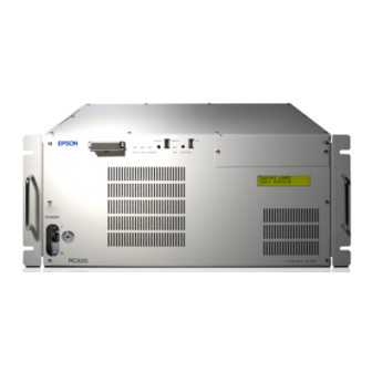
Setup & Operation 2. Part Names and Functions Part Names and Functions 2.1 Part Names Front RC620 (3) (4) (12) (10) (11) (13) (14)-2 (14)-1 (15) RC620-UL (Side and Back are the same as RC620.) (3) (4) (12) (13) (14)-2 (14)-1 (15) RC620 Rev.8... - Page 31 Setup & Operation 2. Part Names and Functions Side (16) (17) Back (18) (20) (23) (19) (24) (21) (22) (26) (27) (25) (28) (29) (34) (30) (31) (32) (33) RC620 Rev.8...
-
Page 32: Functions
Setup & Operation 2. Part Names and Functions 2.2 Functions (1) TP port Connects Teach Pendant TP1 (Option). For details, refer to Setup & Operation 7. TP Port. NOTE - When connecting the Teach Pendant (option) to the TP port, make sure the connector is right side up. - Page 33 Setup & Operation 2. Part Names and Functions (11) Lockout key for POWER switch Lock the POWER switch in Off status. You need this method in the maintenance or repair of the robot system and make sure the power is locked in Off status and other operators cannot operate.
- Page 34 Setup & Operation 2. Part Names and Functions (23) R-I/O connector This connector is for the input signals used for the real time I/O function. (24) EMERGENCY connector This connector is for input/output from/to Emergency Stop and Safety Door switches. For details, refer to the Setup &...
-
Page 35: Led And Lcd
: The 1 line lights up and the 2 line is turned off for approx. 10 seconds. Then for few seconds, it displays as below: EPSON Robot Controller After Controller Startup : LED (TEACH, AUTO, PROGRAM) turns ON according to the current operation mode (TEACH, Auto, Program). - Page 36 Setup & Operation 2. Part Names and Functions When several Controller statuses occurred at one time, the status indicated earlier on the following table is displayed. For an example, when both “Error” and “Teach” occurred at one time, “Error” is displayed. Controller status Display of LCD Execute Controller status...
- Page 37 Refer to Maintenance 4. Backup and Restore. Recovery Mode 9998 AC power supply drop is detected and software shut down. AC Power Off Software shut down is specified from the EPSON RC+ 6.0 9997 (software) or the SPEL program. Controller shutdown *1 When the Initialize Error occurs, reboot the Controller.
-
Page 38: Safety Features
Setup & Operation 2. Part Names and Functions 2.4 Safety Features The robot control system supports safety features described below. However, the user is recommended to strictly follow the proper usage of the robot system by thoroughly reading the attached manuals before using the system. Failure to read and understand the proper usage of the safety functions is highly dangerous. - Page 39 Setup & Operation 2. Part Names and Functions Motor Speed Error Detection The dynamic brake circuit is activated when the system detects that the motor is running at incorrect speed. Positioning Overflow –Servo Error- Detection The dynamic brake circuit is activated when the system detects that the difference between the Manipulator’s actual position and commanded position exceeds the margin of error allowed.
-
Page 40: Installation
Manual installer *2 1 CD *1 Required to connect IDE device. Be careful not to lose. *2 Attached when the manual(s) in the EPSON RC+ 6.0 installer DVD is revised. 3.2 Environmental Requirements ■ The Manipulator and the Controller must be used within the environmental conditions described in their manuals. -
Page 41: Installation
Setup & Operation 3. Installation If the Controller must be used in an environment that does not fulfill the conditions mentioned above, take adequate countermeasures. For example, the Controller may be enclosed in a cabinet with adequate ventilation and cooling. - Install indoors only. -
Page 42: Power Supply
Setup & Operation 3. Installation 3.3 Power Supply 3.3.1 Specifications Ensure that the available power meets following specifications. Item Specification Voltage AC 200 V to AC 240 V Phase Single phase Frequency 50/60 Hz Momentary Power 10 msec. Or less Interrupt Power Consumption Max. -
Page 43: Ac Power Cable
Setup & Operation 3. Installation 3.3.2 AC Power Cable ■ Make sure that cable manufacturing and connection are done by a qualified personal. When proceeding, be sure to connect the earth wire of the AC power cable colored green/yellow on the Controller to the earth terminal of the factory power supply. The equipment must be grounded properly at all times to avoid the risk of electric shock. -
Page 44: Typical Cable Connection
Setup & Operation 3. Installation 3.4.1 Typical Cable Connection Disconnectable connector Cable attached at delivery Cable prepared by users (1)AC Power Cable AC200V-240V (2) M/C Power Cable Manipulator (3) M/C Signal Cable (2) M/C Power Cable (3) M/C Signal Cable Additional axis (4) EMERGENCY Cable Emergency Stop... -
Page 45: Connecting Manipulator To Controller
Setup & Operation 3. Installation (5) I/O cable This connector is used for external input/output devices. For details, refer to the Setup & Operation 9. I/O Connector. (6) LAN (EtherNet) cable Connect the EtherNet device. For details, refer to the Setup & Operation 6. LAN (Ethernet Communication) Port. (7) PS/2 cable Dual-head cable for the connection of keyboard and mouse. -
Page 46: Noise Countermeasures
Setup & Operation 3. Installation 3.5 Noise Countermeasures To minimize electrical noise conditions, the following items must be observed in the system’s cable wiring: To minimize electrical noise condition, be sure of followings for wiring. - The earth wire of the power supply should be grounded. (Ground resistance: 100 Ω or less) It is important to ground the frame of Controller not only for prevention from electric shock, but also for reducing the influence of electric noise around the Controller. -
Page 47: Operation Mode (Teach/Auto)
Setup & Operation 4. Operation Mode (TEACH/AUTO) Operation Mode (TEACH/AUTO) 4.1 Overview The Robot system has two operation modes TEACH mode and AUTO mode. TEACH mode Controller Program mode AUTO mode Auto mode TEACH mode This mode enables point data teaching and checking close to the Robot using the Teach Pendant. -
Page 48: Program Mode (Auto)
Procedures for switching to the Program mode are the followings. Set the start mode of the EPSON RC+ 6.0 to “Program” and start up the Controller. 4.3.2 Setup from EPSON RC+ 6.0 Switch the start mode to Program mode from the EPSON RC+ 6.0. -
Page 49: Auto Mode (Auto)
Auto mode (AUTO) is for automatic operation of the Robot system. Procedures for switching to the Auto mode (AUTO) are the followings. A : Set the start mode of the EPSON RC+ 6.0 to “Auto” and start the Controller. B : Set the Controller to the Independent mode. - Page 50 Setup & Operation 4. Operation Mode (TEACH/AUTO) Set the Controller to Independent mode. (1) Select EPSON RC+ 6.0 menu | Setup | System Configuration to display the [System Configuration] dialog. (2) Select SPEL Controller Board | Preference. (3) Check [Independent Mode] check box.
-
Page 51: Setup From Control Device
Setup & Operation 4. Operation Mode (TEACH/AUTO) 4.4.3 Setup from Control Device Set the control device from EPSON RC+ 6.0. (1) Select EPSON RC+ 6.0 menu | Setup | System Configuration to display the [System Configuration] dialog. (1) Select SPEL Controller Board | Configuration. -
Page 52: Memory Port
5.1 What is Controller Status Storage Function? This function saves various kinds of Controller data with one push to the USB memory. Data saved in USB memory is loaded to EPSON RC+ 6.0 to get the status of the Controller and the program simply and accurately. -
Page 53: Adoptable Usb Memory
Setup & Operation 5. Memory Port 5.2.2 Adoptable USB Memory Use USB memory that meets the following conditions. - USB2.0, USB1.1 supported - Without security function USB memory with password input function cannot be used. - No installation of a driver or software is necessary for Windows. - Without encryption protection or security software. -
Page 54: Controller Status Storage With Teach Pendant (Option)
(4) Press thekey to save the status. 5.3.3 Load Data with EPSON RC+ 6.0 The following shows the procedure to read the data stored in the USB memory by EPSON RC+ 6.0 and display the Controller status. (1) Insert the USB memory into the PC with EPSON RC+ 6.0. -
Page 55: Transfer With E-Mail
(3) Send all the folders by e-mail. - Delete files that do not relate to the project before transfer. NOTE - This function is used to send the data to the system director and EPSON from the end users for problem analysis. RC620 Rev.8... -
Page 56: Details Of Data
VXDWORK.bin All files related to Project When [Include project files when status project except exported] check box is checked in EPSON ProjectName.obj RC+ 6.0 menu | Setup | System Configuration | Controller | Preference, the project file is stored. Includes program files. -
Page 57: Lan (Ethernet Communication) Port
RC+ 6.0 Online Help or User’s Guide 12. TCP/IP Communications. - Refer to EPSON RC+6.0 option Vision Guide 6.0 manual for other details of connection of the Controller and the Smart Camera. - This port is not used for EtherNet/IP. Use the port for fieldbusI/O board. For other... -
Page 58: Ip Address
6.3.1 LAN-1 port Change the IP address of LAN-1 port. (1) Select the EPSON RC+ 6.0 menu | Setup | Controller to display the [Setup Controller] dialog. (2) Enter the proper IP address and subnet mask and click thebutton. - Page 59 Setup & Operation 6. LAN (Ethernet Communication) Port 6.3.2 LAN-2 port The IP address of LAN-2 port can be changed in the normal steps of Windows. RC620 Rev.8...
-
Page 60: Tp Port
Setup & Operation 7. TP Port TP Port The TP port connects the Teach Pendant to the Controller. For the details, refer to Setup & Operation 13. Option: Teach Pendant. Example When nothing is connected to the TP port, Emergency Stop status occurs in the Controller. When the Teach Pendant is not connected, connect the TP/OP bypass plug. -
Page 61: Emergency
Setup & Operation 8. EMERGENCY EMERGENCY The details of safety requirements for this section are described in the Users Guide 2. NOTE Safety. Please refer to them to keep the robot system safe. Connect a safeguard switch or Emergency Stop switch to the Controller EMERGENCY connector for safety. -
Page 62: Safety Door Switch And Latch Release Switch
Setup & Operation 8. EMERGENCY 8.1 Safety Door Switch and Latch Release Switch The EMERGENCY connector has input terminals for the Safety Door switch and the Emergency Stop switch. Be sure to use these input terminals to keep the system safe. Connector Standard D-sub 25 male pin... -
Page 63: Latch Release Switch
Setup & Operation 8. EMERGENCY 8.1.2 Latch Release Switch The controller software latches these conditions: - The safety door is open. - The operation mode is set to “TEACH”. The EMERGENCY connector has an input terminal for a latch release switch that cancels the latched conditions. -
Page 64: Emergency Stop Switch Connection
Setup & Operation 8. EMERGENCY 8.2 Emergency Stop Switch Connection 8.2.1 Emergency Stop Switch If it is desired to add an external Emergency Stop switch(es) in addition to the Emergency Stop on the Teach Pendant and Operator Panel, be sure to connect such Emergency Stop switch(es) to the Emergency Stop input terminal on the EMERGENCY connector. -
Page 65: Pin Assignments
Setup & Operation 8. EMERGENCY 8.3 Pin Assignments The EMERGENCY connector pin assignments are as follows: Pin No. Signal Function Pin No. Signal Function ESW11 Emergency Stop switch contact (1) ESW21 Emergency Stop switch contact (2) ESW12 Emergency Stop switch contact (1) ESW22 Emergency Stop switch contact (2) ESTOP1+ Emergency Stop circuit 1 (+) -
Page 66: Circuit Diagrams
Setup & Operation 8. EMERGENCY 8.4 Circuit Diagrams 8.4.1 Example 1: External emergency stop switch typical application External Emergency Controller Stop switches +24V Emergency Stop switch of an Operation Unit (TP) Main Circuit Control + − Motor Driver AC Input Emergency Stop detection External... -
Page 67: External Safety Relay Typical Application
Setup & Operation 8. EMERGENCY 8.4.2 Example 2: External safety relay typical application Controller External +24V Fuse +24V Emergency Stop switch of an Operation Unit (TP) External +24V External +24V External safety relay Main Circuit (The above diagram Control is simplified for representation.) * For the protection of the emergency stop circuit,... -
Page 68: I/O Connector
Setup & Operation 9. I/O Connector 9. I/O Connector The I/O connector is for connecting your input/output equipment to the system. Pins Bit number Input 0 to 23 Control Unit Output 0 to 15 Input 32 to 55 Drive Unit 1 Output 32 to 47 Input... - Page 69 Setup & Operation 9. I/O Connector Typical Input Circuit Application 1 I/O-1 GND +DC 1 Input No.0 to 7 common 2 Input No.0 3 Input No.1 (Same) 4 Input No.2 (Same) 5 Input No.3 (Same) 6 Input No.4 (Same) 7 Input No.5 (Same) 8 Input No.6 (Same)
-
Page 70: Output Circuit
Setup & Operation 9. I/O Connector 9.2 Output Circuit : +12 V to 24 V ±10% Rated Output Voltage Maximum Output Current : TYP 100 mA/1 output Output Driver : PhotoMOS Relay On-State Resistance (average) : 23.5 Ω or less Two types of wiring are available for use with the nonpolar photoMOS relay in the output circuit. - Page 71 Setup & Operation 9. I/O Connector Typical Output Circuit Application 1 I/O-1 10 Output No.0 Load 11 Output No.1 (Same) 12 Output No.2 (Same) 13 Output No.3 (Same) 14 Output No.4 (Same) 15 Output No.5 (Same) 27 Output No.6 (Same) 28 Output No.7 17 Output No.0 to 7 common (GND) (Same)
-
Page 72: Pin Assignment
Setup & Operation 9. I/O Connector 9.3 Pin Assignments Signal Name Signal Name Signal Name Input common No. 0 to 7 Input common No. 8 to 15 Input common No. 16 to 23 Input No. 0 Input No. 8 Input No. 16 Input No. -
Page 73: I/O Remote Settings
10. I/O Remote Settings This section describes the functions of input and output signals. For details, refer to the EPSON RC+ Users Guide 10. Remote Control. The remote functions may be assigned to your standard I/O board(s), expansion I/O board(s), or fieldbus I/O board(s) to enhance robot system control - either from an operational unit of your choice or a sequencer. -
Page 74: R-I/O Connector
If you use this function with Vision, you can create an application of parts pickup, alignment, and assembly by robots without stopping. For details, refer to EPSON RC+6.0 Users Guide - Real time I/O. In the case of 6-axis robot, this function can not be used. -
Page 75: Pin Assignment
Setup & Operation 11. R-I/O Connector Typical Input Circuit Application 2 R-I/O GND +24V INPUT No.24-1 INPUT No.24-2 INPUT No.25-1 INPUT No.25-2 11.2 Pin Assignments Signal Name INPUT No24-1 INPUT No24-2 INPUT No25-1 INPUT No25-2 5 to 15* * For the pins 5 to 15, do not connect anything. Connector Standard D-sub 50 male pin... -
Page 76: Option Units
Max. 3 PCI boards can be installed to the PCI slots. As the option board, the following 2 types are provided. - Frame grabber board (Refer to the EPSON RC+ 6.0 Option Vision Guide 6.0 manual.) - Fieldbus I/O master board (Refer to the RC620 Option Fieldbus I/O manual.) -
Page 77: Expansion I/O Board
Setup & Operation 12. Option Slots 12.2 Expansion I/O Board 12.2.1 About Expansion I/O Board Each additional expansion I/O board provides 32 inputs and 32 outputs. CN1: 16 inputs / 16 outputs CN2: 16 inputs / 16 outputs The number of I/Os that can be expanded is maximum 4 boards and 128 inputs and outputs. -
Page 78: Confirmation With Epson Rc+6.0
I/O board. Therefore, no software configuration is needed. Correct identification can be confirmed from EPSON RC+ 6.0. (1) Select the EPSON RC+ 6.0 menu-[Setup]-[System Configuration] to display the [System Configuration] dialog. (2) Select the [Inputs / Outputs]. - Page 79 Setup & Operation 12. Option Slots Protected Expansion I/O Board Typical Input Circuit Application 1 Expansion I/O board-1 GND +DC 1 Input No.64 to 71 common 2 Input No.64 3 Input No.65 (Same) 4 Input No.66 (Same) 5 Input No.67 (Same) 6 Input No.68 (Same)
-
Page 80: Output Circuit
Setup & Operation 12. Option Slots 12.2.5 Output Circuit : +12 V to 24 V ±10% Rated Output Voltage Maximum Output Current : TYP 100 mA/1 output Output Driver : PhotoMOS Relay On-State Resistance (average) : 23.5 Ω or less Two types of wiring are available for use with the nonpolar photoMOS relay in the output circuit. - Page 81 Setup & Operation 12. Option Slots Protected Expansion I/O Board Typical Output Circuit Application 2 Expansion I/O-1 10 Output No.64 Load 11 Output No.65 (Same) 12 Output No.66 (Same) 13 Output No.67 (Same) 14 Output No.68 (Same) 15 Output No.69 (Same) 27 Output No.70 (Same)
-
Page 82: Pin Assignments
Setup & Operation 12. Option Slots 12.2.6 Pin Assignments Pin Assignment table of the 1 Expansion I/O board. Connector 1 Pin Assignments Signal Name Signal Name Signal Name 18 Input common No.72 to 79 Input common No.64 to 71 19 Input No.72 Input No.64 Input No.65 20 Input No.73... -
Page 83: Fieldbus I/O Board
Setup & Operation 12. Option Slots Connector 2 Pin Assignments Signal Name Signal Name Signal Name Input common No.80 to 87 18 Input common No.88 to 95 Input No.80 19 Input No.88 Input No.81 20 Input No.89 21 Input No.90 Input No.82 Input No.83 22 Input No.91... -
Page 84: Rs-232C Board
Setup & Operation 12. Option Slots 12.4 RS-232C Board 12.4.1 About the RS-232C Board The RS-232C option accepts four ports expansion per board. A maximum of two boards, eight ports expansion is available for RS-232C board. Port numbers are assigned as follows. Port No. -
Page 85: Verify With Epson Rc+5.0 (Rs-232C)
When an RS-232C board is mounted in as option slot, the Controller software automatically identifies the RS-232C board. Therefore, no software configuration is needed. Correct identification can be confirmed from EPSON RC+ 6.0. (1) Select the EPSON RC+ 6.0 menu-[Setup]-[System Configuration] to display the [System Configuration] dialog. (2) Select the [RS-232C]. NOTE RC620 controller has one or two communication ports as standard. -
Page 86: Rs-232C Software Communication Setup (Rs-232C)
Parity Odd, even, NA Terminator CR, LF, CRLF Refer to EPSON RC+ 6.0 Online Help or 11. RS-232C Communications for RS-232C communication from the Robot application. 12.4.5 Communication Cable (RS-232C) Prepare a communication cable as described in this section. Connector... - Page 87 Manipulator makes an emergency stop. Normal Shutdown of Robot System Exit EPSON RC+ 6.0 and shut down Windows. After the Windows shutdown, make sure the LCD panel is turned OFF and then turn OFF the power switch of the Controller.
- Page 88 ■ When handling the UPS battery (nickel hydride battery), observe the following precautions for safe use. Be sure to use the battery supplied as the maintenance parts from EPSON. (Refer to Maintenance 9. Maintenance Parts List.) Do not allow the positive (+) and negative (-) electrodes to short circuit.
-
Page 89: Safety
Setup & Operation 14. Option : Teach Pendant TP1 14. Option : Teach pendant TP1 Here describes the functions and operating instructions of the Teach Pendant TP1 – Option for the Robot controller. 14.1 Function 14.1.1 Safety For details of Safety, refer to Safety Chapter in the User’s Guide. Please read and understand the chapter before using the robot system. - Page 90 Setup & Operation 14. Option : Teach Pendant TP1 Immediately press the EMERGENCY STOP switch whenever you suspect any danger. The Teach Pendant is equipped with an EMERGENCY STOP switch. Before operating the Teach Pendant, make sure that the EMERGENCY STOP switch on the Teach Pendant functions properly.
- Page 91 Setup & Operation 14. Option : Teach Pendant TP1 The Teach Pendant must be used within the environmental conditions described in this manual. This product has been designed and manufactured strictly for use in a normal indoor environment. Using this product in the environment that exceeds the conditions may not only shorten the life cycle of the product but also cause serious safety problems.
-
Page 92
Setup & Operation 14. Option : Teach Pendant TP1 E-STOP Lamp (4) Press the
key on the operation panel to reset the Emergency Stop. (5) Make sure that the E-STOP lamp on the operation panel is OFF. Key Mode Selector Key Switch The mode selector key switch is used to select TEACH or AUTO operation mode. -
Page 93: Specifications
Setup & Operation 14. Option : Teach Pendant TP1 14.1.2 Specifications Part Names and Functions Front view Back view (1) Mode Selector Key switch The mode selector key switch is used to change the operation mode between TEACH and AUTO. The mode can be fixed by pulling out the key. When the mode is switched while a program is executing, the program will be stopped. - Page 94 Setup & Operation 14. Option : Teach Pendant TP1 (6) Enable switch This is a three-position switch. Motion and I/O output commands are available while the switch is gripped when the Teach Pendant is operated in TEACH mode. The switch turns ON when it is at the midpoint, and it turns OFF when it is fully gripped or released.
-
Page 95: Installation
Setup & Operation 14. Option : Teach Pendant TP1 14.1.3 Installation Contents TP1 (with cables) : 1 unit Mode selector key : 2 units Environmental Conditions The Teach Pendant must be used in an environment that conforms to the following requirements to ensure safe and reliable operation. - Page 96 Setup & Operation 14. Option : Teach Pendant TP1 Connection This section indicates the connection of the Controller and the Teach Pendant. Be sure to connect the cables of Controller and Teach Pendant properly. Do not allow unnecessary strain on the cables. (Do not put heavy objects on the cables. Do not bend or pull the cables forcibly.) The unnecessary strain on the cables may result in damage to the cables, disconnection, and/or contact failure.
- Page 97 Setup & Operation 14. Option : Teach Pendant TP1 Connection to the Controller (1) Make sure that the Controller and the Robot is connected properly. (2) Connect the connector of the Teach Pendant cable to the TP port of Controller RC620. (3) Turn ON the controller RC620.
- Page 98 Setup & Operation 14. Option : Teach Pendant TP1 Wall Bracket (Option) Outer Dimension [Unit :mm] 201.4 56.2 Detail : J Detail : K Front View Hook A 39.6 Hook B Back View Side View RC620 Rev.8...
- Page 99 Setup & Operation 14. Option : Teach Pendant TP1 Mount and Use Mount the Teach Pendant with the wall bracket in the following procedures. (1) Secure the wall bracket to the wall with three screws (positions are indicated by dotted line in the Outer Dimension). (2) Hang the handle of the Teach Pendant to Hook A.
-
Page 100: Operation Mode(Teach/Auto
Setup & Operation 14. Option : Teach Pendant TP1 14.1.4 Operation Mode(TEACH/AUTO) A coordinate point including the arm pose is defined as “position (point),” and the data is NOTE called “point data.” Outline Robot system has two operation modes TEACH mode and AUTO mode. TEACH mode This mode enables point data teaching and check close from the Robot using the Teach Pendant. - Page 101 Setup & Operation 14. Option : Teach Pendant TP1 AUTO mode Print Window 13.4.1 Program Command Display I/O Monitor 13.4.2 I/O Monitor Memory I/O Monitor 13.4.3 Memory I/O Monitor Task Monitor 13.4.4 Task Monitor System History 13.4.5 System History Controller Statuses 13.4.6 Controller Statuses Preservation Preservation Date / Time...
-
Page 102: Operation Panel (Key Description)
Setup & Operation 14. Option : Teach Pendant TP1 14.1.5 Operation Panel (Key Description) Key Description E-STOP lamp Safety lamp Alphabet and Number Input keys Jog keys Reset key Arrow keys Motor key Home key Cancel key Teaching keys OK key Function keys Alphabet and Number Input Keys Input mode alphabet/number switches by turning ON/OFF the “Alph”... -
Page 103
Setup & Operation 14. Option : Teach Pendant TP1 Arrow Keys Mode switches by turning ON/OFF the “F5-8” lamp. Press the
key to turn ON/OFF the “F5-8” lamp. F5-8 Mode Function +1 the value ↑ Move the cursor up −1 the value ↓... - Page 104 Setup & Operation 14. Option : Teach Pendant TP1 Jog Keys Jog key is available only in TEACH mode. Function Moves the target joint (X to W, J1 to J6) to − direction − Moves the target joint (X to W, J1 to J6) to + direction Teaching Keys Teaching key is available only in TEACH mode.
-
Page 105: Enable Switch
Setup & Operation 14. Option : Teach Pendant TP1 14.1.6 Enable Switch In TEACH mode, several operations require use of the 3-position enable switch located on the left rear of the pendant. The enable switch can be operated either hand. When the enable switch is required to execute an operation, you must grip the switch to the center (enable) position. -
Page 106: Teaching Procedure
Setup & Operation 14. Option : Teach Pendant TP1 14.2 Teaching Procedure The basic jog operation and teaching procedure is indicated. Switch the mode selector switch to “Teach” to display the following screen. - A coordinate point including the arm pose is defined as “position (point),” and the data NOTE ... -
Page 107: Teaching
Setup & Operation 14. Option : Teach Pendant TP1 14.2.2 Teaching Apply the Robot position to the specified point number. (1) Specify the point number by changing the value in the [Point] using the <↑> and <↓> keys in the [Jog & Teach] screen. [Label] display changes by changing the point number. -
Page 108: Direct Teaching
Setup & Operation 14. Option : Teach Pendant TP1 14.2.3 Direct Teaching “Direct teach” is a way to teach the Robot directly by setting the teaching joint to servo-OFF. Apply the Robot position to the specified point number. NOTE The 6-axis robot cannot be moved by hand, execute the jog instead. -
Page 109
Setup & Operation 14. Option : Teach Pendant TP1 (6) Press the
key, the following screen appears. When the point number is already used, the following screen appears. (7) Press the key to assign the robot position. (8) Press the key to display the following screen. Press the ... -
Page 110: Teach Mode
Setup & Operation 14. Option : Teach Pendant TP1 14.3 TEACH Mode Switch the mode selector key switch to “Teach” to enter the TEACH mode. In this mode, jog, teaching, operation commands, I/O commands, and other operations and commands can be executed using the Teach Pendant. Note, however, that the program cluster cannot be executed. -
Page 111: Jog & Teach
Setup & Operation 14. Option : Teach Pendant TP1 14.3.1 Jog & Teach This section indicates settings in the [Jog & Teach] screen. (1) Switch the mode selector key switch to “Teach” to display the following screen. (2) Set the data items currently displayed in the [Jog & Teach] screen. See (described hereinafter) : Specifying Point Number Specifying Jog Mode Specifying Jog Speed Jog key... -
Page 112
Setup & Operation 14. Option : Teach Pendant TP1 Specifying Jog Speed Press the
key and select the speed at [Speed]. (Low, High) Low : Low jog speed High : High jog speed Jog key The moving direction or joint is displayed in the left side of the Jog key. If the robot has 6 or more axes, the three keys shown below are switched when pressing NOTE ... -
Page 113
Setup & Operation 14. Option : Teach Pendant TP1 Executing Step Jog By step jog operation, the robot moves when the Jog key is pressed. Set the distance that the robot moves beforehand. (1) Press the
key and select the distance at [Jog Dist]. Long : Long jog distance Medium : Medium jog distance... -
Page 114
Setup & Operation 14. Option : Teach Pendant TP1 When the point number is already used, the following screen appears. (2) Press the
key to assign the point data. (3) Press the key. This can also be executed in the [Point Editor] screen. Saving Point File (1) Press the ... -
Page 115: Point Editor
Setup & Operation 14. Option : Teach Pendant TP1 (2) Press thekey to load the point data in the file memory. NOTE This can also be executed in the [Point Editor] screen. Select whether if you want to save the point file. : Save the new settings and load the point file. -
Page 116
Setup & Operation 14. Option : Teach Pendant TP1 Specifying Point Number There are two ways to specify the point number. (1) Specify the point number by changing the value in the [Point] using the <↑> and <↓> keys. Chang the point number to change the indication at [Label]. (2) Change the [Point] values directly and press the
... -
Page 117: Robot
Setup & Operation 14. Option : Teach Pendant TP1 14.3.3 Robot This section indicates settings in the [Robot] screen. Press thekey in the [Jog & Teach] screen. The following screen appears. When a value has been changed, press the key to apply the value, and be sure to press the ... -
Page 118: Motion Command
Setup & Operation 14. Option : Teach Pendant TP1 14.3.4 Motion Command 6-Axis robots This item indicates the procedure for executing motion commands when using 6-Axis robots (1) Press thekey in the [Jog & Teach] screen. The following screen appears. Move the cursor to the desired motion command, and press the ... -
Page 119: I/O Command
Setup & Operation 14. Option : Teach Pendant TP1 14.3.5 I/O Command This section indicates settings in the [I/O Command] screen. Press thekey in the [Jog & Teach] screen. The following screen appears. Switching Input/Output Status Display Press the key to switch between the “Inputs” status and the “Outputs” status display. Output Bit ON/OFF (1) Press the ... -
Page 120: Jog Distance
Setup & Operation 14. Option : Teach Pendant TP1 14.3.6 Jog Distance This section indicates settings in the [Jog Distance] screen. Press thekey in the [Jog & Teach] screen. The following screen appears. When a value has been changed, press the key to apply the value, and be sure to press the ... -
Page 121: Free Joints
Setup & Operation 14. Option : Teach Pendant TP1 14.3.7 Free Joints This section indicates settings in the [Free Joints] screen. Press thekey in the [Jog & Teach] screen. The following screen appears. Specify On/Off for each joint. When performing direct teaching (manually moving the robot by hand to perform teaching), set the joint to Off. -
Page 122: Brake (For 6-Axis Robots)
Setup & Operation 14. Option : Teach Pendant TP1 14.3.8 Brake (6-Axis robots only) This section indicates the brake ON / OFF switching for each joint. NOTE When you use the 6-axis robot, thekey is displayed. (1) Press the key in the [Jog & Teach] screen. The following screen appears. The following screen appears when the password is set up. -
Page 123
Setup & Operation 14. Option : Teach Pendant TP1 To turn the brake ON (2) Press the
key. The brake is locked. To turn the brake OFF (2) Press the ... -
Page 124: Auto Mode
Setup & Operation 14. Option : Teach Pendant TP1 14.4 AUTO Mode Switch the mode selector key switch to “Auto” to enter the AUTO mode. AUTO mode is used for the automatic operation (executing programs) in the field running and state reference of the robot system. Note, however, that the program cluster cannot be executed. -
Page 125: Program Command Display
Setup & Operation 14. Option : Teach Pendant TP1 14.4.1 Program Command Display The [Print] screen appears when the mode selector key switch is switched to “Auto”. To display the [Print] screen from the [Main Menu] screen, move the cursor to [0 Print Panel], and press the... -
Page 126: I/O Monitor
Setup & Operation 14. Option : Teach Pendant TP1 14.4.2 I/O Monitor This screen displays the bit status of I/O. In the [Main Menu] screen, move the cursor to [1 I/O Monitor], and press thekey. Displays the item Bit #, Status # and label in this order from the left. I/O status (Inputs, bit units) “*”... -
Page 127: Task Monitor
Setup & Operation 14. Option : Teach Pendant TP1 14.4.4 Task Monitor This screen displays the status of tasks. In the [Main Menu] screen, move the cursor to [3 Task Monitor], and press thekey. Displays the item Number, Status, Type, and Name in this order from the left. When the task name is too long to display the whole name, a tilde is attached at the end of the task name as “LongTaskName_1234567890~”. -
Page 128: System History
Setup & Operation 14. Option : Teach Pendant TP1Switches the task status display (Trap task or Back ground task). The [Main Menu] screen appears. 14.4.5 System History This screen displays a history of errors, operations and warnings that occurred in the past. In the [Main Menu] screen, move the cursor to [4 System History], and press the ... -
Page 129: Controller Statuses Preservation
Setup & Operation 14. Option : Teach Pendant TP1 14.4.6 Controller Statuses Preservation Indicate the procedure to save the status of the Controller to the USB memory. (1) Insert the USB memory into the Controller. (2) In the [Main Menu] screen, move the cursor to [5 Controller States...], and press the... -
Page 130: Brightness / Contrast
Setup & Operation 14. Option : Teach Pendant TP1 14.4.8 Brightness / Contrast (1) In the [Main Menu] screen, move the cursor to [7 Brightness / Contrast], and press thekey. (2) Adjust the brightness and contrast. Press the key to save the status. <↓><↑>... -
Page 131: Error
Setup a password to limit operators for the brake equipment (6-axis robot only). TEACH mode ..[Jog&Teach]-[Brake] 6-Axis robot only Follow the procedure below to set the password. (1) Select EPSON RC+6.0 menu-[Setup]-[System Configuration]-[SPEL Controller Board]-[Configuration] to display the following screen. (2) Click thebutton at “TP Password.”... -
Page 132: Troubleshooting
An Error code appears and the Robot does not operate normally - Please refer to the error code indicated in the following manual. EPSON RC+6.0 SPEL+ Language reference Robot does not move by pressing the Jog key - Execute the Motor On command to energize the Robot motor. -
Page 133: Option: Raid
Setup & Operation 15. RAID 15. Option: RAID Here describes the functions and operating instructions of the RAID – Option for the Robot controller. 15.1 Overview RAID option provides the function of RAID1 (mirroring). Do not remove the HDD with RAID system because it may break the RAID system. Do not remove the HDD except when it has a failure. -
Page 134: Status For Restore
Setup & Operation 15. RAID 15.2.2 Status for Restore When the mirroring brakes and requires the restoration, it displays “A hard drive is missing, the system is functioning normally. However, data protection is no longer available.” on the Intel Matrix Storage Console. Check the port number that running normally, and restore the data protection status. -
Page 135: Restoring The Data Protection Status
Setup & Operation 15. RAID 15.3 Restoring the Data Protection Status Follow the instruction below and restore the data protection status. 15.4.1 Shutdown the system 15.4.2 Replace the HDD 15.4.3 Restore the data protection status 15.3.1 Shutdown the system (1) Check the port which is normally running. To check the port which is normally running, execute the Intel Matrix Storage Console NOTE ... -
Page 136
Setup & Operation 15. RAID (4) Click the
. (5) Click the button. The restoration (rebuild of the volume) starts. This process requires approx. 40 minutes. (6) When the restoration is completed, it displays as below. (7) Exit the Intel Matrix Storage Console. -
Page 137: Maintenance
Maintenance This section contains maintenance procedures for the Robot Controller. -
Page 139: Safety Precautions On Maintenance
Maintenance 1. Safety Precautions on Maintenance Safety Precautions on Maintenance 1.1 Safety Precautions ■ Only authorized personnel who have taken the safety training should be allowed to execute teaching or calibration of the robot system. The safety training is the program for industrial robot operator that follows the laws and regulations of each nation. -
Page 140: Lockout / Tagout
Maintenance 1. Safety Precautions on Maintenance ■ Do not lose the screws removed at maintenance. When the screw is dropped into the Controller, be sure to take it out. Leaving the screw in the Controller may cause short circuit and may result in equipment damage to the parts and/or robot system. -
Page 141: Regular Maintenance Inspection
Maintenance 2. Regular Maintenance Inspection Regular Maintenance Inspection Performing regular maintenance inspection properly is essential for preventing trouble and maintaining safety. This chapter describes the schedules for maintenance inspection and procedures. Be sure to perform the maintenance inspections in accordance with the schedules. 2.1 Schedule for Maintenance Inspection Inspection points are divided into five stages: daily, monthly, quarterly, biannual, and annual. -
Page 142: Inspection Point
Maintenance 2. Regular Maintenance Inspection 2.2 Inspection Point 2.2.1 Inspection While the Controller is Turned OFF Inspection Point Inspection Location Daily Monthly Quarterly Biannual Annual Visually check for External appearance external defects. of Controller Clean up if necessary. ... -
Page 143: Controller Structure
Maintenance 3. Controller Structure Controller Structure 3.1 Location of Parts Top panel Front Right side panel Left side panel Front panel Bottom panel Back Back panel 3.2 Diagram of Cable Connections For the connections of controller inner cables, refer to the following diagram. The diagram is a simplified development view inside the Controller. - Page 144 Maintenance 3. Controller Structure When connecting 2 units of the 4-axis manipulator RC620 Rev.8...
- Page 145 Maintenance 3. Controller Structure When connecting one 6-axis manipulator and one X5 series RC620 Rev.8...
- Page 146 Maintenance 3. Controller Structure Cable List Connector pin Wire Connector pin Connection Connection Note Quantity Quantity Quantity Circuit protector, − AC Input Connector − − Circuit protector Noise filter − Noise filter Switching Power Supply (15V) Switching Power Supply (24V) PC Power Supply Regenerative Control Board...
-
Page 147
Maintenance 3. Controller Structure Connector pin Wire Connector pin Connection Connection Note Quantity Quantity Quantity 4,10 DMB, FPB (High speed) 6,16,4 PCI-BPB (High speed) 7
HDD1 7 HDD2 26 DVD drive 4,4,4,4,2,2 M/C power connector FAN1 LCD module 36,4 Battery 34 ... -
Page 148: Connector Pin Assignment
Maintenance 3. Controller Structure 3.3 Connector Pin Assignment Pin assignments differ depending on the manipulator type. The following tables show the pin assignments for the M/C power connector and M/C signal connectors. For EMERGENCY and TP connectors, refer to Setup & Operation. 3.3.1 M/C Power Connector G / RS / X5 series C3 series... -
Page 149: M/C Signal Connector
Maintenance 3. Controller Structure 3.3.2 M/C Signal Connector G / RS G / RS ENC_GND 26 ENC_GND ENC_GND ENC_GND ENC_5V ENC_5V ENC_5V EMC_5V ENC_5V 6 ENC_GND ENC_GND ENC_GND 31 ENC_GND ENC_GND ENC_5V ENC_5V ENC_5V ENC_5V ENC_5V 11 ENC_GND ENC_GND ENC_GND 36 ENC_GND ENC_GND ENC_5V ENC_5V... -
Page 150: Backup And Restore
Maintenance 4. Backup and Restore Backup and Restore 4.1 What is the Backup Controller Function? The controller configuration set by EPSON RC+ 6.0 can be stored with the “Backup Controller” function. The Controller settings can be restored easily using the data previously stored with “Backup Controller”... -
Page 151: Backup Data Types
Prg file is not included. All the files related Project related All the project files transferred to the to Project Controller. Includes program files when EPSON RC+ 6.0 is configured to transfer source code to the Controller. GlobalPreserves.dat Global Preserve Stores values... -
Page 152: Backup
4.3 Backup Backup the Controller status from the Teach Pendant (Option) or EPSON RC+ 6.0. (1) Select EPSON RC+ 6.0 menu | Tools | Controller to display the [Controller Tools] dialog. (2) Click thebutton to display the [Browse For Folder] dialog. -
Page 153: Restore
■ Do not edit the backup files. Otherwise, operation of the robot system after data CAUTION restoration to the Controller is not assured. (1) Select the EPSON RC+ 6.0 menu-[Tools]-[Controller] to display the [Controller Tools] dialog. (2) Click thebutton to display the [Browse For Folder] dialog. - Page 154 The default is unchecked. When a project is restored, the values of Global Preserve variables are loaded. For details about Global Preserve variable backup, refer to EPSON RC+ 6.0 User’s Guide 5.10.10 Display Variables Command (Run Menu). Vision hardware configuration checkbox This checkbox allows you to restore the vision hardware configuration.
-
Page 155: Firmware Update
Firmware (software stored in non-volatile memory) and data files necessary to control the Controller and the Robot are preinstalled in the Controller. Controller configuration set from EPSON RC+ is always saved in the Controller. Controller firmware is supplied by CD-ROM as needed. -
Page 156
Maintenance 5. Firmware Update (7) Check the current firmware version and the new firmware version and click the
button. (8) The firmware registration starts. It takes several minutes to complete. Do not power off the Controller during registration process. NOTE ... -
Page 157
Maintenance 5. Firmware Update (11) The following dialog appears after the Controller reboot. Click the
button. The firmware upgrade is complete. RC620 Rev.8... -
Page 158: Controller Recovery
Maintenance 5. Firmware Update 5.3 Controller Recovery If the Controller becomes inoperable, use the procedures described in this section to recover. Controller Backup is recommended for easy recovery of the Controller operation. For NOTE details of Controller Backup, refer to Maintenance 4. Backup and Restore. The following two conditions describe the Controller error status after turning on the Controller. -
Page 159: Firmware Initialization Procedure
The firmware initialization procedure described in this section. (1) Turn ON the Controller. (2) Shutdown the development software EPSON RC+ 6.0. (3) Copy the content of “firmware CD-ROM” to the USB memory and insert the USB memory to the controller USB port. -
Page 160
(10) The following dialog appears after the Controller reboot. Click the
button. The firmware upgrade is completed. Start EPSON RC+ 6.0 and restore the Controller settings. For details of restoring the operating system, refer to Maintenance 4. Backup and Restore. -
Page 161: Maintenance Parts Replacement Procedures
Maintenance 6. Maintenance Parts Replacement Procedures 6. Maintenance Parts Replacement Procedures Before performing any maintenance procedure, always make sure that the main power of the Controller is turned OFF and that the high voltage charged area is completely discharged. Performing any maintenance procedure while the main power is ON or the high voltage charged area is not WARNING... -
Page 162: Fan / Fan Filter
Maintenance 6. Maintenance Parts Replacement Procedures Fan Filters (1) Mount the fan filters (large one and small one) to the front panel. Installation (2) Secure the front panel using 6 screws to the Controller. (3) If you removed cables from TP port and USB port, connect them again. (4) Plug in the power connector. -
Page 163: Replacing The Large Fan
Maintenance 6. Maintenance Parts Replacement Procedures 6.1.2 Replacing the Large Fan Large Fan (1) Turn OFF the Controller. Removal (2) Remove cables from TP port and USB port on the front panel if they are connected. (3) Remove 6 screws and the front panel. (4) Remove 2 screws securing the Large Fan and the fan cover. - Page 164 Maintenance 6. Maintenance Parts Replacement Procedures Large Fan (1) Connect the cable connector of Large Fan to the DMB board. Installation Refer to Maintenance: 3.2 Diagram of Cable Connections. (2) Insert the Large Fan into the chassis. Pass the cable connector of Large Fan and Small Fan through the path shown in the photo.
-
Page 165: Replacing The Small Fan
Maintenance 6. Maintenance Parts Replacement Procedures 6.1.3 Replacing the Small Fan Small Fan (1) Turn OFF the Controller. Removal (2) Remove the Large Fan. Refer to Maintenance: 6.1.2 Replacing the Large Fan. (3) Remove the UPS Battery. Refer to Maintenance: 6.2.2 Replacing the UPS Battery. (4) Remove 2 screws securing the Small Fan and fan cover (Small). - Page 166 Maintenance 6. Maintenance Parts Replacement Procedures Small Fan (1) Pass the cable of Small Fan through the Installation way shown in the photo. Avoid the peripheral cables because the NOTE fan connector can be caught in the cables. Path of Small Fan cable (2) Connect the connector of Small Fan to the DMB.
-
Page 167: Battery
Observe the following precautions for safe use of lithium batteries. - Be sure to use the battery supplied as the maintenance parts from EPSON. (Refer to Maintenance 9. Maintenance Parts List.) - Do not allow the positive (+) and negative (-) electrodes to short circuit. - Page 168 Maintenance 6. Maintenance Parts Replacement Procedures (5) Remove a screw of the battery fittings located below the Large Fan. (6) Pull out the battery fittings and disconnect the relay connector. The lithium battery cable is connected NOTE to the main chassis. Be sure to pull it out slowly.
- Page 169 Maintenance 6. Maintenance Parts Replacement Procedures Battery (1) Put a new lithium battery in position and Installation secure it with a new wire tie. Bind the lithium battery below the battery NOTE level as shown in the photo. Cut off the redundant part of tie by nippers.
-
Page 170: Replacing The Ups Battery
Dispose of the used battery appropriately in accordance with the laws and acts of your national or local government. If you cannot dispose of a used battery properly, please inquire of your EPSON robot supplier how to dispose of it. UPS Battery (1) Turn OFF the Controller. - Page 171 Maintenance 6. Maintenance Parts Replacement Procedures (6) Push the relay connector latch and disconnect the connector. (7) Pull out the UPS battery and cut off the wire tie binding the UPS battery fuse. RC620 Rev.8...
- Page 172 Maintenance 6. Maintenance Parts Replacement Procedures UPS Battery (1) Put a new UPS battery fuse on the Installation UPS battery fixing plate and secure it with an attached wire tie. Position the cable tie as show in the NOTE photo.
-
Page 173: Motor Driver
Maintenance 6. Maintenance Parts Replacement Procedures 6.3 Motor Driver 6.3.1 Part Name Main circuit connector Heatsink Input/Output signal connector Face plate 750W (with Dynamic brake resistor cable) 50 W, 100 W, 200 W, 400 W For the wattage of the motor driver, see the model type described on the face plate. Also, the wattage of the installed motor driver corresponds with the wattage of the driving motor. -
Page 174: Replacing The Motor Driver (Dmb Side)
Maintenance 6. Maintenance Parts Replacement Procedures 6.3.2 Replacing the Motor Driver (DMB side) Record the relation of the model type and wattage when removing the motor driver to install a new motor driver of correct wattage. If you install a motor driver of CAUTION wrong wattage, the robot system cannot operate properly. - Page 175 Maintenance 6. Maintenance Parts Replacement Procedures (5) Remove 2 finger screws and the plate on which the switching power supply is mounted. Use these finger screws to pull out the NOTE motor driver. (6) Remove 5 finger screws and motor driver mounting bracket.
- Page 176 Maintenance 6. Maintenance Parts Replacement Procedures When G1 / G3 / G6 / C3 / RS manipulator is connected, start with the installation step Motor Driver (3). (DMB side) When G10 / G20 manipulator is connected, start with the installation step (1). Installation (1) When connecting the motor driver (750 W), insert it slowly along the guide rail,...
-
Page 177: Replacing The Motor Driver (Admb Side)
Maintenance 6. Maintenance Parts Replacement Procedures 6.3.3 Replacing the Motor Driver (ADMB side) Motor Driver (1) Turn OFF the Controller power and disconnect the power plug. (ADMB side) Removal (2) Remove 10 screws for the top panel and remove the front panel. (3) Remove a screw of the CPU fixing plate and remove the CPU fixing plate. - Page 178 Maintenance 6. Maintenance Parts Replacement Procedures (7) Remove the side panel (Right side) to the direction shown in the photo. (8) Remove 2 finger screws of the plate on which the switching power supply is mounted. Use these finger screws to pull out the NOTE ...
- Page 179 Maintenance 6. Maintenance Parts Replacement Procedures Motor Driver (1) Slowly insert the motor driver along the guide rails until the surface height differences (ADMB side) of the motor driver comes to 5 mm or less. Installation Motor driver top side Guide rail 5mm or less Motor driver...
-
Page 180: Cpu Board / Bios Backup Battery / Memory
Maintenance 6. Maintenance Parts Replacement Procedures 6.4 CPU Board / BIOS Backup Battery / Memory NOTE There are two types of RC620 as below according to the CPU board mounted. RC620 : Intel® CeleronTM M Processor : 6.4.1 Normal RC620 + (Option) : Intel®... - Page 181 Maintenance 6. Maintenance Parts Replacement Procedures (5) Remove a screw for the CPU board in the controller rear side. (19) (25) (6) Remove the following connectors from the CPU board. (23) Cable No. (19), (20), (23) (20)-1 (24) (20)-2 NOTE If RAID option is set: ...
- Page 182 Maintenance 6. Maintenance Parts Replacement Procedures CPU Board (1) Connect the following connectors holding the CPU board near PCI-BPB. (Normal) Cable No. (19), (20), (23) Installation If RAID option is set: NOTE Connect Cable No. (24) If DVD drive is connected: Connect Cable No.
- Page 183 Observe the following precautions for safe use of lithium batteries. - Be sure to use the battery supplied as the maintenance parts from EPSON. - Do not allow the positive (+) and negative (-) electrodes to short circuit CAUTION during maintenance.
- Page 184 Maintenance 6. Maintenance Parts Replacement Procedures BIOS (1) Place a battery on the battery holder on Battery holder Backup Battery the CPU board. (Normal) Push down the battery until it is firmly Installation secured with latch. Make sure the latch is in the same state NOTE ...
- Page 185 Maintenance 6. Maintenance Parts Replacement Procedures Select the [OnChip IDE Device]. Select the following in this order. [On Chip Serial ATA Settings] [On-Chip Serial ATA] [Enhanced Mode] Set the [Serial ATA Port 0 Mode] to “SATA0 Master”. Go back to the Main menu and select the [Save & Exit Setup]. Select “Y”...
- Page 186 Maintenance 6. Maintenance Parts Replacement Procedures 6.4.1.3 Memory (Normal) NOTE When you replace / add the CPU board memory If you install 2 memories on the CPU board: Make sure that 2 memories have the same specification. If you install “2 DDR memories 1GB (our option)” on the CPU board: Remove the standard memory installed in Slot 1 before installing the option memories.
- Page 187 Maintenance 6. Maintenance Parts Replacement Procedures (4) After the latches are open, pull out the memory straight. Do not apply too much force on the NOTE memory, otherwise the connector area will be broken. RC620 Rev.8...
- Page 188 Maintenance 6. Maintenance Parts Replacement Procedures Memory (1) Refer to the photo and insert a new (Normal) memory slowly into the slot on CPU Installation board. Do not apply too much force on the NOTE memory, otherwise the connector area will be broken.
-
Page 189: Faster
Maintenance 6. Maintenance Parts Replacement Procedures 6.4.2 Faster 6.4.2.1 CPU Board (Faster) NOTE Some of the cables connecting with the CPU board can be connected even they are 180-degree turned in the opposite direction. Make sure that you can install the cables correctly by taking pictures or notes during the replacement work. - Page 190 Maintenance 6. Maintenance Parts Replacement Procedures (6) Remove two screws for the COM panel on the back panel. (25) (23) COM1,2 (22)-2 (22)-1 (24) (7) Remove the following connectors from the CPU board (Faster). (21) Cable No. (21), (22), (23), COM1, 2 If RAID option is set: Remove Cable No.
- Page 191 Maintenance 6. Maintenance Parts Replacement Procedures CPU Board (1) Connect Cable No. (22)-3 holding the (22)-3 (Faster) CPU board (Faster) near PCI-BPB slot. Installation (2) Holding the CPU board (Faster) near PCI-BPB, connect the following connectors. Cable No. (21), (22), (23) , COM1, 2 If RAID option is set: Connect Cable No.
- Page 192 Maintenance 6. Maintenance Parts Replacement Procedures (5) Loosen a screw holding the CPU board. Put the CPU board in position and set the screw. Make sure the CPU board is firmly NOTE placed. (Photo shows the holder for the PCI Board.) (6) Place the top panel and secure it using 10 screws.
- Page 193 Observe the following precautions for safe use of lithium batteries. - Be sure to use the battery supplied as the maintenance parts from EPSON. - Do not allow the positive (+) and negative (-) electrodes to short circuit CAUTION during maintenance.
- Page 194 Maintenance 6. Maintenance Parts Replacement Procedures BIOS (1) Insert the battery diagonally into the battery holder. Backup Battery The battery has front and back sides. When inserting the battery, make sure NOTE (Faster) that “+” mark of the battery is visible. Installation (2) Make sure that the battery is firmly inserted in the holder and mount the CPU board on the Controller.
- Page 195 Maintenance 6. Maintenance Parts Replacement Procedures (5) Change the BIOS setting as below. Select the [Standard CMOS Features] from the Main menu. Set the following settings. [Drive A] : NONE [Halt on] : All , But Keyboard RC620 Rev.8...
- Page 196 Maintenance 6. Maintenance Parts Replacement Procedures Go back to the Main menu and select the [Integrated Peripherals]. Select the [On-Chip IDE Device]. RC620 Rev.8...
- Page 197 Maintenance 6. Maintenance Parts Replacement Procedures Select the [OnChip Serial ATA]. Set the [On-Chip Serial ATA] to “Enhanced Mode”. RC620 Rev.8...
- Page 198 Maintenance 6. Maintenance Parts Replacement Procedures Go back to the [OnChip IDE Device] window and select the [SATA PORT Speed Settings]. Set the [SATA PORT Speed Settings] to “Disabled”. RC620 Rev.8...
- Page 199 Maintenance 6. Maintenance Parts Replacement Procedures Select the [Save & Exit Setup] from the Main menu. Select “Y” and save the changed BIOS setting. (6) Make sure the Controller operate properly without any trouble. RC620 Rev.8...
- Page 200 Maintenance 6. Maintenance Parts Replacement Procedures 6.4.2.3 Memory (Faster) NOTE When you replace / add the CPU board memory If you install 2 memories on the CPU board: Make sure that 2 memories have the same specification. If you install “2 DDR memories 1GB (our option)” on the CPU board (Normal): Refer to 6.4.1.3 Memory (Normal) and remove the standard memory before installing the option memories.
- Page 201 Maintenance 6. Maintenance Parts Replacement Procedures Memory (1) Refer to the photo and insert a new (Faster) memory slowly into the slot on CPU Installation board. NOTE Do not apply too much force on the memory, otherwise the connector area will be broken.
-
Page 202: Cf (Compact Flash)
Maintenance 6. Maintenance Parts Replacement Procedures 6.5 CF (Compact Flash) (1) Turn OFF the Controller and unplug the power connector. (Compact Flash) (2) Remove 8 screws and boards inserted in Removal the Special option slots. (3) Loose a screw for the CF holder assembly and rotate the holder assembly by 90 degrees. - Page 203 Maintenance 6. Maintenance Parts Replacement Procedures (1) Insert the new CF along the guide rail. (Compact Flash) Make sure the CF is along the guide rail and insert it slowly. Installation (2) Secure the CF holder assembly using a screw at the position shown in the photo.
-
Page 204: Switching Power Supply
Maintenance 6. Maintenance Parts Replacement Procedures 6.6 Switching Power Supply 6.6.1 Switching Power Supply (15W) Switching (1) Turn OFF the Controller and unplug the power connector. Power Supply (15W) (2) Remove 10 screws and the top panel. Removal (3) Remove the Cable No. (4), (10) connected with Switching... - Page 205 Maintenance 6. Maintenance Parts Replacement Procedures Switching (1) Mount the Switching Power Supply Power Supply (15W) using 4 screws to the fixing plate (15W) of the Switching Power Supply. Installation (2) Connect the Cable No. (4), (10) with the Switching Power Supply (15W). Refer to Maintenance: 3.2 Diagram of Cable Connections.
-
Page 206: Switching Power Supply (75W)
Maintenance 6. Maintenance Parts Replacement Procedures 6.6.2 Switching Power Supply (75W) Switching (1) Turn OFF the Controller and unplug the power connector. Power Supply (2) Remove 3 screws (M4 pan head) and (75W) Fixing plate fixing plate. Removal (3) Change the Controller’s direction and put the DPB down. - Page 207 Maintenance 6. Maintenance Parts Replacement Procedures Switching (1) Secure the Switching Power Supply Power Supply (75W) to the Controller using 4 screws. (75W) Refer to the photo for the direction of Installation the Switching Power Supply. (2) Connect Cable No. (5), (11) with the Switching Power Supply (75W). Refer to Maintenance: 3.2 Diagram of Cable Connections.
-
Page 208: Switching Power Supply (Atx)
Maintenance 6. Maintenance Parts Replacement Procedures 6.6.3 Switching Power Supply (ATX) Switching (1) Turn OFF the Controller and unplug the power connector. Power Supply (ATX) (2) Remove 10 screws and the top panel. Removal COM panel (3) If COM panel is mounted: Remove 2 screws for the COM panel. - Page 209 Maintenance 6. Maintenance Parts Replacement Procedures (6) Pull out the Switching Power Supply (ATX) as shown in the photo. Remove the 2 connected cables. (7) Remove the following cables. Cable No. (12), (14) Refer to Maintenance: 3.2 Diagram of Cable Connections. If the UPS option is mounted: Remove Cable No.
- Page 210 Maintenance 6. Maintenance Parts Replacement Procedures Switching (1) Mount the fixing plate to a new Switching Power Supply (ATX) using 3 screws. Power Supply (ATX) (2) Insert the Switching Power Supply (ATX) into the Controller as shown in the photo Installation and connect the following connectors.
- Page 211 Maintenance 6. Maintenance Parts Replacement Procedures (5) Connect the Cable No. (6) with the Switching Power Supply (ATX). Refer to Maintenance: 3.2 Diagram of Cable Connections. (6) Hold the back panel as shown in the photo and secure the plate for EMERGENCY connector and R-I/O connector using 2 screws.
-
Page 212: Pci Board
Maintenance 6. Maintenance Parts Replacement Procedures 6.7 PCI Board PCI Board (1) Turn OFF the Controller and unplug the power connector. Removal (2) Disconnect the external cables from the PCI Board if they are connected. (3) Remove 10 screws and the top panel. (4) Remove a screw for the CPU holder assembly and remove the holder assembly. - Page 213 Maintenance 6. Maintenance Parts Replacement Procedures PCI Board (1) Insert the PCI Board into the PCI-BPB slot and secure using a screw. Installation Be sure to tighten the screw with proper tension. Otherwise, the screw hole will NOTE be broken. (2) Insert the board holder assembly into the hole of the side panel (Right) and secure it using a screw.
-
Page 214: Special Board
Maintenance 6. Maintenance Parts Replacement Procedures 6.8 Special Board 6.8.1 Replacing the Special Board Special Board (1) Turn OFF the Controller and unplug the power connector. Removal (2) Disconnect the external cables from the Special Board if they are connected. (3) Remove 2 screws and pull out the Special Board. -
Page 215: Hdd
Maintenance 6. Maintenance Parts Replacement Procedures 6.9 HDD Replacement procedure of HDD is different depending on the absence or presence of the RAID option. 6.9.1 Standard (HDD without RAID option) Follow the replacement instruction described in the attachment paper RC620 Maintenance Parts: Procedure for Replacing HDD and Setting Up coming with a new HDD. - Page 216 Maintenance 6. Maintenance Parts Replacement Procedures (1) Mount the new HDD to the HDD fittings. (4 flat head screws) Installation (2) Mount the HDD fittings on the Controller and secure using 2 screws. (3) Connect the cables to HDD. Make sure to check the label indication on the cables and connect them to HDD NOTE ...
-
Page 217: Recovering The Hdd
Maintenance 7. Recovering the HDD 7. Recovering the HDD This section describes how to recover the current HDD in the RC620 controller with the Embedded OS installed. The recovery procedure differs according to the controller RC620 serial number. Refer to the appropriate section and recover the current HDD. Serial No. - Page 218 (4) The recovery tool runs and the message below appears. RC620 Restore Tool, version 1.0 Copyright (c) 2009 SEIKO-EPSON Corp. and Symantec Corp. ------------------=== Warning! ===---------------------- Restoring the hard drive image will erase all data on the entire drive.
-
Page 219: Hdd Recovery Procedure (S/N 01/02-01001 Or Later)
However, depending on the HDD status, the recovery work does not work. When you cannot recover, replace the HDD. 7.2.1 Backing up EPSON RC+ data (1) Exit EPSON RC+ if it is running. (2) Copy the all files in the following folders in HDD to a USB memory or other memory medium. -
Page 220: Recovering Windows
Maintenance 7. Recovering the HDD 7.2.2 Recovering Windows ■ When the Windows is recovered, all the data in the HDD will be erased. Make sure to make a back up of data before recovering Windows. The procedure for backup is described in Maintenance: 4.3 Backup. CAUTION NOTE ... -
Page 221
Maintenance 7. Recovering the HDD (11) The main menu of the recovery software opens. At this point, if you select
or , Windows recovery does NOTE not start. If you accidentally start the RC620 controller while the Recovery Disk is being inserted, reject the Recovery Disk and click on the ... -
Page 222
Maintenance 7. Recovering the HDD (15) Select “Recovery, Disk 0, partition 2 (Primary, NTFS)” - “RC620”. The [Archive File Details] appears and click the < Next>. (16) The [Which folders and files to restore] page appears. Click the
button. (17) The [Where to restore] page appears. -
Page 223: Restoring Epson Rc+ Data
(28) The [Save to CMOS and Exit (Y/N)?] dialog appears. Press thekey. (29) Windows starts up. 7.2.3 Restoring EPSON RC+ data (1) Exit EPSON RC+ if it is running. (2) Copy and overwrite the files backed up in “Backing up EPSON RC+ data” to HDD. RC620 Rev.8... -
Page 224: If The Display Is Blank
Maintenance 8. Troubleshooting 8. Troubleshooting If the display is blank It could be because of the failure connection Does it show of the power cable, VGA cable. the BIOS startup window Otherwise the CPU board, display, after turning on the power? or cable is possibly broken. -
Page 225: Rc620
Maintenance 9. Maintenance Parts List 9. Maintenance Parts List 9.1 RC620 Part Name Code Note Fan (A) R13B060506 Fan (B) R13B060507 For Fan (A) R13B060508 Fan Filter For Fan (B) R13B060509 CR17335SE Battery R13B060003 (Sanyo Electric Co.) BS03A-H16/2.5L (with cover) UPS Battery R13B060004 (Internal battery:... -
Page 226: Option Tp1
Maintenance 9. Maintenance Parts List 9.2 Option TP1 Part Name Code Note R12B120101 Type A Cable: Circular connector (5 m) Type B R12B120102 Cable: D-sub connector (5 m) TP1 (with cables) R12B120103 Type C Cable: Circular connector (15 m) Type D R12B120104 Cable: D-sub connector (15 m)