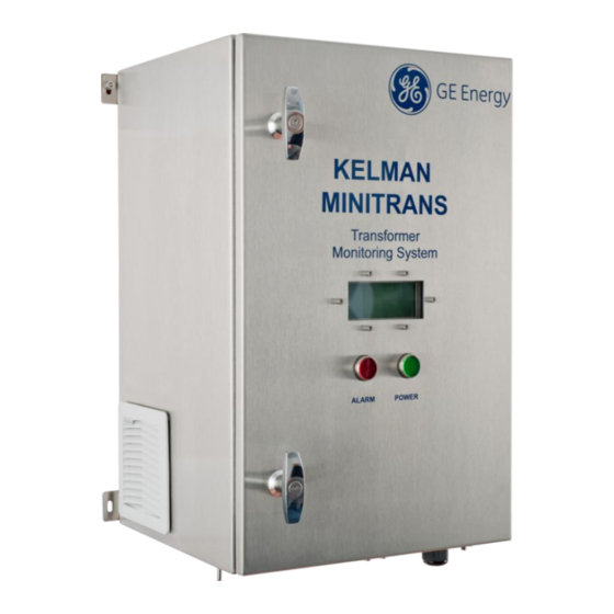
GE Kelman MINITRANS User Manual
Transformer oil dissolved gas and moisture monitor
Hide thumbs
Also See for Kelman MINITRANS:
- Operator's manual (26 pages) ,
- Installation manual (86 pages)

Related Manuals for GE Kelman MINITRANS


Summary of Contents for GE Kelman MINITRANS
- Page 1 Digital Energy Kelman MINITRANS ™ User Guide Transformer Oil Dissolved Gas and Moisture Monitor GEDE-GA_M-DLIS-SE.MA-006 Rev 2.1 13-Oct-15...
-
Page 2: Table Of Contents
Contents Introduction ............................ 4 Product Overview ........................4 Manual Scope ......................... 4 Safety .............................. 5 Symbols ..........................5 Warnings ..........................5 Hazardous Substances ......................6 Technical Specification ........................7 Design Criteria ..........................8 Power .............................. 9 Introduction ..........................9 LED status indicators ......................9 Battery .......................... - Page 3 Table of Figures Figure 5—1: Power switch ........................9 Figure 5—2: Fuse holder ........................9 Figure 5—3: Coin cell battery ....................... 10 Figure 6—1: Front view of the product ....................12 Figure 6—2: LCD information notice – error format (top) & example (below) ........12 Figure 6—3: Boot screen ........................
-
Page 4: Introduction
1 INTRODUCTION 1.1 Product Overview The MINITRANS™ (herein referred to as the product) is an on-line DGA (Dissolved Gas Analysis) system for transformer diagnostics. The product measures the following key fault gases in transformer oil: hydrogen, carbon monoxide and acetylene as well as moisture in the oil and the transformer load current. -
Page 5: Safety
The user shall also ensure that any third-party equipment, such as an approved platform, scaffold or lift is suitable and safe before commencing work. Ladders or improvised platforms do not meet GE service engineer requirements. Once installed, this product may have more than one source of supply. -
Page 6: Hazardous Substances
IP55 thresholds depending on the location, pressure and direction of the water jets. Therefore should customers require testing a water deluge system in the area in which the product is installed, GE recommends powering down the product and draping it with a suitable waterproof covering. -
Page 7: Technical Specification
10 metres or less from oil supply or return valve to product connection point, and on transformer oil supply valve volumes of 200ml or less. For oil temperatures colder than -10 ºC, GE recommends the use of heat trace cabling on piping. Note: Use only the approved and recommended fuse to ensure continued fire protection and compliance. -
Page 8: Design Criteria
4 DESIGN CRITERIA The product is designed to meet the following type tests as listed in Table 4—1: Table 4—1: Type tests Category Standard Class/Level Test EMC Emissions – CISPR 11 Radiated & Conducted Emissions EN 61326-1:2006 FCC Part 15 Radiated &... -
Page 9: Power
5 POWER 5.1 Introduction The product is powered up by pressing the Power switch located inside the product towards the bottom right-hand side (see Figure 5—1). The mains fuse holder for the product is shown in Figure 5—2. Note: The product automatically turns on the internal heaters to increase the internal temperature to within the PGA operational temperature range before a measurement can commence. -
Page 10: Battery
Figure 5—3: Coin cell battery The following steps describe how to change the battery: 1. Back up the product data – contact your GE representative. 2. Open the inner door to locate the battery on the system board (as shown in Figure 5—3). -
Page 11: Power-Down Procedure
5.4 Power-down procedure If the product needs to be powered down during shut down of the transformer, perform the following steps: 1. Observe the operating mode on the LCD. 2013-07-30 12:00:00 STANDBY 2. If the product is in Standby mode, perform the following steps: Open the door of the product and turn the power switch to the ‘Off’... -
Page 12: Lcd Display Panel
6 LCD DISPLAY PANEL The LCD display panel is visible through the door cut-out as shown in Figure 6—1. LCD display panel Figure 6—1: Front view of the product During an analysis, the display panel shows the serial number of the product and the operational state. -
Page 13: Example Information Screens
6.1 Example information screens The section outlines examples of the types of information notices and data pages rendered on the LCD display panel for a standard environment using factory settings. It illustrates typical information that a user is likely to see during normal operation. This can vary depending on the operational environment, firmware version and how the product is configured. -
Page 14: Manual Measurements
6.1.1.4 Peripheral Scheduler An information notice lists all peripheral connections as shown in Figure 6—7. If the peripheral scheduler is enabled, all analogue inputs are listed with corresponding null values. The product has analogue inputs AIn1 to AIn6, but corresponding values for these appear after peripheral(s) are connected. -
Page 15: Manual Oil Sampling
6.1.2.3 Measurement data The product automatically pages through the screens and measurement data of the last analysis. For example, data for the main tank is shown in Figure 6—10. Note: If nitrogen measurement is not enabled, the nitrogen and total gas concentration is omitted. MAIN LAST MEASUREMENT 2013-07-30 12:48:10... -
Page 16: Further System Specifications
6.1.4 Further system specifications 6.1.4.1 Communications channels The product has two serial communications channels. For example, default configuration details are shown in Figure 6—12, such as the interface, protocol, baud rate, modbus address and parity error-checking format: ChA RTU 1 RS232 19200 ChB: ASC 1 GSMGPRS... -
Page 17: Error Codes
6.2 Error Codes A list of error codes that can appear on the LCD display panel and their meaning are shown in Table 6—1. NOTE: Error codes are offset by 1 from the Modbus register bit numbers. Table 6—1: Error codes Error code Description Missing mains input... -
Page 18: Manual Oil Sampling
Perform the manual oil sampling according to the sampling process outlined in Figure 7— 4. GE recommends the use of a 50-ml ground glass syringe. Manual oil sampling shall be performed while the product is in Standby mode – either wait until the product returns to Standby mode or force the product to stop the current measurement cycle using the TransConnect software. -
Page 19: Sampling Process
7.2 Sampling Process Observe the PRODUCT operating mode on the LCD display panel. Figure 7—4 outlines the steps to obtain a manual oil sample. If the product is in Standby mode, Standby mode Measurement mode proceed to step 3. If the product is in Measurement mode, either wait until the product returns to Use TransConnect to stop... -
Page 20: Air Filter Cleaning
8 AIR FILTER CLEANING The product draws air from the left-hand side and expels it on the right. The intake air is filtered to remove the largest particles, so depending on environmental conditions the air filter as shown in Figure 8—1 and may need occasional cleaning. The outlet filter may also require attention. -
Page 21: Oil Filter Cleaning
9 OIL FILTER CLEANING The oil is filtered to prevent particles from entering the product, or to prevent particles from being returned to the transformer. Therefore this filter may need occasional cleaning. Figure 9—1 and Figure 9—2 show the oil filter housing and oil filter respectively. Note: A non-critical error in the product data file, such as error code 18 or 20 can be suggestive of such action. -
Page 22: Communications
PERCEPTION transformer monitoring software v1.12 or later. See the ‘Downloading service logs’ section in the PERCEPTION User Guide. 13 TECHNICAL SUPPORT For technical support, please contact the GE Customer Service Centre. Available 24 hours a day, 365 days a year. +1-800-361-3652 toll free (US/Canada) +1-514-420-7460 (worldwide) [email protected]... -
Page 23: Appendix A Time Sync Implementation
Appendix A Time Sync Implementation The product has a time-sync feature that allow users to synchronize the clock time on the product. This Appendix explains the data format options for the “time sync” and its implementation. Time Format Under the standard Modbus register list, the timing is defined in Table A—1: ®... -
Page 24: Table A-3: Access Flags
A.2.1 UNIX time format The number of seconds from the UNIX epoch time of 1st Jan 1970 00:00. A.2.2 UNIX time example For reference, the time on a device is reported in TransConnect as 12 Aug 2011 11:56:00 BST and the corresponding value in the registers mentioned above is 13146616. When testing, please check that you are reading registers 1197-1198 (assuming addresses start at 999 +1) and decoding an unsigned 32 bit big endian number. - Page 25 GE, the GE monogram, Kelman, TRANSFIX, MULTITRANS, TAPTRANS, and MINITRANS are trademarks of the General Electric Company. GE reserves the right to make changes to specifications of products described at any time without notice and without obligation to notify any person of such changes.