
Related Manuals for GE Kelman Minitrans


Summary of Contents for GE Kelman Minitrans
- Page 1 Grid Solutions Kelman™ Minitrans Operator Guide Transformer Oil Dissolved Gas and Moisture Monitor GEDE-GA_M-DLIS-TE.MA-006 Rev 2.2 5-Mar-20...
-
Page 2: Table Of Contents
Contents Page 1 Introduction ......................4 Product Overview ..............................4 Scope ..................................4 2 Safety ........................5 Symbols ..................................5 Safety Statements ............................... 5 Hazardous Substances ............................6 3 Technical Specification ..................7 4 Compliance ......................9 5 Power .........................10 Introduction ................................10 LED status indicators ............................10 Battery ..................................11... - Page 3 List of Tables and Figures Page Table 3-1: Technical specification ............................7 Table 4-1: Type tests ..................................9 Figure 5-1: Power switch ................................10 Figure 5-2: Fuse holder................................10 Table 5-1: External LED status indicators ........................10 Figure 5-3: Coin cell battery ..............................11 Figure 6-1: Front view of the product ..........................
-
Page 4: Introduction
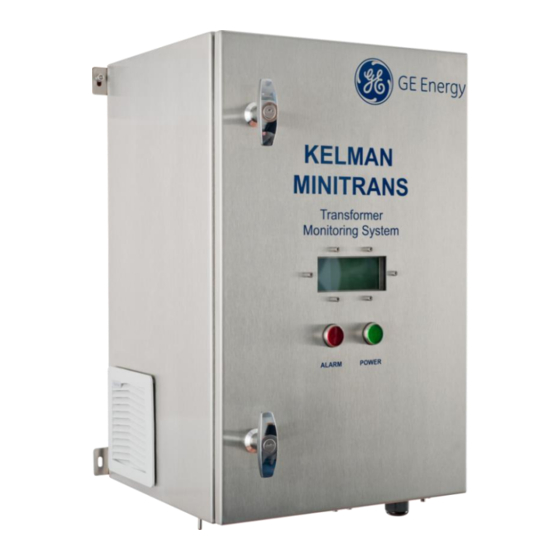
INTRODUCTION Product Overview The Minitrans™ (herein referred to as the product) is an on-line DGA (Dissolved Gas Analysis) system for transformer diagnostics. The product measures the following key fault gases in transformer oil: hydrogen, carbon monoxide and acetylene as well as moisture in the oil and the transformer load current. -
Page 5: Safety
SAFETY Symbols The meaning of symbols used on the Kelman™ Minitrans: Refer to the Installation Manual / Operator Guide to prevent death, injury, equipment damage or loss of data. Electrical Hazard. Risk of electric shock. Primary Protective Earth connection. Hot surfaces may be present. The meaning of symbols used in this manual: Warning: A procedure, practice, or condition could cause death or serious injury and/or significant equipment damage. -
Page 6: Hazardous Substances
IP55 thresholds depending on the location, pressure and direction of the water jets. Should customers require testing a water deluge system in the area in which the product is installed, GE recommends powering down the product and draping it with a suitable waterproof covering. -
Page 7: Technical Specification
10 metres or less from oil supply or return valve to product connection point, and on transformer oil supply valve volumes of 200 ml or less. For oil temperatures colder than −10 ºC, GE recommends the use of heat trace cabling on piping. Low oil viscosity reduces oil flow. - Page 8 Note: The weight depends on the order specification. The stated weight is for a base product without packaging and excludes options such as a mounting stand. Check the shipping document for the exact packaged weight. Note: Maximum DC breaking capacity for a resistive load. Note: Use only the approved and recommended fuse to ensure continued fire protection and compliance.
-
Page 9: Compliance
COMPLIANCE The product is designed to meet the following type tests as listed in Table 4-1. Table 4-1: Type tests CATEGORY STANDARD CLASS/ TEST LEVEL EMC Emissions CISPR 11 / EN55011 Radiated & Conducted Emissions IEC 61000-3-2 Harmonic Current Emissions Limits IEC 61000-3-3 Limitation of voltage changes, voltage fluctuations and flicker in public low-... -
Page 10: Power
POWER Introduction The product is powered up by pressing the Power switch located inside the product towards the bottom right-hand side (see Figure 5-1). The mains fuse holder for the product is shown in Figure 5-2. Note: The product automatically turns on the internal heaters to increase the internal temperature to within the PGA operational temperature range before a measurement can commence. -
Page 11: Battery
Figure 5-3: Coin cell battery The following steps describe how to change the battery: Back up the product data – contact your GE representative. Open the inner door to locate the battery on the system board (as shown in Figure 5-3). -
Page 12: Power-Down Procedure
Power-down procedure If the product needs to be powered down during shut down of the transformer, perform the following steps: Observe the operating mode on the LCD. 2013-07-30 12:00:00 STANDBY If the product is in Standby mode, perform the following steps: Open the door of the product and turn the power switch to the ‘Off’... -
Page 13: Lcd Display Panel
LCD DISPLAY PANEL The LCD display panel is visible through the door cut-out as shown in Figure 6-1. LCD display panel Figure 6-1: Front view of the product During an analysis, the display panel shows the serial number of the product and the operational state. -
Page 14: Lcd Information Notices
LCD Information Notices The section outlines some examples of the information notices and data pages rendered on the LCD display panel for a standard environment using factory settings. It illustrates typical information that a user is likely to see during normal operation. This can vary depending on the operational environment, firmware version and how the product is configured. -
Page 15: Manual Measurements
MAIN ????.?xxx Figure 6-7: Peripheral scheduler 6.1.2 Manual Measurements 6.1.2.1 Start a Manual Measurement Use TransConnect to start a manual measurement on the main tank. The timer automatically counts down from 10 seconds and indicates that a manual measurement is about to proceed. Figure 6-8 shows the relevant screens. MAIN MEASUREMENT IN 10 s... -
Page 16: Manual Oil Sampling
MAIN LAST MEASUREMENT 2019-07-30 12:48:10 MAIN MAIN 15220.0 ppm 1040.0ppm C2H2 2345.0 ppm 222.0ppm MAIN AIN 1 -1.111xxx MAIN NEXT MEASUREMENT 2019-07-30 16:48 Figure 6-10: Measurement data 6.1.3 Manual Oil Sampling If a manual oil sampling arrangement is fitted, perform the oil sampling according to the sampling process (see Section 7). - Page 17 XXX.XXX.XXX.XXX SUB: XXX.XXX.XXX.XXX GW: XXX.XXX.XXX.XXX TCP: 502 Figure 6-13: Networking 6.1.4.3 Other System Details Additional information notices reflect the configuration of the product. For example, if a GSM/GPRS modem is fitted, additional page(s) as shown in Figure 6-14 reflect the communications provider, signal strength and any problems.
-
Page 18: Error Codes
Error Codes The LCD panel error codes are listed in Table 6-1. Note: Error codes are offset by 1 from the Modbus register bit numbers. Note: This information relates to firmware version PGA 14.0.81 for Minitrans. Table 6-1: Error codes Code Error Note... -
Page 19: Manual Oil Sampling
Perform the manual oil sampling according to the sampling process outlined in Figure 7- 4. GE recommends the use of a 50-ml ground glass syringe. Manual oil sampling shall be performed while the product is in Standby mode – either wait until the product returns to Standby mode or force the product to stop the current measurement cycle using the TransConnect software. -
Page 20: Sampling Process
Sampling Process Observe the operating mode on the LCD display panel. Figure 7-4 and the accompanying steps detail the process to obtain a manual oil sample. If the product is in Standby mode, proceed to step 3. If the product is in Standby mode Measurement mode Measurement mode, either wait until... -
Page 21: Air Filter Cleaning
AIR FILTER CLEANING The product draws air from the left-hand side and expels it on the right. The intake air is filtered to remove the largest particles, so depending on environmental conditions the air filter as shown in Figure 8-1 and may need occasional cleaning. The outlet filter may also require attention. -
Page 22: Oil Filter Cleaning
OIL FILTER CLEANING The oil is filtered to prevent particles from entering the product, or to prevent particles from being returned to the transformer. Therefore, this filter may need occasional – cleaning. Figure 9-1 and Figure 9-2 show the oil filter housing and oil filter respectively. Note: A non-critical error in the product data file, such as error code 18 or 20 can be suggestive of such action. -
Page 23: Communications
Perception software v1.12 or later. See the ‘Downloading service logs’ section in the Perception User Guide. TECHNICAL SUPPORT For technical support, please contact the GE Customer Service Centre (24 hours a day, 365 days a year): T +44 1785-250-070 (United Kingdom) -
Page 24: Appendix A Time Sync Implementation
Appendix A Time Sync Implementation The product has a time-sync feature that allow users to synchronize the clock time on the product. This Appendix explains the data format options for the “time sync” and its implementation. Time Format Under the standard Modbus ®... - Page 25 A.2.3 Register Access Control The product registers are protected with access flags. The register map details the relevant access flags for each register. Each register may have one or more access flags, separated by commas. Table A-3 lists the supported access flags: Table A-3: Access flags Flag Access...
-
Page 26: Contact & Copyright Details
Other company or product names mentioned in this document may be trademarks or registered trademarks of their respective companies. GE reserves the right to make changes to specifications of products described at any time without notice and without obligation to notify any person of such changes.