
Related Manuals for Emerson NZ Series


Summary of Contents for Emerson NZ Series
- Page 1 Instruction Manual D103764X012 January 2022 NZ/NZ-M and NZOS/NZOS-M Series Pressure Reducing Regulators...
-
Page 2: Table Of Contents
Emerson Regulators must be installed, operated and maintained in accordance with federal, state and local codes, rules and regulations and by strictly following instructions by Emerson Process Management Asia Pacific Pte Ltd, Regulator Technologies. -
Page 3: Introduction
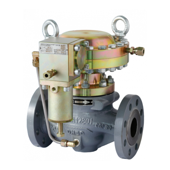
NZ/NZ-M and NZOS/NZOS-M Series Introduction Scope of the Manual This instruction manual provides installation, startup and maintenance instructions and parts ordering information for the NZ/NZ-M and NZOS/NZOS-M Series pressure-reducing regulators and JP Series pilots. Information on other equipment used with this regulator is found in separate manuals. Description Type NZ/NZ-M is a pilot-operated pressure regulator designed for high pressure transmission, power plant skids, city gate stations, large capacity gas distribution systems, CNG stations, industrial skids and commercial installations. - Page 4 NZ/NZ-M and NZOS/NZOS-M Series Body Sizes, End Connection Styles and Pressure Rating See Table 1 Maximum Allowable Pressure 102 bar / 1479 psig Emergency Casing Pressure: 102 bar / 1479 psig See Table 3 Minimum Differential Pressure Accuracy Class (Regulating Device): Up to AC 1 Accuracy Class (Slam Shut): Up to AG 1...
-
Page 5: Principle Of Operation
NZ/NZ-M and NZOS/NZOS-M Series Table 3. Minimum Differential Pressure MINIMUM DIFFERENTIAL MAIN VALVE BODY SIZE PRESSURE START OPEN FULL OPEN SERIES RATING ANSI 150 7.25 11.6 ANSI 300 ANSI 600 17.4 ANSI 150 7.25 11.6 ANSI 300 ANSI 600 17.4 ANSI 150 17.4 ANSI 300... - Page 6 NZ/NZ-M and NZOS/NZOS-M Series Working Monitoring Systems In a working monitoring system, the upstream regulator requires two pilots and it is always the monitoring regulator. The additional pilot permits the monitoring regulator to act as a series regulator to control an intermediate pressure during normal operation.
-
Page 7: Installation
NZ/NZ-M and NZOS/NZOS-M Series Figure 5. Type NZ Working Monitor System Operational Schematic WORKER MONITOR PILOT PILOT INLET PRESSURE PILOT SUPPLY PRESSURE OUTLET PRESSURE ATMOSPHERIC PRESSURE LOADING PRESSURE INTERMEDIATE PRESSURE MONITOR REGULATOR WORKING REGULATOR Figure 6. Type NZOS Working Monitor System Operational Schematic WORKER MONITOR PILOT... - Page 8 NZ/NZ-M and NZOS/NZOS-M Series All Installations An NZ/NZ-M or NZOS/NZOS-M Series regulator bleeds no gas to atmosphere during normal operation, making it suitable for installation in pits and other enclosed locations without elaborate venting systems. This regulator also can be installed in pits subject to flooding by venting the pilot spring case above the expected flood level so that the pilot diaphragm is always ...
-
Page 9: Adjustment
NZ/NZ-M and NZOS/NZOS-M Series 1. Follow the procedure in the All Installations section, and then continue with step 2 of this section. The sense line of the upstream monitor pilot and the bleed and sense lines of the downstream pilot will be connected to the downstream piping (see Figures 5 and 6). -
Page 10: Shutdown
NZ/NZ-M and NZOS/NZOS-M Series For a wide-open monitor installation (Figures 3 and 4), adjust the working pilot to a set point higher than the set point of the monitor pilot. Adjust the monitoring pilot to the desired monitoring takeover pressure. Reduce the pilot to the normal outlet pressure setting. - Page 11 NZ/NZ-M and NZOS/NZOS-M Series 5. Set the seat (key 2) back in the body (key 1). Place the cage (key 4) on top of seat. Then place sleeve guide (key 5) on top of cage. 6. Insert ring snap (key 32) into the groove between body (key 2) and sleeve guide (key 5). Lightly lubricate O-rings (keys 22 and 33) and put them back.
- Page 12 NZ/NZ-M and NZOS/NZOS-M Series Wide-Open Monitoring Balance Stem Assembly Maintenance (refer to Figure 7) 1. Remove travel indicator assembly according travel indicator maintenance section if an indicator has been installed. 2. Loose male connector (key 75), remove sensing line (key 132). 3.
-
Page 13: Parts Ordering
NZ/NZ-M and NZOS/NZOS-M Series JPLC and JPHC Series Second Stage Maintenance (refer to Figure 11) 1. Loose locknut (key 73) and back out adjusting screw (key 71) until compression is removed from the spring. 2. Loose spring cover (key 74), then take out spring seat (key 35) and spring (key 36). 3. - Page 14 NZ/NZ-M and NZOS/NZOS-M Series Description Description Sensing Line JP Series Pilots (Figures 10 and 11) Name Plate Upper Spring Seat Plug Spring Stem Connector Support Screw Side Cover Indicator Cover Disk Indicator Fitting Spring Cover Indicator Stem Orifice Indicator Bushing Spring Indicator Connector Filter...
- Page 15 NZ/NZ-M and NZOS/NZOS-M Series Table 4. NZ Main Valve Torque Specifications NZ/NZ-M SERIES MAIN VALVE TORQUE SPECIFICATIONS (N•m) PART NAME DN 25 / NPS 1 DN 50 / NPS 2 DN 80 / NPS 3 DN 100 / NPS 4 DN 150 / NPS 6 Diameter Torque...
- Page 16 NZ/NZ-M and NZOS/NZOS-M Series Figure 7. NZ Series Main Valve Assembly ALL SIZE ANSI 600 6" ANSI 300 O-RING RETAINER DETAIL 1" ACTUATOR INSIDE DETAIL TYPE NZ VIEW A TYPE NZ-M WIDE-OPEN MONITORING VERSION...
- Page 17 NZ/NZ-M and NZOS/NZOS-M Series Figure 7. NZ Series Main Valve Assembly (continued) VERSION WITH INDICATOR INDICATOR DETAIL VERSION WITH TRAVEL INDICATOR...
- Page 18 NZ/NZ-M and NZOS/NZOS-M Series Figure 7. NZ Series Main Valve Assembly (continued) VERSION WITH TRANSDUCER DETAIL K VERSION WITH LINER TRANSDUCER...
- Page 19 NZ/NZ-M and NZOS/NZOS-M Series Figure 8. NZ Series Pilot Mounting Assembly NZ WITH JPLO/JPHO PILOT NZ WITH JPLC/JPHC PILOT JPLO/JPHO/JPLC/JPHC PILOT NZ MAIN VALVE INLET DN 25 THROUGH 100 / NPS 1 THROUGH 4...
- Page 20 NZ/NZ-M and NZOS/NZOS-M Series Figure 8. NZ Series Pilot Mounting Assembly (continued) NZ WITH JPLO/JPHO PILOT NZ WITH JPLC/JPHC PILOT JPLO/JPHO/JPLC/JPHC PILOT NZ MAIN VALVE INLET DN 150 / NPS 6...
- Page 21 NZ/NZ-M and NZOS/NZOS-M Series Figure 9. NZ Series Working Monitor Mounting Assembly NZ WITH JPLCM/JPLCW PILOT NZ WITH JPLCM/JPLCW PILOT INLET INLET NZ MAIN VALVE SUPPLY P1 TO WORKING MONITOR WORKING PILOT MONITOR PILOT...
- Page 22 NZ/NZ-M and NZOS/NZOS-M Series Figure 10. JPHO/JPLO, JPHOM/JPLOM and JPHOW/JPLOW Series Pilot Assembly HIGH PRESSURE SECOND STAGE DIAPHRAGM ASSEMBLY DETAIL FOR TYPE JPHO/JPHOW/JPHOM MONITOR PILOT SECOND STAGE ORIFICE ASSEMBLY DETAIL FOR TYPE JPHOM/JPLOM WORKER PILOT FIRST STAGE ASSEMBLY DETAIL FOR TYPE JPHOW / JPLOW TYPE JPHOW/JPLOW TYPE JPHO/JPLO TYPE JPHOM/JPLOM...
- Page 23 NZ/NZ-M and NZOS/NZOS-M Series Figure 11. JPHC/JPLC, JPHCM/JPLCM and JPHCW/JPLCW Series Pilot Assembly HIGH PRESSURE APPLICATION SECOND STAGE DIAPHRAGM ASSEMBLY DETAIL FOR TYPE JPHC/JPHCW/JPHCM MONITOR PILOT SECOND STAGE ORIFICE ASSEMBLY DETAIL FOR TYPE JPHCM/JPLCM WORKER PILOT FIRST STAGE ASSEMBLY DETAIL FOR TYPE JPHCW / JPLCW TYPE JPHCW/JPLCW TYPE JPHC/JPLC...
- Page 24 Jeon is a mark owned by one of the businesses of Emerson Automation Solutions. All other marks are the property of their respective owners. The contents of this publication are presented for informational purposes only, and while every effort has been made to ensure their accuracy, they are not to be construed as warranties or guarantees, express or implied, regarding the products or services described herein or their use or applicability.