Table of Contents
Quick Links
SX-M100
J
U
EK 51001 and Higher
SX-M700
J
U
EK 51001 and Higher
11001 and Higher
21001 and Higher
11011 and Higher
21001 and Higher
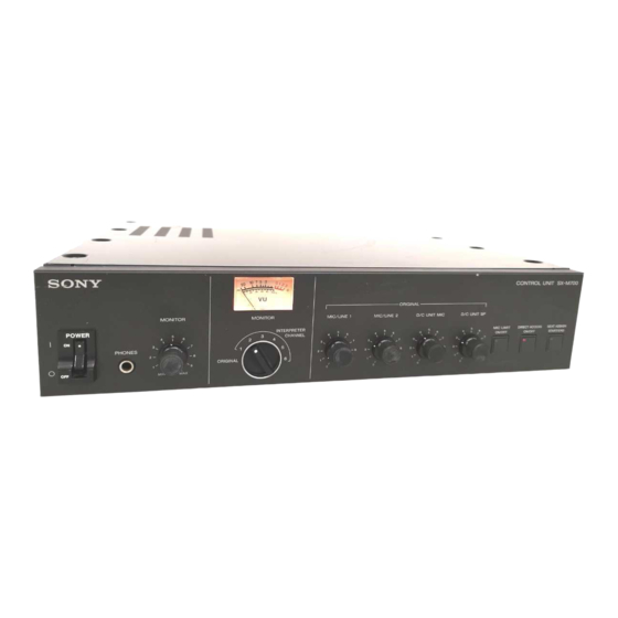
CONTROL UNIT
SX-M700
SX-M100
EXPANSION UNIT
SX-E120
EXPANSION BOARD
SXA-120
TELEPHONE COUPLER
SX-T100
SERVICE MANUAL
2nd Edition
SX-E120
SX-T100
SXA-120
J
11001 and Higher
U
21001 and Higher
EK 51006 and Higher
10001 and Higher
11001 and Higher
Chapters
Table of Contents
Troubleshooting

Related Manuals for Sony SX-M700


Summary of Contents for Sony SX-M700
- Page 1 CONTROL UNIT SX-M700 SX-M100 EXPANSION UNIT SX-E120 EXPANSION BOARD SXA-120 TELEPHONE COUPLER SX-T100 SERVICE MANUAL 2nd Edition SX-M100 11001 and Higher SX-E120 11001 and Higher 21001 and Higher 21001 and Higher EK 51001 and Higher EK 51006 and Higher SX-M700...
-
Page 2: Table Of Contents
4-2-3. Check Points in Case of Error ....4-3(E) 2-2. Board Locations ..........2-4(E) (Assuming That the Input and 2-3. Board Removal (SX-M700/M100/E120) ..2-6(E) Output Stages are Normal) ....... 4-3(E) 2-3-1. Removal of the PS-364 Board ....2-6(E) 4-3. Self Diagnostics of CPU-181 Board ....4-4(E) 2-3-2. - Page 3 8. BLOCK DIAGRAMS SX-M700/M100 DIGITAL ........8-1 SX-M700 AUDIO ..........8-2 SX-M100 AUDIO ..........8-3 SX-E120 DIGITAL ..........8-4 SX-E120 AUDIO ..........8-5 SX-T100 AU-202 ..........8-6 SXA-120 AUDIO ..........8-7 9. BOARD LAYOUTS AND SCHEMATIC DIAGRAMS AA-79/79X ............9-2 AA-93/93X ............
-
Page 4: Operating Instructions
SECTION 1 This section is extracted OPERATING INSTRUCTIONS from operation manual. SX-M700 1-1(E) - Page 5 The model and serial numbers are located on the rear of communications. Operation of this equipment in a Outline ......................4 the SX-M700 and on the bottom of the SX-C700A/C750/ residential area is likely to cause harmful interference in Features ....................4 D700A/D750/P700/T100.
- Page 6 When the SX-S100 microphone control panels are used, they are connected using only the connecting cables. For detailed information on the power interface unit, contact your Sony dealer. • Personal computer For details of the SXA-120 Expansion Board, refer to the manual supplied with the...
- Page 7 Location and Function of Parts and Controls 5 Level meter 8 DIRECT ACCESS ON/OFF button SX-M700 Control Unit Indicates the output level of the audio signal This button is effective only when the SXA-120 selected by the MONITOR channel selector 4.
- Page 8 Location and Function of Parts and Controls !¢ EXT IN-2 MIC/LINE (external 2 microphone/ MIC/LINE switch SX-C700A/C750/SX-D700A/D750 Chairman’s Unit/Delegate’s Unit line signal input) connectors and MIC/ Selects the signal input to the EXT IN-1 connector. MIC: Set the switch to this position when a LINE (microphone/line signal select) microphone is connected.
- Page 9 9 CH (channel) selector Connect to the DELEGATE’S/CHAIRMAN’S Select the signal to be output to the earphone jack UNIT connector of the SX-M700 Control Unit, and the REC OUT connector. You can select either SX-E120 Expansion Board (not supplied) or the the original signal, or channel 1 to channel 6.
- Page 10 (5m or 16.4 feet/10m or 32.8 feet) (not supplied). When the interpreter’s unit is MICROPHONE OFF button RELAY button and ORIGINAL button placed next to the SX-M700 Control Unit, connect When the RELAY button is pressed, it lights and MICROPHONE ON button SLOW button to the INTERPRETER’S UNIT connector of the...
- Page 11 In case of malfunctions If you notice any unusual sound, smell or smoke, turn off the power immediately, disconnect the power supply and contact your Sony dealer. CONTROL UNIT connector Cleaning Clean the cabinet and panels by wiping with a soft, dry cloth. For severe stains,...
- Page 12 • Do not set the POWER switch of the SX-M700 to ON again promptly after the POWER switch is set to OFF. If you do so, the power of the SX-M700 may not be turned on, or the software built in the SX-M700 may not start. Be sure set the...
- Page 13 Setting Up the System Assigning Interpreted Languages to Channels How to connect cables of SX-C700A/D700A The figure below shows how to connect and disconnect the 20-pin multi- connectors of the chairman’s/delegate’s unit, RK-1700/1705 and RK-1710/1713 Assign the interpreted languages to the channels (1 to 6) of the interpreter’s units connecting cables.
- Page 14 Setting Up the System Adjusting the input level of the audio signal from equipment Preparing the Control Unit connected to EXT IN-1/2 connectors Adjusting the audio level Rear of the control unit Adjust the audio signal output to the chairman’s/delegate’s unit from external equipment connected to EXT IN-1/2 before the conference.
- Page 15 http://getMANUAL.com Operation During a Conference Operations Performed by the Chairman and Delegates Interpreter’s Operations Operations common to both the chairman and delegates An interpreter uses an SX-P700 interpreter’s unit. The interpreter’s unit is designed to be used simultaneously by two interpreters. The chairman and delegates can both talk and listen by using their individual unit.
- Page 16 Operation During a Conference MICROPHONE OFF button and the SLOW button are common to left and right Taking Part in a Conference via the Telephone blocks of the interpreter’s unit. Either of the two interpreters can use these buttons. A person can take part in a conference from a remote location by using the SX-T100 Telephone Coupler .
- Page 17 If the system continues to malfunction after and MIC ON/OFF button Possible cause Remedies applying the following checks and remedies, contact your nearest Sony dealer. of the chairman’s unit/ The system indicates the problem by lighting the microphone indicator and MIC delegate’s unit ON/OFF button of chairman’s/delegate’s units.
- Page 18 Earphone output (minijack) ×2 Design and specifications are subject to change Output REC OUT (minijack)×1 without notice. Output level 250 mV (–10dBs), SX-M700 Control Unit load impedance 47 kilohms Input/output DELEGATE’S /CHAIRMAN’S Microphone line UNIT (20-pin multi-connector) ×4 Output level 250 mV (–10dBs) INTERPRETER’S UNIT (20-pin...
- Page 19 3-759-749-13 (1) Conference System Model: SX-M100 Control Unit SX-C100A/SX-C150 Chairman’s Unit SX-D100A/SX-D150 Delegate’s Unit SX-T100 Telephone Coupler Operating Instructions Before operating the unit, please read this manual thoroughly and retain it for future reference. © 1994 by Sony Corporation...
- Page 20 System Configuration ................5 provided below. Refer to them whenever you call upon interference at his own expense. your Sony dealer regarding these products. You are cautioned that any changes or modifications not Location and Function of Parts and Controls .......... 6 Model No.
-
Page 21: Outline
When the SX-S100 microphone control panels are used, they are connected using only the connecting cables. For detailed information on the power interface unit, contact your Sony dealer. • Personal computer For details of the SXA-120 Expansion Board, refer to the manual supplied with the... -
Page 22: Location And Function Of Parts And Controls
Location and Function of Parts and Controls 1 POWER switch MIC (microphone) LIMIT ON: Press this button SX-M100 Control Unit to set the microphone to the speaker’s number Setting the switch to ON (1) turns the power on. The level meter will light. limitation mode. -
Page 23: Sx-C100A/C150/Sx-D100A/D150 Chairman's Unit/Delegate's Unit
Location and Function of Parts and Controls 0 EXT IN-1 MIC/LINE (external 1 microphone/ !¢ DELEGATE’S/CHAIRMAN’S UNIT SX-C100A/C150/SX-D100A/D150 Chairman’s Unit/Delegate’s Unit line signal input) connectors and MIC/LINE connectors (20-pin multi-connectors) switch Connect to the SX-C100A/SX-C150/SX-D100A/ EXT IN-1 MIC/LINE connectors SX-D150 Chairman’s Unit/Delegate’s Unit. The The following two combinations of the chairman’s unit and delegate’s unit are Accept an external audio signal. - Page 24 (not supplied). MIC ON/OFF button and For SX-C150/SX-D150 (D-sub 15-pin) For details, contact your Sony dealer. indicator Connect to the input connector on the next 7 PRIORITY button and indicator (for the chairman’s unit and delegate’s unit.
-
Page 25: Sx-T100 Telephone Coupler
http://getMANUAL.com Location and Function of Parts and Controls When the MIC ON/OFF button of the SX-T100 Telephone Coupler delegate’s unit is pressed under the condition where the PRIORITY button of the chairman’s unit is held down, the MIC ON/OFF button indicator and microphone indicator blink for about 3 seconds to tell the user that the microphone cannot be enabled. -
Page 26: Setting Up The System
It is not recommended to mix both combinations. turn off the power immediately, disconnect the • When the SX-C100A/D100A is used, the SX- Cable with 20-pin power supply and contact your Sony dealer. multi-connector to output C700A/C750/D700A/D750 Chairman’s Unit/ connector Delegate’s Unit, designed for the simultaneous... -
Page 27: Turning On The Power Of The System
Setting Up the System Turning On the Power of the System Preparing the Control Unit Adjusting the audio level Control unit Adjust the audio signal output to the chairman’s/delegate’s unit and input from the external equipment connected to EXT IN-1/2 before the conference. ORIGINAL MONITOR MIC/LINE 1... -
Page 28: Operation During A Conference
Operation During a Conference Setting Up the System Adjusting the input level of the audio signal from equipment Operations Performed by the Chairman and Delegates connected to EXT IN-1/2 connectors Operations common to both the chairman and delegates Rear of the control unit The chairman and delegates can both talk and listen by using their individual unit. -
Page 29: Taking Part In A Conference Via A Telephone
Taking Part in a Conference via a Telephone instructions in the table below. If the system continues to malfunction after applying the following checks and remedies, contact your nearest Sony dealer. A person can take part in a conference from a remote location by using the The system indicates the problem by lighting the microphone indicator and MIC SX-T100 Telephone Coupler . - Page 30 Specifications SX-M100 Control Unit SX-C100A/SX-C150 Chairman’s Unit SX-D100A/SX-D150 Delegate’s Unit Input/output connectors Earphone output (minijack) ×2 Output DELEGATE’S /CHAIRMAN’S UNIT (20-pin multi-connector) ×4 REC OUT (minijack)×1 TELEPHONE COUPLER (6-pin Output level 250 mV (–10dBs), multi connector ) ×1 load impedance 47 kilohms Power requirements Input EXT IN-1/EXT IN-2...
- Page 31 1 Removal of the Top Panel Screw “a” (5 pcs) B 3x6 1. Remove the ten fixing screws “a” (B 3x6 TYPE 2). TYPE 2 2. Remove the top panel in the direction of arrow A. Screw “a” (5 pcs) B 3x6 TYPE 2 Screw “e”...
- Page 32 1 Removal of the Top Panel Screw “a” (5 pcs) 1. Remove the ten fixing screws “a” (B 3x6). B 3x6 2. Remove the top panel the direction of arrow A. TYPE 2 Screw “a” (5 pcs) B 3x6 TYPE2 Screw “f”...
- Page 33 2. Remove the two fixing screws “a” (PTP 3x8), then remove the acoustic coupler. 3 Removal of the RP-type 6-pin Connector 1. Disconnect the connector (CN2) from the SW-704 board. 2. Unscrew the four screws “b” (PTP 2.6x6), then disconnect the RP-type 6-pin connector. SX-M700 2-3(E)
- Page 34 5 HP-65 board 6 MT-105 board 7 PS-363 board 8 PS-364 board 9 SW-710 board 0 SW-722 board (SX-M700 ONLY) !- SW-723 board (SX-M700 ONLY) != VR-233 board ![ CN-1478 board !] TR-107 board !\ AC-190 board (J, EK only)
- Page 35 SX-E120 INDEX 1 AL-31 board 2 CPU-181 board 3 DU-3 board 4 PS-363 board 5 PS-364 board 6 AC-190 board (J, EK only) SX-T100 INDEX 1 AU-202 board 2 SW-704 board SX-M700 2-5(E)
-
Page 36: Removal Of The External Panels
2-3. BOARD REMOVAL (SX-M700/M100/E120) Caution : Before removing the boards, be sure to turn off the main power. 2-3-1. Removal of the PS-364 Board SX-M700/M100 Procedure 1. Remove the top panel. (Refer to section, “2-1. REMOVAL OF THE EXTERNAL PANELS”.) 2. - Page 37 (from AL-31 board) Connector CN908 Screws (3 pcs) (from CPU-181 board) Connector CN904 PSW 3x8 (from AL-31 board) Connector CN906 (from power lamp) Screws (3 pcs) PSW 3x8 Connector CN907 (from AL-31 board) PS-364 board Connector CN903 Harness clamp SX-M700 2-7(E)
-
Page 38: Removal Of The Cpu-181 Board
2-3-2. Removal of the CPU-181 Board SX-M700/M100 Procedure 1. Remove the top panel. (Refer to section, “2-1. REMOVAL OF THE EXTERNAL PANELS”.) 2. Disconnect the three connectors (CN3, CN4, CN5) from the CPU-181 board. 3. Remove the five screws (PSW 3x8), then remove the CPU-181 board. - Page 39 3. Remove the five screws (PSW 3x8) then remove the CPU-181 board. Connector CN2 (from AL-31 board) Connector CN5 Connector CN3 (from AA-93 board) (from PS-364 board) Screws (3 pcs) PSW 3x8 Screws (2 pcs) PSW 3x8 CPU-181 board SX-M700 2-9(E)
-
Page 40: Removal Of The Aa-93 Board (Sx-M700/M100)
2-3-3. Removal of the AA-93 Board (SX-M700/M100) Required Tools : Nutdriver (7 mm) Procedure Sony Part No. : 7-700-751-06 1. Remove the top panel. (Refer to section, “2-1. REMOVAL OF THE EXTERNAL PANELS”.) 2. Remove the CPU-181 board. (Refer to section, “2-3-2. -
Page 41: Removal Of The Al-31 Board (Sx-E120)
2-3-4. Removal of the AL-31 Board (SX-E120) Required Tools : Nutdriver (7 mm) Procedure Sony Part No. : 7-700-751-06 1. Remove the top panel. (Refer to section, “2-1. REMOVAL OF THE EXTERNAL PANELS”.) 2. Remove the CPU-181 board. (Refer to section, “2-3-2. -
Page 42: Removal Of The Hp-65 Board (Sx-M700/M100)
2-3-5. Removal of the HP-65 Board (SX-M700/M100) 2-3-7. Removal of the VR-237 Board (SX-M700/M100) Procedure Procedure 1. Remove the top panel. (Refer to section, “2-1. 1. Remove the top panel. (Refer to section, “2-1. REMOVAL OF THE EXTERNAL PANELS”.) REMOVAL OF THE EXTERNAL PANELS”.) 2. -
Page 43: Installation Of The Expansion Board (Sxa-120)
2-4. INSTALLATION OF THE EXPANSION BOARD (SXA-120) . The expansion board SXA-120 (option) can be attached CPU-188 Board Main Unit (SX-M700/M100) to the SX-M700 and SX-M100. (SXA-120) To CN1 of CPU-181 board Procedure To CN20 of AA-93 board 1. Remove the top panel. (Refer to section, “2-1. -
Page 44: Removal Of The Velcro Fastener Tape (Sx-T100)
2. Remove the Velcro fastener tape. Cabinet assembly Velcro fastener tape Outer toothed Screw washer 3 mm Screw PTP 3x6 PTP 3x6 Outer toothed washer 3 mm Screw PTP 3x6 Outer toothed Screw washer 3 mm PTP 3x6 2-14(E) SX-M700... -
Page 45: Rack Mount
2-6. RACK MOUNT The SX-M700, SX-M100 and SX-E120 can be attached to the EIA standard 19-inch rack using the following angles: Parts required : Rack angle assembly 2 pcs (A-8310-721-A) Screw B 4x10 8 pcs (7-682-562-09) Screw RK 5x10... -
Page 46: Connector Input And Output Signals
2-7. CONNECTOR INPUT AND OUTPUT SIGNALS SX-M700/M100/E120 SX-M700 ONLY DELEGATE’ S/CHAIRMAN’ S UNIT 1 ~ 4 INTERPRETER’ S UNIT 1/2 (5 ~ 8 for SX-E120) (Used only in SX-M700) PR13A type, 20 pin PR13A type, 20 pin -OUTSIDE VIEW- -OUTSIDE VIEW- Signal Name IN/OUT... - Page 47 SX-M700/M100 ONLY SX-E120 ONLY EXT IN-1 CONTROL UNIT PUSH XLR 3 pin, female, balanced (Used only in SX-E120) -OUTSIDE VIEW- PR13A type, 20 pin -OUTSIDE VIEW- Signal Name IN/OUT Description Signal Name IN/OUT Description –––– –––––––- ORG IN ORIGINAL audio signal...
-
Page 48: Switch Setting
2-8. SWITCH SETTING Set up the BIT switch on the CPU-181 board Factory default settings SX-M700 SX-M100 SX-E120 2-9. POWER CORD (SUPPLIED) J: 1-534-754-00 AC inlet (Control Unit) U: 1-551-812-11 AC inlet (Control Unit) EK: 1-590-910-11 AC inlet (Control Unit) -
Page 49: Safety Check-Out
Equipment intended for connection to a 3-wire, grounded neutral power supply, as illustrated above. A. Probe with shielded lead. B. Separated and used as clip when measuring currents from one part of equipment to another. SX-M700 2-19(E) -
Page 50: System Configuration And Circuit Description
SYSTEM CONFIGURATION AND CIRCUIT DESCRIPTION 3-1. SYSTEM CONFIGURATION SX-M700 ----Simultaneous Translation System ---- Telephone Coupler Unit SX-T100 4 D/CU Connection Cable (5 m) supplied Control Unit SX-M700 Channels SONY Pig-tail cable Pig-tail cable RK-1710 (10 m) RK-1713 (3 m) 15 units maximum... -
Page 51: Circuit Descriptions
The audio signals are passed through the digital block. interpreter’s unit (IPU). When the SLOW signal is created, the microprocessor issues the blinking command The DC 24V power supply in the SX-M700/M100 and the to the chairman’s unit. other DC 24V from the SX-E120 are output to the microphone control units. -
Page 52: Audio Block
SX-M700 . D/CU 1 . D/CU 2 The audio block of the SX-M700 has the following basic . D/CU 3 functions. . Receiving the audio signal from chairman and delegate units, . D/CU 4 . - Page 53 These input signals are passed through the limiter and The audio block of the SX-M100 is equivalent to that of mixer, amplitude-adjusted by the MASTER volume the SX-M700 except that the circuit for the IPU control, passed through a band-pass filter and feed the (interpreter’s unit) is eliminated.
-
Page 54: Troubleshooting
When the main power was turned on, the self-check detected that (Blinks repeatedly) the D/C units could not establish communication. (The micro processor is not receiving the self-check data.) ERROR 4 Communication has aborted without establishing communication (Blinks repeatedly) while in normal communication mode. SX-M700 4-1(E) -
Page 55: Troubleshooting Procedure
4-2-2. If Error-1 to Error-3 Occurs in a Single Unit Unit A Unit B Unit C Control Unit Cable A Cable B Cable C The cause of the trouble may be located in one of the following: Processing stage of unit B 4-2(E) SX-M700... -
Page 56: Check Points In Case Of Error
. Signal path from IC504 to IC505 . IC505 3. Error-4 Error-4 may be caused by a software problem. If Error-4 occurs frequently, there may be a hardware problem such . Signal path from IC505 to IC504 . IC505 SX-M700 4-3(E) -
Page 57: Self Diagnostics Of Cpu-181 Board
LED blinks. *D/C units : Delegate and Chairman’s Units 2 To enable the SIO check of the SX-M700/M100 to be 4-3-4. Factory Default Settings performed, short pins 1 and 2, and pins 3 and 4 of CN1. -
Page 58: Self Diagnostics Of Cpu-188 Board
D1 to D4 turn on as the above steps proceed. If an error lower significant bit settings. Check the factory default occurs, D1 to D4 blink and the check terminates. If no settings when installing the SX-M700 and SX-M100 on errors occur, LEDs D1 to D8 turn on. site. -
Page 59: Self Diagnostics Of Sx-C700/C100/D700/D100
6. EP ATT ON 7. EP ATT OFF 8. Channel selector ON 9. Channel selector OFF 10. Speaker OFF The respective control system can be checked using a single D/C unit by observing the results of operating the above sequence. 4-6(E) SX-M700... -
Page 60: Electrical Alignment
. Audio Signal Generator : HP 8904 or equivalent . Digital Voltmeter : Advantest TR6845 or equivalent . Frequency Counter : Advantest TR582AK or equivalent 5-2. LOCATIONS OF PARTS (SIDE A) PS-364 Board CN904 TP904 CN905 RV901 TP903 CN908 RV902 CN907 HP-65 Board SX-M700 5-1(E) -
Page 61: Connecting Diagram
. Adjust RV901 so that the switching frequency satisfies the . Connect a frequency counter to specification. the measurement point. . Turn on the main power. Frequency RV901 high ± Switching frequency : 100 1 kHz 5-2(E) SX-M700... -
Page 62: Output Voltage (Ps-364 Board) Adjustment
Specification : +24 V CN907 CN908 Pin No. Specification Pin No. Specification _5 V +5 V +5 V +5 V +24V Confirm that the output voltage at the respective pins of CN904, CN905, CN907 and CN908 satisfies the specifica- tion. SX-M700 5-3(E) -
Page 63: Vu Meter Adjustment
MASTER / front panel scale “7” position. Output at the connector= _10 dB STEP-2 VU meter/front panel 1 RV2/HP-65 Board Make adjustment so that the meter pointer stays at 0 VU. 5-4(E) SX-M700... -
Page 64: Semiconductor Pin Assignments
TC74AC163F ........6-9 TC74AC32F ........6-10 TC74AC74F ........6-10 TC74HC04AP ........6-8 TC74HC07AF ........6-11 TC74HC4053AP ....... 6-11 TC74HC4094AP ....... 6-11 TMP68301AFR-16 ......6-12 TMP82C51AM ........6-13 UPC1093J ......... 6-13 UPC1094C ........6-13 UPC24M06HF ........6-8 UPC4572C ........6-13 SX-M700... - Page 65 LR002-01 IL00 ********** TR011-02 IL00 SEL2311G;GREEN TYPE NO. ********** PRINTED 2SC2785 2SD1020 2SD1021 ********** ERB81-004 ES1F 2SK792 TLR211;RED LR029-01 IL00 RD6.2ESB2 RD16ESB1 ***** GL8HD22;RED TR002-04 IL08 ***** 2SK975 TLP521-2 DA001-02 IL00 ********** MA7120 MA7270 RD13ESB1 RD16EBS1 RD6.2ESB2 RD6.2FB2 RY-24 SX-M700...
- Page 66 ; HIGH LEVEL ; DON'T CARE EP330PC-15(ALTERA) CXK58257SP-10L (2/2) DECODER BUFFER MEMORY MATRIX 512 x 512 I/O 8 I/O 7 I/O 6 I/O GATE I/O 5 BUFFER COLUMN BUFFER I/O 4 DECODER I/O 3 I/O 2 I/O 1 BUFFER SX-M700...
- Page 67 — — — — — GCLK/IN OE1/IN — — LT1081CN(LINEAR TECHNOLOGY) EPM7032LC44-3(2/2) GCLK GCLR/IN OE1/IN OE2/IN GCLK/IN GCLR/IN OE1/IN OE2/IN 24-29 31-34 11-14 36-41 16-21 CONTROL MACROCELL MACROCELL CONTROL BLOCK BLOCK (1-16) (17-32) ABOVE DIAGRAM SHOWS CONDITIONS BEFORE PROGRAMMING SX-M700...
- Page 68 RS232C DRIVERS/RECEIVERS -TOP VIEW- (+5V) DRIVER DRIVER DRIVER DRIVER DRIVER DRIVER DRIVER DRIVER INPUT DRIVER ;RS-232C DRIVER INPUTS ;RECEIVER INPUTS OUTPUT DRIVER ;RS-232C DRIVER OUTPUTS ;RECEIVER OUTPUTS TTL/CMOS VOLTAGE LEVELS C1+,C1-,C2+,C2- ;EXTERNAL CAPACITORS ;POSITIVE SUPPLY(RS-232C DRIVERS) ;NEGATIVE SUPPLY(RS-232C DRIVERS) SX-M700...
- Page 69 ; OUTPUT ENABLE INPUT ; OUTPUT ENABLE INPUT ; WRITE ENABLE INPUT ; WRITE ENABLE INPUT MB8422–90LP (2/2) BUFFER BUFFER A10R A10L DECODER DECODER 2048 8BIT COLUMN COLUMN MEMORY LTC490CS8(LINEAR TECHNOLOGY) DECODER DECODER ARRAY ARBITRATION INTERRUPT CIRCUIT BUSYR BUSYL SX-M700...
- Page 70 (+2 to +16 V) INPUT 50 K BIAS ; CHIP DISABLE CIRCUIT V IN ; SIGNAL 50 K OUTPUT ; SIGNAL (–) – 125 K ; SIGNAL (+) OTHER FC1–FC2 ; BY–PASS CAPACITOR 4.0 K 4.0 K – V IN SX-M700...
- Page 71 OUTPUT Y = A • B = A + B COMMON INPUT COMMON OUTPUT 0 ; LOW LEVEL 1 ; HIGH LEVEL NOTE: TYPE TC74AC08 TYPE +2 to +5.5V MC74ACT08M TC40H +2 to +8V OTHER TYPES +2 to +6V SX-M700...
- Page 72 CO IS HIGH WHEN EN2 INPUT IS TYPE P1-P8 HIGH AND COUNT IS "15". TC40H +2 to +8 V OTHERS +2 to +6 V COUNT SEQUENCE NOTE: OUTPUTS TYPE COUNT +2 to +6V +2 to +5.5V AC/VHC HCT/ACT/FCT LOW LEVEL HIGH LEVEL DON'T CARE SX-M700...
- Page 73 ; DON'T CARE TC74AC / TC74VHC +2 to +5.5V OTHER TYPES +2 to +6V NOTE: TYPE 74HCT/74ACT +4.5 to +5.5V 74LVC +2.7 to +3.6V 9 13 12 14 15 17 16 18 +2 to +5.5V 74AC/74VHC OTHERS +2 to +6V 6-10 SX-M700...
- Page 74 (+2 V to +6 V) (+5V) OPEN Y = A LOW LEVEL HIGH LEVEL OPEN OPEN COLLECTOR OPEN TC74HC4094AP(TOSHIBA) – V = +3 V to +12 V < CONTROL INPUTS SELECT ON CHANNEL LOW LEVEL HIGH LEVEL OPEN DON'T CARE SX-M700 6-11...
- Page 75 TMP68301AFR-16(TOSHIBA) 6-12 SX-M700...
- Page 76 +4 to +32V 3404 TYPE 3414 TYPE +3 to +10V 4572 TYPE +4 to +14V 5216 TYPE +4 to +32V 7022 TYPE +3 to +16V +3 to +10V 75W01 TYPE +3 to +44V 33172 TYPE OTHERS +3 to +36V SX-M700 6-13...
-
Page 77: Repair Parts
Therefore, specified parts should be used in the case of replacement. (2) Standardization of Parts Repair parts supplied from Sony Parts Center may not be always identical with the parts which actually in use due to “accommodating the improved parts and/or engineering changes”... -
Page 78: Exploded Views
7-2. EXPLODED VIEWS SX-M700/M100 B 3x6 LW 3, B 3x6 TYPE A PTP 2.6x6 PSW 3x8 BVTP 3x8 TYPE 2 TYPE 2 SX-M700 PTP 2.6x6 ONLY TYPE 2 B 3x6 BVTP 3x8 BVTP 3x8 TYPE 2 LW 3, TYPE B... - Page 79 1-954-067-11 o HARNESS,PRESSURE WELDING H11 A-8312-940-A o MOUNTED CIRCUIT BOARD,PS-364 1-954-068-12 o HARNESS,PRESSURE WELDING H12 (U MODEL) (SX-M700) A-8314-989-A o PANEL ASSY,FRONT(SX-M700) 1-954-069-11 o HARNESS,PRESSURE WELDING H13 A-8310-305-A o PANEL ASSY,FRONT(SX-M100) (SX-M700) A-8314-994-A o MOUNTED CIRCUIT BOARD,HP-65 1-954-070-11 o HARNESS,PRESSURE WELDING H14...
- Page 80 SX-E120 PSW 3x8 PSW 3x8 B 3x6 LW 3, TYPE B BVTP 3x8 TYPE 2 B 3x6 B 3x16 B 3x6 B 3x14 P 2.6x6 BVTP 3x8 TYPE 2 SW 3, EK ONLY LW 3, TYPE 2 TYPE B N 3, TYPE 2 W 3, MIDDLE...
- Page 81 Part No. SP Description A-8265-473-A o MOUNTED CIRCUIT BOARD,PS-364 (J,EK MODEL) A-8312-940-A o MOUNTED CIRCUIT BOARD,PS-364 (U MODEL) A-8265-482-A o PANEL ASSY,FRONT A-8265-483-A o MOUNTED CIRCUIT BOARD,CPU-181(EXT) A-8265-486-A o MOUNTED CIRCUIT BOARD,AL-31 X-3556-910-0 s FOOT ASSY,MF 1-416-600-11 s COIL,CHOKE(J,EK MODEL) ! 1-532-703-00 s FUISE 4A(J,U MODEL) ! 1-576-233-41 s FUSE(H.B.C) 6.3A(EK MODEL) 1-533-189-11 s HOLDER,FUSE...
- Page 82 SX-T100 Part No. SP Description A-8314-897-A o MOUNTED CIRCUIT BOARD, AU-202 1-533-629-00 s SWITCH, TOGGLE 1-654-218-11 o PRINTED CIRCUIT BOARD, SW-704 1-759-005-11 o COUPLER, ACOUSTIC 1-770-022-11 o CONNECTOR, RP TYPE 6P 1-954-050-11 o HARNESS (CN/SW) 1-954-051-11 o HARNESS (SW/AU) 2-246-108-00 s CUSHION 3-186-668-01 o MAGIC TAPE 3-186-670-01 o CABINET 3-701-444-21 s WASHER, 6...
-
Page 83: Electrical Parts List
7-3. ELECTRICAL PARTS LIST ----------- AA-79 BOARD (SX-M700) (AA-79 BOARD) ----------- Ref. No. Ref. No. or Q'ty Part No. SP Description or Q'ty Part No. SP Description A-8314-999-A o MOUNTED CIRCUIT BOARD,AA-79 C962 1-130-495-00 s MYLAR 0.1uF 5% 50V C963... - Page 84 C962 1-130-495-00 s MYLAR 0.1uF 5% 50V C963 1-126-949-11 s ELECT 220uF 20% 35V CN112 1-564-002-11 s PIN,CONNECTOR 3P CN114 1-564-005-11 o CONNECTOR 6P,MALE CN115 1-506-491-11 s CONNECTOR 12P,MALE CN116 1-506-492-11 o CONNECTOR 13P,MALE CN961 1-568-613-11 o SOCKET,SIL 2P SX-M700...
- Page 85 ----------- (AA-79X BOARD) AA-93 BOARD (SX-M700) ----------- Ref. No. Ref. No. or Q'ty Part No. SP Description or Q'ty Part No. SP Description 8-719-911-19 s DIODE 1SS119 A-8315-509-A o MOUNTED CIRCUIT BOARD,AA-93 8-719-911-19 s DIODE 1SS119 3pcs 3-186-728-01 o NUT, L TYPE M2.6...
- Page 86 1-102-112-00 s CERAMIC 330pF 10% 50V C305 1-128-551-11 s ELECT 22uF 20% 25V C213 1-130-483-00 s MYLAR 0.01uF 5% 50V C306 1-130-483-00 s MYLAR 0.01uF 5% 50V C214 1-128-551-11 s ELECT 22uF 20% 25V C307 1-128-551-11 s ELECT 22uF 20% 25V 7-10 SX-M700...
- Page 87 20% 10V C903 1-104-664-11 s ELECT 47uF 20% 25V C420 1-130-483-00 s MYLAR 0.01uF 5% 50V C904 1-104-664-11 s ELECT 47uF 20% 25V C421 1-126-967-11 s ELECT 47uF 20% 10V C905 1-127-487-00 s ELECT SOLID 4.7uF 20% 10V SX-M700 7-11...
- Page 88 R101 1-249-441-11 s CARBON 100K 5% 1/4W R102 1-249-429-11 s CARBON 10K 5% 1/4W IC106 8-759-710-59 s IC NJM4580D-D R103 1-249-441-11 s CARBON 100K 5% 1/4W IC107 8-759-007-23 s IC MC74HC4316N R104 1-247-895-91 s CARBON 470K 5% 1/4W 7-12 SX-M700...
- Page 89 1-249-441-11 s CARBON 100K 5% 1/4W R238 1-247-843-11 s CARBON 3.3K 5% 1/4W R170 1-249-441-11 s CARBON 100K 5% 1/4W R239 1-249-393-11 s CARBON 10 5% 1/4W R171 1-247-895-91 s CARBON 470K 5% 1/4W R251 1-249-441-11 s CARBON 100K 5% 1/4W SX-M700 7-13...
- Page 90 1-249-421-11 s CARBON 2.2K 5% 1/4W R441 1-249-435-11 s CARBON 33K 5% 1/4W R327 1-247-863-91 s CARBON 22K 5% 1/4W R442 1-249-429-11 s CARBON 10K 5% 1/4W R328 1-249-427-11 s CARBON 6.8K 5% 1/4W R501 1-249-400-11 s CARBON 39 5% 1/4W 7-14 SX-M700...
- Page 91 1-249-435-11 s CARBON 33K 5% 1/4W R571 1-249-435-11 s CARBON 33K 5% 1/4W R572 1-249-441-11 s CARBON 100K 5% 1/4W R573 1-249-441-11 s CARBON 100K 5% 1/4W R574 1-249-441-11 s CARBON 100K 5% 1/4W R575 1-249-441-11 s CARBON 100K 5% 1/4W SX-M700 7-15...
- Page 92 1-126-960-11 s ELECT 20% 50V C321 1-126-964-11 s ELECT 10uF 20% 50V C229 1-126-967-11 s ELECT 47uF 20% 10V C322 1-102-108-00 s CERAMIC 150pF 10% 50V C230 1-126-964-11 s ELECT 10uF 20% 50V C323 1-130-483-00 s MYLAR 0.01uF 5% 50V 7-16 SX-M700...
- Page 93 8-729-119-78 s TRANSISTOR 2SC2785-HFE CN11 1-766-855-11 o CONNECTOR,RP13A TYPE Q256 8-729-119-78 s TRANSISTOR 2SC2785-HFE CN12 1-766-855-11 o CONNECTOR,RP13A TYPE Q301 8-729-119-78 s TRANSISTOR 2SC2785-HFE CN13 1-766-855-11 o CONNECTOR,RP13A TYPE CN14 1-766-855-11 o CONNECTOR,RP13A TYPE Q302 8-729-119-78 s TRANSISTOR 2SC2785-HFE SX-M700 7-17...
- Page 94 1-249-429-11 s CARBON 10K 5% 1/4W R317 1-249-429-11 s CARBON 10K 5% 1/4W R231 1-249-429-11 s CARBON 10K 5% 1/4W R318 1-249-411-11 s CARBON 330 5% 1/4W R232 1-249-429-11 s CARBON 10K 5% 1/4W R319 1-249-429-11 s CARBON 10K 5% 1/4W 7-18 SX-M700...
- Page 95 SP Description R341 1-249-429-11 s CARBON 10K 5% 1/4W R342 1-249-429-11 s CARBON 10K 5% 1/4W This board is used for J and EK model of SX-M700, R343 1-249-429-11 s CARBON 10K 5% 1/4W SX-M100 and SX-E120. R344 1-249-430-11 s CARBON 12K 5% 1/4W...
- Page 96 1-130-483-00 s MYLAR 0.01uF 5% 50V C104 1-126-967-11 s ELECT 47uF 20% 10V 1-766-855-11 o CONNECTOR,RP13A TYPE C105 1-130-483-00 s MYLAR 0.01uF 5% 50V 1-766-855-11 o CONNECTOR,RP13A TYPE C106 1-126-967-11 s ELECT 47uF 20% 10V 1-766-855-11 o CONNECTOR,RP13A TYPE 7-20 SX-M700...
- Page 97 1-532-984-11 s LINK,IC 2A R104 1-247-855-31 s CARBON 10K 5% 1/4W PS913 1-532-984-11 s LINK,IC 2A R105 1-249-441-11 s CARBON 100K 5% 1/4W PS914 1-532-984-11 s LINK,IC 2A PS915 1-532-984-11 s LINK,IC 2A R106 1-249-436-11 s CARBON 39K 5% 1/4W SX-M700 7-21...
- Page 98 1-249-433-11 s CARBON 22K 5% 1/4W 1-247-855-31 s CARBON 10K 5% 1/4W R906 1-249-432-11 s CARBON 18K 5% 1/4W 1-247-855-31 s CARBON 10K 5% 1/4W R908 1-247-855-31 s CARBON 10K 5% 1/4W 1-249-437-11 s CARBON 47K 5% 1/4W 7-22 SX-M700...
- Page 99 1-249-437-11 s CARBON 47K 5% 1/4W This electrical parts list covers information on service 1-249-439-11 s CARBON 68K 5% 1/4W parts of both SX-M700 and SX-M100. 1-247-855-31 s CARBON 10K 5% 1/4W 1-249-411-11 s CARBON 330 5% 1/4W A-8314-996-A o MOUNTED CIRCUIT BOARD,...
- Page 100 1-410-397-21 s FERRITE BEAD INDUCTOR 1.1uH 1-564-950-21 o PIN,CONNECTOR 8P FB11 1-410-397-21 s FERRITE BEAD INDUCTOR 1.1uH 1-421-773-11 s FILTER,NOISE FB12 1-410-397-21 s FERRITE BEAD INDUCTOR 1.1uH FB13 1-410-397-21 s FERRITE BEAD INDUCTOR 1.1uH 1-247-855-31 s CARBON 10K 5% 1/4W 7-24 SX-M700...
- Page 101 1-164-159-11 s CERAMIC 0.1uF 1-164-159-11 s CERAMIC 0.1uF 1-164-159-11 s CERAMIC 0.1uF 1-164-159-11 s CERAMIC 0.1uF 1-164-159-11 s CERAMIC 0.1uF 1-164-159-11 s CERAMIC 0.1uF 1-164-159-11 s CERAMIC 0.1uF 1-164-159-11 s CERAMIC 0.1uF 1-126-964-11 s ELECT 10uF 20% 50V SX-M700 7-25...
- Page 102 IC37 8-759-004-70 s IC SN74HCT245N 1-410-397-21 s FERRITE BEAD INDUCTOR 1.1uH IC38 8-759-032-81 s IC MC74HC74N 1-410-397-21 s FERRITE BEAD INDUCTOR 1.1uH IC39 8-759-921-22 s IC SN74HC164AN 1-410-397-21 s FERRITE BEAD INDUCTOR 1.1uH IC40 8-759-921-22 s IC SN74HC164AN 7-26 SX-M700...
- Page 103 CNI101 1-568-613-11 o SOCKET,SIL 2P CNI102 1-526-962-11 s SOCKET,IC 68P 8-719-800-40 s DIODE TLR211 8-719-800-40 s DIODE TLR211 8-719-800-40 s DIODE TLR211 8-719-800-40 s DIODE TLR211 8-719-800-40 s DIODE TLR211 8-719-800-40 s DIODE TLR211 8-719-800-40 s DIODE TLR211 SX-M700 7-27...
- Page 104 8-759-244-04 s IC TC74AC163F 8-759-244-04 s IC TC74AC163F IC10 8-759-243-62 s IC TC74AC32F IC11 8-759-243-06 s IC TC74AC04F IC12 8-759-243-09 s IC TC74AC74F IC13 8-759-925-81 s IC SN74HC20ANS IC14 8-759-926-11 s IC SN74HC138ANS IC15 8-759-925-85 s IC SN74HC32ANS 7-28 SX-M700...
- Page 105 ----------- ------------ HP-65 BOARD (SX-M700/M100) MT-105 BOARD (SX-M700/M100) ----------- ------------ Ref. No. Ref. No. or Q'ty Part No. SP Description or Q'ty Part No. SP Description A-8314-994-A o MOUNTED CIRCUIT BOARD,HP-65 1-518-393-00 s LAMP,PILOT 1-654-374-11 o PRINTED CIRCUIT BOARD,MT-105...
- Page 106 ------------ PS-364 BOARD (SX-M700/M100/E120) (PS-364 BOARD) ------------ Ref. No. Ref. No. or Q'ty Part No. SP Description or Q'ty Part No. SP Description A-8265-473-A o MOUNTED CIRCUIT BOARD,PS-364 C935 1-128-339-11 s ELECT 2200uF 20% 16V (J,EK MODEL) C936 1-127-558-11 s ELECT SOLID 10uF...
- Page 107 R917 1-215-923-00 s METAL 10K 5% R918 1-215-924-00 s METAL 15K 5% ------------ R919 1-247-855-31 s CARBON 10K 5% 1/4W SW-710 BOARD (SX-M700) R920 1-249-404-00 s CARBON 82 5% 1/4W ------------ Ref. No. R921 1-249-381-11 s CARBON 1 5% 1/4W or Q'ty Part No.
- Page 108 ------------ ----- TR-107 BOARD (SX-M700/M100) FRAME (SX-M700/M100) ------------ ----- Ref. No. Ref. No. or Q'ty Part No. SP Description or Q'ty Part No. SP Description CN110 ! 1-563-029-21 s CONNECTOR(RECEPTACLE) 3P 1-665-849-11 o PRINTED CIRCUIT BOARD,TR-107 CN118 1-770-022-11 o CONNECTOR,RP TYPE 6P...
- Page 109 ----- ---------------------------------------- FRAME (SX-E120) PACKING MATERIALS & SUPPLIED ACCESSORIES (SX-M700/M100) ----- ---------------------------------------- Ref. No. Ref. No. or Q'ty Part No. SP Description or Q'ty Part No. SP Description CN901 ! 1-580-375-11 s INLET,3P(AC IN) 1pc ! 1-782-059-11 s CORD,POWER(J MODEL)
- Page 110 SX-M700/M100 BLOCK SX-M700/M100 BLOCK SECTION 8 BLOCK DIAGRAMS SX-M700/M100 : DIGITAL DIGITAL BLOCK SX-M700...
- Page 111 SX-M700 BLOCK SX-M700 BLOCK SX-M700 : AUDIO AUDIO BLOCK SX-M700...
- Page 112 SX-M100 BLOCK SX-M100 BLOCK SX-M100 : AUDIO AUDIO BLOCK SX-M700...
- Page 113 SX-E120 BLOCK SX-E120 BLOCK SX-E120 : DIGITAL DIGITAL BLOCK SX-M700...
- Page 114 SX-E120 BLOCK SX-E120 BLOCK SX-E120 : AUDIO AUDIO BLOCK SX-M700...
- Page 115 SX-T100 BLOCK SX-T100 BLOCK SX-T100 : AU-202 AU-202 BLOCK SX-M700...
- Page 116 SXA-120 BLOCK SXA-120 BLOCK SXA-120 : AUDIO CPU-188 BLOCK SX-M700...
- Page 117 MONITOR Channel Selector ................9-34 SW-723 TELEPHONE COUPLER selection ..............9-34 CN-1478 External Unit Signal Input/Output ................. 9-34 TR-107 Matching Transformer board ................. 9-34 VR-237 Volume Control ..................... 9-34 FRAME SX-M700/SXA-120 ....................9-36 FRAME SX-M100/SXA-120 ....................9-37 FRAME SX-E120 ........................ 9-38 SX-M700...
- Page 118 AA-79/79X AA-79/79X CN112 CN113 CN114 CN115 CN116 CN961 IC101 IC102 IC103 IC104 IC105 IC106 TP101 TP102 TP103 TP104 TP105 TP910 AA-79/79X -A SIDE- TP911 1-654-384-13 AA-79/79X -B SIDE- 1-654-384-13 SX-M700...
- Page 119 AA-79 AA-79 For SX-M700 AA-79 : AUDIO INTERFACE (MIC, LINE, TELEPHONE COUPLER) AA-79 SX-M700...
-
Page 121: Aa-79/79X Audio Interface (Mic, Line, Telephone Coupler)
AA-79X AA-79X For SX-M100 AA-79X : AUDIO INTERFACE (MIC, LINE, TELEPHONE COUPLER) AA-79X SX-M700... - Page 122 IC303 TP306 IC304 TP307 IC401 TP308 IC402 TP551 IC403 TP552 IC404 TP553 IC405 TP554 IC406 TP555 IC407 TP556 IC551 TP901 IC552 TP902 IC553 TP903 IC901 TP904 TP905 PH201 PH202 PS911 PS912 PS913 PS914 PS915 PS916 AA-93/93X -A SIDE- 1-665-802-11 SX-M700...
-
Page 123: Changed Master Vr Position & Audio Analog Limiter Level
AA-93 (1/3) AA-93 (1/3) For SX-M700 AA-93 (1/3) : AUDIO INTERFACE (CHAIRMAN’S & DELEGATE’S & INTERPRETER’S UNITS) Changed MASTER VR position & Audio Analog Limiter Level AA-93 (1/3) SX-M700... - Page 124 IC303 TP306 IC304 TP307 IC401 TP308 IC402 TP551 IC403 TP552 IC404 TP553 IC405 TP554 IC406 TP555 IC407 TP556 IC551 TP901 IC552 TP902 IC553 TP903 IC901 TP904 TP905 PH201 PH202 PS911 PS912 PS913 PS914 PS915 PS916 AA-93/93X -B SIDE- 1-665-802-11 SX-M700...
- Page 125 AA-93 (2/3) AA-93 (2/3) For SX-M700 AA-93 (2/3) : AUDIO INTERFACE (CHAIRMAN’S & DELEGATE’S & INTERPRETER’S UNITS) Changed MASTER VR position & Audio Analog Limiter Level AA-93 (2/3) SX-M700...
- Page 127 AA-93 (3/3) AA-93 (3/3) For SX-M700 AA-93 (3/3) : AUDIO INTERFACE (CHAIRMAN’S & DELEGATE’S & INTERPRETER’S UNITS) Changed MASTER VR position & Audio Analog Limiter Level AA-93 (3/3) SX-M700 9-11 9-11...
- Page 129 AA-93X (1/3) AA-93X (1/3) For SX-M100 AA-93X (1/3) : AUDIO INTERFACE (CHAIRMAN’S & DELEGATE’S & INTERPRETER’S UNITS) Changed MASTER VR position & Audio Analog Limiter Level AA-93X (1/3) SX-M700 9-13 9-13...
- Page 131 AA-93X (2/3) AA-93X (2/3) For SX-M100 AA-93X (2/3) : AUDIO INTERFACE (CHAIRMAN’S & DELEGATE’S & INTERPRETER’S UNITS) Changed MASTER VR position & Audio Analog Limiter Level AA-93X (2/3) SX-M700 9-15 9-15...
- Page 133 AA-93X (3/3) AA-93X (3/3) For SX-M100 AA-93X (3/3) : AUDIO INTERFACE (CHAIRMAN’S & DELEGATE’S & INTERPRETER’S UNITS) Changed MASTER VR position & Audio Analog Limiter Level AA-93X (3/3) SX-M700 9-17 9-17...
- Page 134 D902 PS911 D903 PS912 D904 PS913 D905 PS914 TP10 D906 PS915 TP11 D907 TP12 TP13 CN904 TP14 CN905 TP15 CN907 Q201 TP901 CN908 Q202 TP902 CN911 Q203 TP903 CN912 IC101 CN913 IC102 CN914 IC103 CN915 IC104 D901 9-18 9-18 SX-M700...
-
Page 135: Expansion Interface (Chairman's & Delegate's Units)
AL-31 (1/2) AL-31 (1/2) For SX-E120 AL-31 (1/2) : EXPANSION INTERFACE (CHAIRMAN’S & DELEGATE’S UNITS) Changed Audio Analog Limiter Level AL-31 (1/2) SX-M700 9-19 9-19... - Page 137 AL-31 (2/2) AL-31 (2/2) For SX-E120 AL-31 (2/2) : EXPANSION INTERFACE (CHAIRMAN’S & DELEGATE’S UNITS) Changed Audio Analog Limiter Level AL-31 (2/2) SX-M700 9-21 9-21...
- Page 138 AU-202, SW-704 AU-202, SW-704 1-654-218-11 CN2 6 JAPAN SW-704 -CGV SW-704 -B SIDE- 1-654-218-11 -CGV AU-202 1-654-217-11 AU-202 -B SIDE- 1-654-217-11 9-22 9-22 SX-M700...
-
Page 139: Telephone Coupler's Audio Board
AU-202, SW-704 AU-202, SW-704 For SX-T100 AU-202 : TELEPHONE COUPLER’S AUDIO BOARD SW-704 : POWER SW & POWER INDICATOR AU-202 SW-704 SX-M700 9-23 9-23... - Page 140 IC31 CNI22 IC32 CNI23 IC33 IC34 D-10 IC35 IC36 IC37 A-10 IC38 IC39 IC40 IC44 G-10 G-10 G-10 G-10 G-10 TP10 J-10 IC10 IC11 IC12 IC13 IC14 IC15 IC16 IC17 IC18 IC19 IC20 CPU-181 -A SIDE- 1-654-420-12 9-24 9-24 SX-M700...
-
Page 141: Cpu (Main), Cpu (Ext)
CPU-181 (1/2) CPU-181 (1/2) For SX-M700/M100/E120 CPU-181 (1/2) : CPU (MAIN), CPU (EXT) CPU-181 (1/2) SX-M700 9-25 9-25... - Page 142 IC31 CNI22 IC32 CNI23 IC33 IC34 D-10 IC35 IC36 IC37 A-10 IC38 IC39 IC40 IC44 G-10 G-10 G-10 G-10 G-10 TP10 J-10 IC10 IC11 IC12 IC13 IC14 IC15 IC16 IC17 IC18 IC19 IC20 CPU-181 -B SIDE- 1-654-420-12 9-26 9-26 SX-M700...
- Page 143 CPU-181 (2/2) CPU-181 (2/2) For SX-M700/M100/E120 CPU-181 (2/2) : CPU (MAIN), CPU (EXT) CPU-181 (2/2) SX-M700 9-27 9-27...
- Page 144 CPU-188 CPU-188 CNI2 CNI101 CNI102 CPU-188 -A SIDE- 1-654-943-12 IC10 IC11 IC12 IC13 IC14 IC15 IC16 IC17 IC18 IC19 IC20 IC21 CPU-188 -B SIDE- 1-654-943-12 9-28 9-28 SX-M700...
-
Page 145: Option Cpu Board
CPU-188 CPU-188 For SXA-120 CPU-188 : OPTION CPU BOARD CPU-188 SX-M700 9-29 9-29... - Page 146 HP-65, MT-105 HP-65, MT-105 MT-105 1-654-374-11 JAPAN -CGV HP-65 -A SIDE- MT-105 -A SIDE- 1-654-372-12 1-654-374-11 HP-65 -B SIDE- MT-105 -B SIDE- 1-654-372-12 1-654-374-11 9-30 9-30 SX-M700...
-
Page 147: Headphone Amp
HP-65, MT-105 HP-65, MT-105 For SX-M700/M100 HP-65 : HEADPHEONE AMP MT-105 : LEVEL METER HP-65 MT-105 SX-M700 9-31 9-31... - Page 148 AC-190, PS363/364 AC-190, PS-363/364 PS-364 -B SIDE- 1-654-128-11 AC-190 AC-190 -A SIDE- -B SIDE- PS-363 PS-363 -A SIDE- -B SIDE- 1-665-964-11 1-665-964-11 1-654-127-11 1-654-127-11 9-32 9-32 SX-M700...
-
Page 149: Ac Line Input/Line Filter
AC-190, PS-363/364 AC-190, PS-363/364 For SX-M700/M100/E120 AC-190 : POWER LINE FILTER PS-363 : AC LINE INPUT/LINE FILTER PS-364 : SWITCHING REGULATOR AC-190 PS-363 Note : The !-marked components are critical to safety. PS-364 Replace only with same components as specified. - Page 150 CN-1478, SW-710/722/723, TR-107, VR-237 -CGV SW-710 1-654-417-11 CN-1478 CN-1478 -A SIDE- -B SIDE- 1-665-850-11 1-665-850-11 SW-710 -B SIDE- 1-654-417-11 TR-107 TR-107 -A SIDE- -B SIDE- 1-665-849-11 1-665-849-11 -CGV SW-723 -B SIDE- 1-654-376-11 SW-722 -B SIDE- 1-654-375-11 VR-237 -A SIDE- 1-665-851-11 9-34 9-34 SX-M700...
-
Page 151: Mic Limit/Direct Access/Seat Assign Switch
CN-1478, SW-710/722/723, TR-107, VR-237 CN-1478, SW-710/722/723, TR-107, VR-237 For SX-M700 SW-710 : MIC LIMIT/DIRECT ACCESS/SEAT ASSIGN SWITCH SW-722 : MONITOR CHANNEL SELECTOR SW-723 : TELEPHONE COUPLER SELECTION CN-1478 : EXTERNAL UNIT SIGNAL INPUT/OUTPUT TR-107 : MATCHING TRANSFORMER BOARD VR-237 : VOLUME CONTROL... -
Page 152: Frame Sx-M700/Sxa-120
FRAME FRAME SX-M700/SXA-120 SX-M700/SXA-120 FRAME Note : The !-marked components are critical to safety. SX-M700 Replace only with same components as specified. SXA-120 9-36 9-36 SX-M700... -
Page 153: Frame Sx-M100/Sxa-120
FRAME FRAME SX-M100/SXA-120 SX-M100/SXA-120 Note : The !-marked components are critical to safety. Replace only with same components as specified. FRAME SX-M100 SXA-120 SX-M700 9-37 9-37... -
Page 154: Frame Sx-E120
FRAME FRAME SX-E120 SX-E120 Note : The !-marked components are critical to safety. Replace only with same components as specified. FRAME SX-E120 9-38 9-38 SX-M700... - Page 155 SX-M700 (J, U, EK) E SX-M100 (J, U, EK) E SX-E120 (J, U, EK) E SXA-120 Printed in Japan Sony Corporation SX-T100 1997. 11 16 © 9-955-123-01 Image & Sound Communication Company 1997 Published by Engineering Services Dept.