Seville Classics airLIFT OFF65871 User Manual
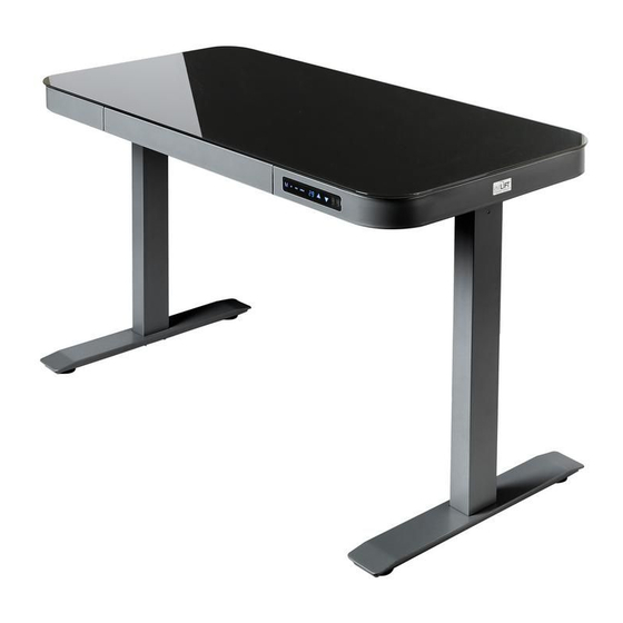
Height adjustable electric single motor desk with glass top + dual charging ports (usb-a, usb-c) + safety lock feature
Hide thumbs
Also See for airLIFT OFF65871:
- Assembly instructions manual (16 pages) ,
- Manual (16 pages)
Table of Contents
®
airLIFT
Height Adjustable Electric Single Motor Desk
with Glass Top + Dual Charging Ports (USB-A, USB-C)
+ Safety Lock Feature
Models: OFF65871 / OFF65873 / OFF65846B
Thank you for choosing Seville Classics! We hope that you enjoy your new sit-to-stand
desk. Please read through this user guide for parts list, instructions, frequently asked
questions and contact information.
V020822
Table of Contents

Related Manuals for Seville Classics airLIFT OFF65871


Summary of Contents for Seville Classics airLIFT OFF65871
- Page 1 + Safety Lock Feature Models: OFF65871 / OFF65873 / OFF65846B Thank you for choosing Seville Classics! We hope that you enjoy your new sit-to-stand desk. Please read through this user guide for parts list, instructions, frequently asked questions and contact information.
- Page 2 Congratulations on your new airLIFT® electric desk, now you can enjoy all the benefits of a truely smart and stylish workstation. We at Seville Classics® are thrilled that you’ve chosen to go airLIFT®! Our desks are some of the easiest to use, most versatile and sophisticated electronic desks on the market. With this, you can stay active throughout the day without sacrificing productivity.
-
Page 3: Table Of Contents
Table of Contents SAFETY INSTRUCTIONS ……………………………………………………………………………. COMPONENT DIAGRAM .............………………………….. PARTS LIST ........………………………………………………………………….. ASSEMBLY INSTRUCTIONS ..........……………………………. Unpack ....…………………………………………………………………………….. Install Brackets ...........………………………………………….. Install Legs ..........……………………………………………. Connect Motor ...........…………………………………………. Final Steps ......……………………………………………………………….….. INITIALIZATION & USE INSTRUCTIONS....………………………………………. 11 ADVANCED FUNCTION SETTINGS......………………………………………. 12 TROUBLESHOOTING…………………………………………………………………………………. 13 WARRANTY SERVICE INFORMATION ......………………………………. -
Page 4: Safety Instructions
Safety Instructions FAILURE TO COMPLY WITH OR OBSERVE ALL ASSEMBLY, SAFETY AND OPERATING INSTRUCTIONS AND WARNINGS REGARDING THE USE OF THIS PRODUCT MAY RESULT IN SERIOUS BODILY INJURY Read and understand this manual before attempting to install or • Assure that everyone who uses this product is informed of the contents of this manual. This •... -
Page 5: Component Diagram
Quick Setup Diagram Setup should take about 15 minutes to complete. All required tools are included. Keep the frame with tempered glass top in the box during assembly to protect it from scratches. Foot Legs/Beam Motor Power Bracket Supply Frame with LED Control Drawer Tempered Glass... -
Page 6: Parts List
Parts List A. Frame with Tempered Glass Top (Drawer, LED Control Panel, and Power Supply attached) (1) B. Legs/Beam (Motor attached) (1) C. Brackets (2) D. Feet (2) Tools & Hardware List E. M6 x 12 Screws (8) F. M8 x 16 Screws (8) G. -
Page 7: Assembly Instructions
Assembly Instructions: Unpack Remove the box lid and remove inner box containing parts. Leave the frame with tempered glass top in the TOP section of the box. Layout all components and hardware. Examine each and make sure components are without damage. Feet (x2) Pre-assembled Legs/ Beam (x1) -
Page 8: Install Brackets
Assembly Instructions: Attach Support Brackets to Legs/Beam using the M6 x 12 screws. STEP 1. Fit BRACKET (C) into the left LEG/BEAM (B) using 2 M6 x 12 SCREWS (E) for this you will need the 4 mm HEX KEY (G). Repeat this process for the right side. You should now have an assembled unit as pictured below. -
Page 9: Install Legs
Assembly Instructions: Frame with Tempered Glass Top to Legs/Beam STEP 2. Align the FRAME WITH TEMPERED GLASS TOP (A) to the FRONT, the LED Control Panel should be facing you. Center the LEGS/BEAM (B) to the frame with MOTOR SIDE TO THE LEFT, as displayed in the below figure. Motor side goes behind LED Control Panel... -
Page 10: Connect Motor
Assembly Instructions: Connect Motor Cable to LED Control Panel STEP 3. Plug in the Motor Cable from leg beam to LED Control Panel as displayed in below figure. Control Panel Motor Cable Get help with assembly and report damaged or missing parts. Email: [email protected] Telephone: 1 (800) 323-5565 Hours: 8:30 AM - 4:30 PM (PST) -
Page 11: Final Steps
Assembly Instructions: Final Steps STEP 4. Attach FEET (D) to LEGS/BEAM (B) using the M8 x 16 SCREWS (F) with the 5 mm HEX KEY (H) tool as displayed in the below figure. Tip! Take time to make sure all screws have been tightened. STEP 5. -
Page 12: Initialization & Use Instructions
Use Instructions DESK MUST BE INITIALIZED BEFORE FIRST USE Display Up Arrow Down Arrow USB Charging Port: Save Memory Memory Type A, Type C Initialize & Reset Once your desk has been put together or when reset (initialization) is necessary: 1). -
Page 13: Advanced Function Settings
Advanced Function Settings Safety Lock Lightly tap M button and the Up Arrow to lock the desk in place; press the M button and the Down Arrow to unlock. Limited Height Setting Control overall height limits of the desk to prevent the desk from going beyond a desired height level. -
Page 14: Troubleshooting
Troubleshooting Problem Action Desk does not go up or down and the Check all connections. Make sure power cord is plugged into the control box LED control panel does not illuminate and a power outlet. Press any button on the when any button is pressed. -
Page 15: Warranty Service Information
The liability of Seville Classics under the warranty shall be limited to the amount paid by the customer for the product. Seville Classics shall not be liable for any loss of use of the product, or other incidental or consequential costs, expenses or damages incurred by the customer or other user. -
Page 16: Customer Service Information
NOTE: This equipment has been tested and found to comply with the limits for Class B digital device, pursuant to part 15 of the FCC Rules. These limits are designed to provide reasonable protection against harmful interference in a residential installation. This equipment generates, uses and can radiate radio frequency energy and, if not installed and used in accordance with the instructions, may cause harmful interference to radio or television reception, which can be determined by turning the equipment off and on, the user is encouraged to try to correct the interference by one or more of the following measures:...