
Related Manuals for Honeywell PW6K1ICE


Summary of Contents for Honeywell PW6K1ICE
- Page 1 PW6K1ICE Intelligent Controller Installation and Configuration Guide 800-07985V1, Revision A September 2011 © 2011 Honeywell. All rights reserved...
- Page 2 All other product and brand names are the service marks, trademarks, registered trademarks, or registered service marks of their respective owners. Printed in the United States of America. Honeywell Integrated Security reserves the right to change any information in this document at any time without prior notice.
-
Page 3: Table Of Contents
2.15 Additional Mounting Information ..............18 Chapter 3 PW6K1ICE System Configuration via Web Interface 3.1 Overview ......................22 3.1.1 Connecting to ACDSM for the First Time ..........22 3.2 Login ........................23 3.2.1 Security Certificate.................. 24 PW6K1ICE Installation and Configuration Guide, Document 800-07985V1, Revision A... - Page 4 3.3.4 Device Info Screen .................. 30 3.3.5 Users Screen .................... 31 3.3.6 Auto Save Screen ..................32 3.3.7 Restore Default Screen ................32 3.3.8 Load Certificate Screen ................33 3.4 Initializing the System and Performing a System Download ......34 3.5 Logout ........................ 36 www.honeywell.com...
- Page 5 PW6K1ICE Introduction In this chapter... 1.1 Overview 1.3 Door Control 1.4 Access Control 1.5 Card Formats 1.7 Alarm Management 1.8 Warranty 1.9 Liability 1.10 FCC Compliance PW6K1ICE Installation and Configuration Guide, Document 800-07985V1, Revision A...
-
Page 6: Overview
The PW6K1ICE requires 12VDC for power or Power over Ethernet (PoE). The PW6K1ICE may be mounted in a 3-gang switch box; a mounting plate is supplied with the unit. Refer to “Additional Mounting Information” on page 18 for UL enclosure requirements. -
Page 7: General Ul-Compliance
• The PW6K1ICE panel must be installed within the protected area. • The PW6K1ICE is installed for indoor use only. • The PW6K1ICE must be installed with the provided tamper switch, mounted to the enclosure cover. • The fail secure locking mechanism shall only be installed where is is allowed by the local authority having jurisdiction (AHJ), and it shall not impair the operation of panic hardware and emergency egress. -
Page 8: Card Readers
PW6K1ICE Introduction Card Readers 1.6 Card Readers The Pro-Watch PW6K1ICE controller and PW6K1R1E input/output board have been tested for use with the following Listed (ALVY) card readers: Manufacturer Model Part Number ProxPro HU/5355AGN00 ProxPro II HU/5455BGN00 ProxPro K HU/5355AGK00 MiniProx... -
Page 9: Alarm Management
• Standard or custom end-of-line resistances. 1.8 Warranty Honeywell Security Access warrants that the product is free from defects in material and workmanship under normal use and service with proper maintenance for one year from the date of factory shipment. - Page 10 PW6K1ICE Introduction FCC Compliance www.honeywell.com...
- Page 11 Bulk Erase Configuration Memory Input Power Communication Wiring Reader Wiring 2.10 Input Circuit Wiring 2.11 Relay Circuit Wiring 2.12 Memory Backup Battery 2.13 Status LEDs 2.14 Specifications 2.15 Additional Mounting Information PW6K1ICE Installation and Configuration Guide, Document 800-07985V1, Revision A...
-
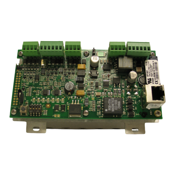
Page 12: Pw6K1Ice Hardware
.15 [3.81] 2.55 [64.77] 2.55 [64.77] .15 [3.81] .20 [5.08] TAMPER SWITCH CONNECTION (J7) ETHERNET CONNECTOR (J6) .20 [5.08] RESET SWITCH DIP SWITCHES STATUS LEDs Figure 2-2: PW6K1ICE Control Board Solder Side RELAY K2 LED RELAY K1 LED SOLDER SIDE www.honeywell.com... -
Page 13: Terminal Connections
Relay K1 - Common Contact TB5-3 Relay K1 - Normally Closed Contact TB5-4 Relay K2 - Normally Open Contact TB5-5 Relay K2 - Common Contact TB5-6 Relay K2 - Normally Closed Contact PW6K1ICE Installation and Configuration Guide, Document 800-07985V1, Revision A... -
Page 14: Jumper Configuration
Description Factory Use Only Factory Use Only (A, B, and C pads) PW6K1ICE powered from the Ethernet connection PW6K1ICE powered from an external 12VDC power source connected to TB4-3 (VIN), TB4-4 (GND) Factory Use Only Factory Use Only 10Base-T/100Base-Tx Ethernet Connection (Port 0) Cabinet Tamper: normally open switch www.honeywell.com... -
Page 15: Dip Switch Configuration
PW6K1ICE Wiring and Setup DIP Switch Configuration 2.4 DIP Switch Configuration The four switches on S1 DIP switch configure the operating mode of the PW6K1ICE processor. DIP switches are read on power-up except where noted. Pressing switch S2 causes the PW6K1ICE to reset. -
Page 16: Input Power
• The Ethernet connection using PoE, fully compliant to IEEE 802.3af, or • Local 12VDC power supply, TB4-3 (VIN), TB4-4 (GND). If the PW6K1ICE panel is powered by the local 12VDC, it must be powered by a UL 294/UL 609 Listed power supply with appropriate ratings (12VDC, 90 OmA) that is capable of providing adequate standby power. -
Page 17: Input Circuit Wiring
Custom end of line (EOL) resistances may be configured via the host software. The input circuit wiring configurations shown are supported but may not be typical: PW6K1ICE Installation and Configuration Guide, Document 800-07985V1, Revision A... -
Page 18: Relay Circuit Wiring
PW6K1ICE Wiring and Setup Relay Circuit Wiring Figure 2-5: Input Circuit Wiring Standard Supervised Circuit, 1K,1% Normally Open Contact 1K,1% 1K,1% Standard Supervised Circuit, Normally Closed Contact 1K,1% Unsupervised Circuit, Normally Closed Contact Unsupervised Circuit, Normally Open Contact 2.11 Relay Circuit Wiring Two relays are provided for controlling door lock mechanisms or alarm signaling. -
Page 19: Memory Backup Battery
If the sequence stops or repeats, perform the Bulk Erase Configuration Memory procedure described in Bulk Erase Configuration Memory, page 11. If clearing the memory does not correct the initialization problem, contact technical support. PW6K1ICE Installation and Configuration Guide, Document 800-07985V1, Revision A... -
Page 20: Specifications
(12Vdc, 900mA) and the capability to provide adequate standby power. • If the PW6K1ICE is powered by Power-Over_Ethernet (POE), it must be powered by a Listed (ALVY) Altronix, Model NetWay1 POE Injector. NetWay1 must be powered by a UL 294/UL 609 Listed power supply with appropriate ratings (24Vac/dc, 1.2A) that... - Page 21 • 500-foot (150 m) maximum Reader data • 24AWG (RS-485) • 120-ohm impedance • Twisted pair with shield • 4000-foot (1,219 m) maximum Environmental Temperature • 0 to 70°C, operating • -55 to +85°C, storage PW6K1ICE Installation and Configuration Guide, Document 800-07985V1, Revision A...
-
Page 22: Additional Mounting Information
PW6K1ICE Wiring and Setup Additional Mounting Information Humidity • 10 to 95% RHNC Mechanical Dimensions • 5.4" (140mm)W x 2.75" (70mm)L x 0.96" (24mm)H without bracket • 5.5" (140mm)W x 3.63" (92mm)L x 1.33" (34mm)H with bracket Weight • 3.8 oz. (106.35g) without bracket •... - Page 23 Additional Mounting Information Figure 2-7: Stainless Steel Blank Cover OPTIONAL BLANK COVER W/SCREWS OPTIONAL MAGNETIC TAMPER SWITCH PW6K1ICE WITH INCLUDED MOUNTING PLATE OPTIONAL 3-GANG JUNCTION BOX TO ETHERNET FIELD WIRING NETWORK PW6K1ICE Installation and Configuration Guide, Document 800-07985V1, Revision A...
- Page 24 PW6K1ICE Wiring and Setup Additional Mounting Information Figure 2-8: Mounting Plate Dimensions Ø0.16 [Ø4.0] Ø0.16 [Ø4.0] 3-GANG MGT HOLES MR50 MGT HOLES 2.35 [59.7] 3.30 [83.8] 3.63 [92.1] 3.63 [92.1] 3.85 [97.8] 5.50 [139.7] www.honeywell.com...
-
Page 25: Via Web Interface
3.3.3 Host Communication Screen 3.3.4 Device Info Screen 3.3.5 Users Screen 3.3.6 Auto Save Screen 3.3.7 Restore Default Screen 3.3.8 Load Certificate Screen Initializing the System and Performing a System Download PW6K1ICE Installation and Configuration Guide, Document 800-07985V1, Revision A... -
Page 26: Overview
PW6K1ICE System Configuration via Web Interface Overview 3.1 Overview PW6K1ICE comes with Access Control Device Server Manager (ACDSM); i.e., a built-in web server through which the users can configure their network and other system settings. The default factory-set TCP/IP address for the built-in system configuration web Note: server is 192.168.0.251... -
Page 27: Login
• If the security certificate of your server is not valid continue with the next step “Security Certificate” on page 24. • If the security certificate of your server is valid, jump to “Web Server Configuration” on page 27. PW6K1ICE Installation and Configuration Guide, Document 800-07985V1, Revision A... -
Page 28: Security Certificate
PW6K1ICE System Configuration via Web Interface Login 3.2.1 Security Certificate If there is a problem with your security certificate, the system will display the following message: Figure 3-2: Security Certificate Warning Screen If the security certificate of your server is not valid, the system will display the... - Page 29 1. To download a valid security certificate, click the About Certificate Errors link and display the certificate properties screen: Figure 3-4: Security Certificate Information Screen 2. Click Install Certificate to launch the Certificate Import Wizard: Figure 3-5: Security Certificate Import Wizard PW6K1ICE Installation and Configuration Guide, Document 800-07985V1, Revision A...
- Page 30 PW6K1ICE System Configuration via Web Interface Login 3. Click Next to display the Certificate Store screen: Figure 3-6: Certificate Store Screen 4. Select “Automatically Select the certificate store based on the type of certificate” option button and click Next to display the completion screen: Figure 3-7: Security Certificate Import Completion Screen 5.
-
Page 31: Web Server Configuration
Complete the login by entering your User Name and Password. 3.3.1 Home Screen The system will display the Home screen which has all the available configuration links on the left navigation bar: Figure 3-9: Configuration Manager Screen PW6K1ICE Installation and Configuration Guide, Document 800-07985V1, Revision A... -
Page 32: Network Settings Screen
PW6K1ICE System Configuration via Web Interface Web Server Configuration 3.3.2 Network Settings Screen 1. Click the Network link on the navigation bar to display the Network Settings screen where you can configure the IP address and hostname information: Figure 3-10: Network Settings Screen 2. -
Page 33: Host Communication Screen
Figure 3-11: Host Communication Screen 2. From the Communication Address drop-down list, select one of the eight (0 to 7) available communication addresses for the PW6K1ICE board. 3. For the Primary Host Port, make the following selections: a. Connection Type. Select IP Server. -
Page 34: Device Info Screen
PW6K1ICE System Configuration via Web Interface Web Server Configuration 4. For the Alternate Host Port, make the following selections: a. Connection Type. Select one of the following values from the drop- down list: IP Server, IP Client. b. Data Security. Select one of the following values from the drop-down list: None, Password/AES. -
Page 35: Users Screen
• Symbol characters (` ! $ ? ^ * ( ) _ - + = { [ } ] : ; @ ' ~ # | < , > . /) Example: If the password strength is set to “Medium”, the password Gertrude is valid because it has more than 6 characters and is a combination of upper and lower case. PW6K1ICE Installation and Configuration Guide, Document 800-07985V1, Revision A... -
Page 36: Auto Save Screen
PW6K1ICE System Configuration via Web Interface Web Server Configuration If the password strength is set to “High”, the password Gertrude8 is valid as long as the user name is not Gertrude. 2. Click New User to add a user. 3. Click Edit to edit an existing user. -
Page 37: Load Certificate Screen
1. Click the Load Certificate link on the navigation bar to display the Load Certificate screen: Figure 3-16: Load Certificate Screen 2. Locate the Certificate File and Private Key File by clicking the respective Browse buttons. 3. Click Load Certificate Files. PW6K1ICE Installation and Configuration Guide, Document 800-07985V1, Revision A... -
Page 38: Initializing The System And Performing A System Download
PW6K1ICE System Configuration via Web Interface Initializing the System and Performing a System Download 3.4 Initializing the System and Performing a System Download Pro-Watch software has been evaluated by UL for programming use only. Note: After creating the PW6KICE (EP1501) panel, initialize the system and perform a system download. - Page 39 After you add a PW6K1R1E downstream board to the PW6KICE, you must set the panel's MAC address and IP address (see Figure 3-18). MAC address octets must be separated by a colon. Note: PW6K1ICE Installation and Configuration Guide, Document 800-07985V1, Revision A...
-
Page 40: Logout
PW6K1ICE System Configuration via Web Interface Logout Figure 3-18: Setting MAC address and IP address 3.5 Logout Click Log Out to complete the web server configuration process and log out. www.honeywell.com... - Page 41 (This page is left blank intentionally for double-sided printing.)
- Page 42 Honeywell Integrated Security 135 W. Forest Hill Avenue Oak Creek, WI 53154 414-766-1700 414-766-1798 Fax European Office Boblingerstrasse 17 Specifications subject to change D-71101 Schonaich without notice. Germany 49-7031-637-782 © Honeywell. All rights reserved. 49-7031-637-769 Fax 800-07985V1, Revision A www.honeywell.com...