Honeywell 1000 Series Instruction Sheet
Ignition controls for combined valve and ignition system
Show thumbs
Also See for 1000 Series:
- Installation instructions manual (8 pages) ,
- Installation instructions manual (12 pages) ,
- Installation instructions manual (17 pages)
Table of Contents
IGNITION CONTROLS FOR COMBINED VALVE AND IGNITION SYSTEM
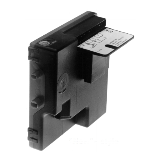
"Old"- - style
APPLICATION
The Combined Valve and Ignition system (CVI) has specially
been developed for application in gas fired appliances with
either intermittent pilot or direct burner ignition.
For this system, the VK41../VK81.. series gas controls have
been designed to have the S4565/S4575/S4585 series
ignition controls attached directly onto the valve.
The combined system then provides programmed safe light
up, flame supervision and regulation of gas flow to the main
burner and/or pilot burner of the appliance.
DESCRIPTION
The S4565/S4575 ignition controls provide automatic ignition
for direct gas burner applications and for intermittent pilot gas
burner applications with safety timer.
The S4565/S4575 ignition controls are not intended for direct
exposure to flame envelope.
The S4585 ignition controls provide automatic ignition for
intermittent pilot gas burner applications without safety timer.
The S4565/S4575/S4585 ignition controls are designed to
meet the european standards:
EN 298: Automatic gas burner control systems.
EN 60730--1: Automatic electrical controls for house hold
and similar use.
The S4565/S4575/S4585 ignition controls can be used in
appliances according European standard for household
electrical requirements EN 60335 series.
The S4565/S4575 ignition controls are approved on the North
American standard ANS Z21.20 Automatic Ignition Systems.
NOTE: S4565SD is not an ignition control but an ignition
circuit and rectifier only
S4565/S4575/S4585 SERIES
"New"- - style
. . . . . . . . . . . . . . . . . . . . . . . . . . . . . . . .
. . . . . . . . . . . . . . . . . . . . . . . . . . . . . . . . . . . . . . . . . . .
. . . . . . . . . . . . . . . . . . . . . . . . . . . . . . . . . . . . . . .
. . . . . . . . . . . . . . . . . . . . . . . . . . . . . . . . . . . . . . .
. . . . . . . . . . . . . . . . . . . . . . . . . . . . . .
. . . . . . . . . . . . . . . . . . . . . . . . . . . . . . . . . . . . . . . . . . .
. . . . . . . . . . . . . . . . . . . . . . . . . . . . .
. . . . . . . . . . . . . . . . . . . . . . . . . . . . . .
INSTRUCTION SHEET
Contents
Page
2
3
3
4
. . . . . .
7
. .
13
. . . . . . . . . . . . . . . . . .
18
23
26
27
28
EN1R--9161 0006R10--NE
Table of Contents

Related Manuals for Honeywell 1000 Series


Summary of Contents for Honeywell 1000 Series
-
Page 1: Table Of Contents
S4565/S4575/S4585 SERIES IGNITION CONTROLS FOR COMBINED VALVE AND IGNITION SYSTEM INSTRUCTION SHEET ”Old”- - style ”New”- - style APPLICATION The Combined Valve and Ignition system (CVI) has specially been developed for application in gas fired appliances with either intermittent pilot or direct burner ignition. For this system, the VK41../VK81.. -
Page 2: Dimensional Drawing
Connector pins suitable for Molex 3001 female connectors Mounting hole Ø 3.2 Ignition Flame detection Note: specific housings may deviate from drawing Fig. 1. Dimensional drawing “new style” housing in mm Connector pins suitable for Molex 3001 female connectors Mounting hole Ø 3.2 18.5 Ignition Flame detection... -
Page 3: Features
FEATURES IGNITION CONTROLS Flame supervision. Safety time triggered by Air Pressure Switch (APS) for Built--in 2.5 ... 60 Hz ignition. S4565AD ... TD “2000” series and S4575. Internal or external reset and alarm. Optional safe separation flame relay output or opto ... -
Page 4: S4565C,D,R,T
SYSTEM OPERATION NOTE 3.: If an return high limit thermostat is used, the high limit switch in the application needs a longer return time than the trial for ignition time of the control. General This in order to provide non volatile lock out. Lock- out reset Suffix A, B, P and Q (see fig. - Page 5 Ignition Length ignition cable Spark voltage: > 12 kV at 40 pF load 0.5 m max. Repetition rate: 2.5 ... 60 Hz (depending on O.S. number) Length of wiring for external components Max spark gap: 3.5 mm 1 m max. Length flame sensing cable 1 m max.
- Page 6 SYSTEM OPERATION If the flame is lost during normal run, the S4565 ignition control repeats the start sequence with prepurge. If no air is proven by the air proving switch within the prepurge General time (T ), the ignition control stays in waiting mode with fan running.
-
Page 7: S4565Ad,Bd,Cd,Dd,Pd,Qd,Rd,Td "1000" Series
Legend Thermostat Air proving switch ¯ Ignition Pilot valve Flame rod Main valve Alarm Fig. 9. Functional diagram S4565D, T SPECIFICATIONS DIRECT BURNER IGNITION CONTROL S4565AD, BD, CD, DD, PD, QD, RD, TD “1000- SERIES” Model Electrical connection Suffix AD: atmospheric, direct burner ignition High voltage spark: 2.8 x 0.5 mm spade terminal Suffix BD: as AD but with flame relay output Flame sensing: 4.8 x 0.8 mm spade terminal... - Page 8 Remark WARNING Optional integrated flame relay available with safe separation or opto coupler with safe separation. Opto coupler interface needs a debounce time > 20 N.C. contact of flame relay has no safe separation. ms in order to prevent noise caused by transients on mains.
- Page 9 Side connections ** Optional *** Optional ¯ P -- Air proving switch LM -- Limiter RS -- Reset switch See note 8. See page 10. fig. 16. *** See page 10 fig. 17. Fig. 12. Connection diagram S4565CD and DD Side connections Optional Optional ***...
- Page 10 Side connections ** Optional *** Optional ¯ P -- Air proving switch LM -- Limiter RS -- Reset switch See note 8. See page 10. fig. 16. *** See page 10 fig. 17. Fig. 15. Connection diagram S4565RD and TD Side connections Flame output...
- Page 11 SYSTEM OPERATION S4565 ignition control locks out. If the flame is lost during normal run, the S4565 ignition control repeats start sequence. General Suffix BD and QD (see fig. 19.) The S4565AD, BD, CD, DD, PD, QD, RD, TD ignition control As AD and PD except flame relay contact or opto is closed can provide both closed--loop sparking and sparking to after flame detection.
- Page 12 Legend Thermostat LPG valve Ignition Gas valve Flame rod Flame relay contact Alarm Fig. 19. Functional diagram S4565BD, QD Legend Thermostat Air proving switch Ignition Gas valve Flame rod Alarm Fig. 20. Functional diagram S4565CD, RD EN1R- -9161 0006R10- -NE...
-
Page 13: S4565Ad,Bd,Cd,Dd,Pd,Qd,Rd,Sd,Td "2000" Series
Legend Thermostat Air proving switch Ignition Gas valve Flame rod Flame relay contact Alarm Fig. 21. Functional diagram S4565DD, TD SPECIFICATIONS DIRECT BURNER IGNITION CONTROL S4565AD, BD, CD, DD, PD, QD, RD, SD, TD “2000” SERIES Model Electrical connection Suffix AD: atmospheric, direct burner ignition High voltage spark: 2.8 mm spade terminal Suffix BD: as AD but with flame relay output optional: 4 mm round terminal in spark to ground... - Page 14 Length ignition cable WARNING 0.5 m max. Length of wiring for external components Opto coupler interface needs a debounce time > 20 1 m max. ms in order to prevent noise caused by transients on mains. Remark Optional integrated flame relay available with safe separation or opto coupler with safe separation.
- Page 15 Side connections * Optional ** Optional LM -- Limiter RS -- Reset switch P -- Air pressure switch See page 16. fig. 28. See page 10 fig. 17. RS and alarm optional Fig. 24. Connection diagram S4565CD and DD “2000”series Side connections * Optional Optional **...
- Page 16 Side connections Void valves ignition used Fig. 27. Connection diagram S4565SD “2000” series Lock- out reset Side connections The S4565 can be is reset by either depressing the internal/external reset button (suffix AD, BD, CD and DD) or by interrupting the permanent life (suffix PD, QD, RD and TD). NOTE 9.: If during normal use the reset button is pressed, the gas valves close and the S4565 starts a new sequence after releasing the reset button.
- Page 17 If no air is proven by the air proving switch, the ignition control Pin 8 is present but not intended for use. It is connected with a stays waiting (optional lock out on no air can be included). resistor (100 τ) to pin 5. Ignition circuit must be on shorter than 10 s in an application Suffix DD and TD (see fig.
-
Page 18: S4565Af,Bf,Cf,Df,Ef,Pf,Qf, Rf, Tf
Legend Thermostat Air proving switch Ignition Gas valve Flame rod Alarm Fig. 32. Functional diagram S4565CD, RD “2000”series Legend Thermostat Air proving switch Ignition Gas valve Flame rod Flame relay contact Alarm Fig. 33. Functional diagram S4565DD, TD “2000”series SPECIFICATIONS IGNITION CONTROL S4565AF, BF, CF, DF, PF, QF, RF, TF Model Suffix QF: as BF except volatile lock--out Suffix RF: as CF except volatile lock--out... - Page 19 Humidity Safety time (T ): 3.5 ... 55 s Extended spark ignition time and stabilisation time: 0 ... T 90% RH max. at 40 _C (dependent on elaps of safety time) Ambient temperature External main burner interrupt 0 ... 60 _C Max open contact voltage 24 V, max current 15 mA --15 ...
- Page 20 Side connections** ¯ P -- Air proving switch Optional LM -- Limiter RS -- Reset switch See note 12. ** Alternative side connection for models with combined flame detection/high voltage. See page 5 fig. 6. Fig. 35. Connection diagram S4565CF, DF, RF, TF Side connections** CNY 17- -3 Optional...
- Page 21 NOTE 13.: If an external LPG valve and gas pressure switch no air position of the air proving switch after a self check are connected, the LPG valve is energized after period (T ) plus waiting period (T call for heat. When sufficient air flow is proven by the air proving switch, the The ignition control stays in waiting mode, until the built--in igniter and gas valve are switched on.
- Page 22 Legend Thermostat LPG outdoor valve Ignition Pilot valve Flame rod Main valve stab Alarm Fig. 38. Functional diagram S4565BF, QF Legend Thermostat Air proving switch Ignition Main valve Flame rod Alarm Fig. 39. Functional diagram S4565CF, RF EN1R- -9161 0006R10- -NE...
-
Page 23: S4575A,B,C,D,P,Q,R,T
Legend Thermostat Air proving switch Ignition Pilot valve Flame rod Main valve Main burner interrupt Alarm Fig. 40. Functional diagram S4565DF, TF SPECIFICATIONS DIRECT BURNER IGNITION CONTROL S4575A, B, P, Q Model Housing (degree of protection) Suffix A: atmospheric, direct burner ignition See page 29 Suffix B: as A but with flame relay output Timing (depending on O.S. - Page 24 Length of wiring for external components WARNING 1 m max. Remark Opto coupler interface needs a debounce Optional integrated flame relay available with safe separation time > 20 ms in order to prevent noise caused by or opto coupler with safe separation. transients on mains.
- Page 25 SYSTEM OPERATION Suffix A and P (see fig. 43.) When there is a call for heat the HSI starts glowing during glowing time (T General After the glowing time (T ) the gas valve is switched on. The S4575A, B, P, Q ignition controls can provide hot surface The igniter ignites gas and resulting flame is detected by the ignition.
-
Page 26: S4585D
SPECIFICATIONS INTERMITTENT PILOT IGNITION CONTROL S4585D Model Flame sensing Suffix D: fan assisted, intermittent pilot burner ignition Min flame current: 1.0 ←A Response time on: > 0.2 s Supply voltage Response time off (T ): < 1.0 s 220 ... 240 Vac, 50/60 Hz Phase--Phase mains trafo input: 220 ... -
Page 27: General Considerations
SYSTEM OPERATION Atmospheric ignition control S4585D (see fig. 47.) position of air proving switch after self check time (T When sufficient air flow is proven by air proving switch, a After false flame check during self check time (T ) a built--in built--in igniter and pilot gas valve are switched on. -
Page 28: Electrical Connections
ELECTRICAL CONNECTIONS AND WIRING Grommet inlet number 3 applicable for cable WARNING with Ø 4 ... Ø 7 mm. Mount the connector(s) and bring the cable grommet in Take care that installer is a trained experienced position over the cables and connector. service man. - Page 29 Housing (degree of protection) Checking flame current The minimum value should be in accordance with specified value. New style housing (see fig. 1.) To check flame current connect a DC micro--Ampèremeter Enclosure IP 20 (standard housing) between flame sensing wire and flame sensing rod. Use: strain relief set .
- Page 30 Combustion Controls Center Europe Honeywell BV Phileas Foggstraat 7, Emmen P.O. Box 83 7800 AB Emmen NL- - The Netherlands Tel: +31 (0)591 695911 Fax: +31 (0)591 695200 EN1R- -9161 0006R10- -NE...