
Related Manuals for Honeywell PCR-310


Summary of Contents for Honeywell PCR-310
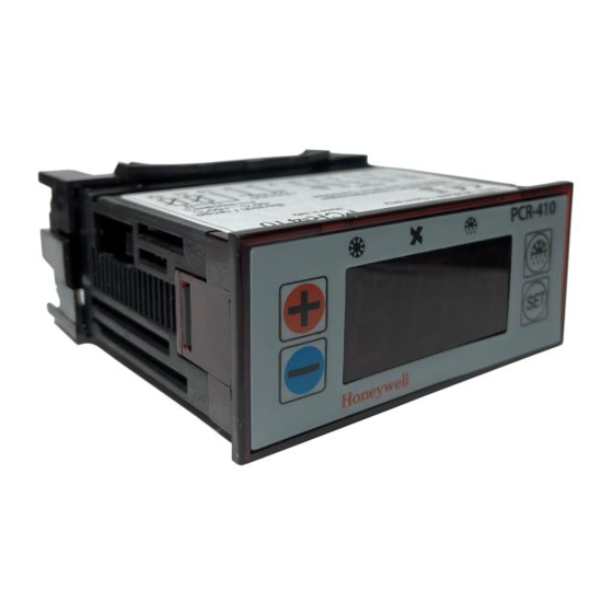
- Page 1 PCR-310 PCR-410 with TR-310 Installation and Operating Instructions Electronic refrigeration control with mains transformer...
-
Page 2: Table Of Contents
TABLE OF CONTENTS 11 Unpacking the unit and conditions of use 12 General instructions 13 Use and function 3.1 Use for the purpose intended 3.2 Function 14 Safety 4.1 Sources of danger 4.2 Safety precautions 15 Installation and commissioning 5.1 Mechanical installation 5.2 Electrical installation 5.3 Setting the dip switch for the emergency setpoint 16 Operation of the controller... -
Page 3: Unpacking The Unit And Conditions Of Use
1 Unpacking the unit and conditions of use Before and when unpacking the unit, make a visual inspection to identify any possible damage which may have occurred during transportation. Please look for loose parts, dents, scratches, etc. Report any damage immediately to the freight company. (Please see “Conditions if damage has occurred”.) In other cases, the latest edition of the “General conditions for the supply of goods and services”... -
Page 4: Function
Please take the application limits into account (see Technical Data, Chapter 12). 3.2 Function The PCR-310/-410 are microprocessor-controlled cold store controls for refrigeration and deepfreeze systems with a “snap-in” installation housing to fit in an aperture 28.5 x 70.5 mm and featuring: Compressor control (dependent upon cold store temperature) with delayed start-up. -
Page 5: Safety
4 Safety 4.1 Sources of danger Caution - Mains voltage! Never expose the unit or transformer to water or moisture. Risk of malfunction and short circuit. Only use the unit when it is adjusted to normal ambient temperature (+15 to +30 °C). Extreme changes in temperature in combination with high atmospheric humidity may lead to the formation of condensed water. -
Page 6: Installation And Commissioning
5 Installation and commissioning 5.1 Mechanical installation “Snap-in” housing: Fit the unit in an aperture 28.5 x 70.5 mm and secure it with the relevant mounting frame a) housings with terminal box cover plate (max. thickness 22 mm): b) housings without terminal box cover plate (max. -
Page 7: Electrical Installation
5.2 Electrical installation CAUTION: The mains voltage and system frequency must be the same as the nominal values on the device’s rating plate. Work on electrical systems must be performed by qualified personnel. Relevant local safety regulations must be observed. Wiring diagram;... -
Page 8: Setting The Dip Switch For The Emergency Setpoint
Controller Connection: Description: 1 – 2 = Compressor contactor (cooling) 1 – 4 (PCR-410) Alarm = Remote alarm, indicator lamp or contactor 1 – 5 = Evaporator fan (contactor) 8 – 9 12V AC/DC = Power supply 10 – 11 = Cold store sensor 10 –... -
Page 9: Operation Of The Controller
Selection of the emergency setpoint value for the cold store temperature: This will be activated if the data in the memory is lost and if alarm AL1 is activated. This sets all program parameters to the preset value. The cold store temperature setpoint can be preset to +4 °C or –18 °C, as desired. -
Page 10: Key Functions
In the event of an alarm, the most recent alarm message (e.g. AL1) and the cold store temperature are displayed alternately. Three spot indicators show the switching status of the relays during operation: Pos. 1: On : Compressor relay on. Off: Compressor relay off. -
Page 11: Adjusting The Cold Store Temperature
The input parameters are grouped together in two programming levels: Access the first programming level by pressing keys at the same time for 5 seconds. Then use the keys to access the parameters to be changed. Access the second programming level by pressing and the key simultaneously for 5 seconds. -
Page 12: Manual Defrosting
If the set temperature difference E03 is negative, an alarm is given if it is too cold in the refrigerated area, e.g. E03 = –10 K, cold store setpoint = –18 °C alarm at –28 °C in refrigerated area. If the set temperature difference E03 is positive, the alarm is given if it is too warm in the refrigerated area, e.g. - Page 13 After defrosting has been initiated manually, the next time defrosting takes place is after a complete time interval has elapsed. If the time interval between two defrost cycles is changed when the system is in operation, the new time interval will not be applied until after the next time defrosting has occurred.
-
Page 14: Sensor Calibration (Parameters E 15 And E 16)
E15 Sensor calibration T1 –5 to +5 K (cold store) E16 Sensor calibration T2 –5 to +5 K (Evaporator) E17 Operating of 0 = Relay de-energizes 2 compressor relay 1 = Relay is perma- if cold store nently energized sensor T1 is 2 = Alternately ener- defective gized/de-ener-... -
Page 15: Maintenance
8 Maintenance The controller and mains transformer do not require any maintenance. The controller does not have any fuses so, if brief voltage spikes occur, the refrigeration system will not stop operating for a prolonged period. Once the disturbance has passed, the controller will automatically start up again. -
Page 16: Problem Solving
Clearing alarm: Press the key. All alarm messages, with the exception of AL2, are also reset by switching off the operating voltage. AL2 can only be reset using key. 10 Problem solving Fault Cause Remedy Evaporator fan does Evaporator sensor T2 Refit not switch on during has fallen out... -
Page 17: Technical Data
12 Technical data Mains voltage/frequency: Controller: 12 V AC ±10%, 50/60 Hz, 12 V DC ± 10% Trans- Primary: 230 V AC ±10%, former: 50/60 Hz, Secondary: 12 V AC. Rated wattage: 2.5 watts Display: 3-digit, 7-segment, red LED, 14.2 mm Resolution: Measuring range: –55 to +50 °C... - Page 18 Sensor: 2 sensors, PTC sensors T1 = Control signal to compressor relay T2 = Control signal to defrost limitation and fan control – Sensor cable length: 2.5 m – Range where cable: –30 °C to +80 °C not fixed can be used: –40 °C to +80 °C fixed –...
- Page 19 EC Low Voltage Standard 73/23/EEC Product: FLICA, electronic coldstore control Model designation: PCR-310, PCR-410 has been developed, designed and manufactured in accordance with the EC Standards listed above. The following harmonized Standards have been applied: EN 50081-1 (1991)
- Page 20 Division of Honeywell Technologies Sàrl, Hardhofweg • 74821 Mosbach / Germany Ecublens, Route du Bois 37, Switzerland Phone: +49 (0) 62 61 / 81-475 by its autorised representative Honeywell GmbH Fax: +49 (0) 62 61 / 81-461 E-Mail: [email protected] www.honeywell-cooling.com...