Table of Contents
Quick Links
Table of Contents

Related Manuals for SAINT-GOBAIN Norton Clipper CS 451 D7


Summary of Contents for SAINT-GOBAIN Norton Clipper CS 451 D7
- Page 1 CS 451 D7 OPERATING INSTRUCTIONS Translation of the original instructions...
- Page 2 VERS.2015.07.21 CS 451 D7_MAN_EN...
-
Page 3: Cs 451 D7
Valid for machines as of serial number: 70100000 Storage site for the technical documents: Saint-Gobain Abrasives 190, Bd. J. F. Kennedy 4930 BASCHARAGE, LUXEMBOURG This declaration of conformity loses its validity when the product is converted or modified without agreement. - Page 4 VERS.2015.07.21 CS 451 D7_MAN_EN...
-
Page 5: Table Of Contents
VERS.2015.07.21 CS 451 D7_MAN_EN CS 451 D7 OPERATING INSTRUCTIONS 1 BASIC SAFETY INSTRUCTIONS 1.1 Symbols 1.2 Machine plate 1.3 Safety instructions for particular operating phases 2 GENERAL DESCRIPTION OF THE CS 451 2.1 Short description 2.2 Layout 2.3 Technical data 2.4 Statement regarding the vibration emission 2.5 Statement regarding noise emission 3 ASSEMBLY AND COMMISSIONING... -
Page 6: Basic Safety Instructions
VERS.2015.07.21 CS 451 D7_MAN_EN 1 BASIC SAFETY INSTRUCTIONS The CS 451 is exclusively designed for the cutting of floors made of asphalt, green and cured concrete (reinforced or not) as well as of industrial cement. Uses other than the manufacturer's instructions shall be considered as contravening the regulations. The manufacturer shall not be held responsible for any resulting damage. -
Page 7: Machine Plate
VERS.2015.07.21 CS 451 D7_MAN_EN Rotation of the wheel in the indicated Rotation of the wheel in the indicated direction lowers the blade direction raises the blade Never move the machine with the blade Rotation direction of the blade running idle. 1.2 Machine plate Important data can be found on the following plate located on the machine: Machine Model... -
Page 8: Safety Instructions For Particular Operating Phases
VERS.2015.07.21 CS 451 D7_MAN_EN 1.3 Safety instructions for particular operating phases Before commencing work Before commencing work, make yourself familiar with the working environment at the place of use. The working environment includes: obstacles in the area of work and manoeuvre, the firmness of the floor, necessary protection at the site relating to public thoroughfares and the availability of help in the event of accidents. -
Page 9: General Description Of The Cs 451
Any modification, which could lead to a change in the original characteristics of the machine, may be done only by Saint-Gobain Abrasives S.A. who shall confirm that the machine is still in conformity with the safety regulations. Saint-Gobain Abrasives S.A. keeps the right of making technical or design modification without prior notification. -
Page 10: Layout
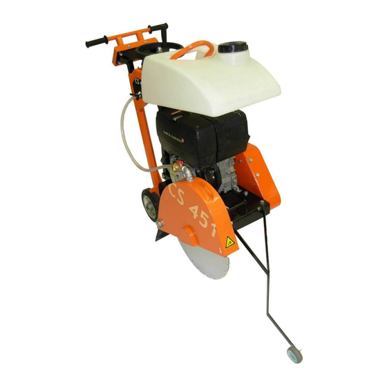
VERS.2015.07.21 CS 451 D7_MAN_EN 2.2 Layout Made of jig welded open profile steel, the CS 451 is stable but at the same time, easily transportable. The one-piece blade guard (1) fully protects the operator and his working environment. It is firmly fixed to the main frame but can be opened by rotation to change blades. - Page 11 VERS.2015.07.21 CS 451 D7_MAN_EN The precisely manufactured blade shaft is fitted into two heavy-duty self-aligning pillow block bearings, including grease nipples. On one end, a Poly-V pulley with taper lock fixing is assembled. On the other end, the shaft is reduced to 25,4mm, allowing an inner flange to be fixed. Outer flange is assembled on the shaft with a 36mm locking nut.
-
Page 12: Technical Data
VERS.2015.07.21 CS 451 D7_MAN_EN 2.3 Technical data Engine Hatz 1B30, 7HP (5kW) Fuel Diesel complying with the following minimum specifications : EN590 or DIN15601 – DK or BS 2869 A1/A2 or ASTM D975 – 1D / 2D Oil complying with the following minimum specifications: CCMC –... -
Page 13: Statement Regarding The Vibration Emission
VERS.2015.07.21 CS 451 D7_MAN_EN 2.4 Statement regarding the vibration emission Declared vibration emission value in accordance with EN 12096 Machine Measured vibration Uncertainty K Tool used Model / code emission value a m/s Model / code CS 451 D7 ZML 3270 NS Ø450x25.4 70184629089 ... -
Page 14: Statement Regarding Noise Emission
VERS.2015.07.21 CS 451 D7_MAN_EN 2.5 Statement regarding noise emission Declared value of noise emission following EN ISO 11201 and NF EN ISO 3744. Machine Sound Uncertainty K Sound power Uncertainty K Model / code Pressure level (Sound level (Sound power level Pressure level EN ISO 11201 NF EN ISO 3744... -
Page 15: Assembly And Commissioning
VERS.2015.07.21 CS 451 D7_MAN_EN 3 ASSEMBLY AND COMMISSIONING Before beginning the work with the CS 451, you have to assemble some parts. 3.1 Operator’s handle assembly Secure the operator’s handle in a comfortable user position by using the locking screws. 3.2 Tool assembly Only NORTON blades with a maximum diameter of 450 mm can be fitted on the CS 451. -
Page 16: Starting The Machine
VERS.2015.07.21 CS 451 D7_MAN_EN 3.4 Starting the machine Make sure the blade is raised clear up the ground before starting the machine. Set the speed adjuster to the STOP position, then move it to the START/RUN position, by pulling the knob and stick it on the metal part. Never use starting sprays. Pull the starting cable out by the handle until Grip the handle with both hands. -
Page 17: Transport And Storing
VERS.2015.07.21 CS 451 D7_MAN_EN 4 TRANSPORT AND STORING Take the following measures in order to transport and store the CS 451 securely. 4.1 Securing for transport Before transporting the machine: Remove the blade. Empty the water tank. Lower handles in its fixing tube and secure it using the locking screws. -
Page 18: Operating The Cs 451
VERS.2015.07.21 CS 451 D7_MAN_EN 5 OPERATING THE CS 451 5.1 Site of work Before you start working, please check the following points: Remove from the site anything, which might hinder the working procedure. Make sure the site is sufficiently well lit. ... - Page 19 VERS.2015.07.21 CS 451 D7_MAN_EN 5.2.2 Cutting the floor You can now start the engine. To make your cut, Turn the depth hand wheel until the blade slightly touches the floor. Open water valve to control the amount of water required for the type of blade, using 15 to 25l/min for wet cutting and 1-2l/min for dry cutting (dust control).
-
Page 20: Maintenance And Service
VERS.2015.07.21 CS 451 D7_MAN_EN 6 MAINTENANCE AND SERVICE CAUTION: to perform maintenance of the machine, always switch it off. Always wear a mask and safety goggles while performing the maintenance of machine. 6.1 Maintenance of the machine To ensure a long-term quality from the cutting with the CS 451, please follow the maintenance plan below: Regular service period Perform... -
Page 21: Maintenance Of The Engine
VERS.2015.07.21 CS 451 D7_MAN_EN 6.2 Maintenance of the engine Regular service period Perform operating hour interval Check level Engine oil Change Oil filter Clean Cooling air zone Check-Clean Air intake point Check-Clean Water trap Check Clean Air cleaner filter Change the cartridge Valve clearance Check and adjust... - Page 22 VERS.2015.07.21 CS 451 D7_MAN_EN Cleaning the oil filter The oil filter should be cleaned at the same time as the engine oil is changed, since oil escapes when the filter is removed. Loosen the screw « 1 » with approx. 5 Remove the oil filter from housing.
- Page 23 VERS.2015.07.21 CS 451 D7_MAN_EN Put in the oil filter and press until the limit stop. Check whether tension springs sit close to oil filter with both ends “1” before tightening. Check the oil level and restore to max. level if required. Checking the water trap The intervals at which you check the water trap depend entirely on the amount of water...
- Page 24 VERS.2015.07.21 CS 451 D7_MAN_EN Screw on the hexagonal nut « 1 » by Insert exhaust screen with hoop « 1 » into approx. 1 turn. hole, them pull outwards again so that the hoop is retained. Tighten the hexagonal nut fully.
- Page 25 VERS.2015.07.21 CS 451 D7_MAN_EN Air cleaner maintenance Remove the air cleaner cover. Unscrew and remove knurled nut “1” and take off air cleaner element “2”. Clean the filter compartment and the cover. Dirt and other foreign bodies must not be allowed to enter the engine’s air inlet points.
-
Page 26: Breakdowns: Causes And Cures
VERS.2015.07.21 CS 451 D7_MAN_EN 7 Breakdowns: causes and cures 7.1 Breakdown-finding procedures Should any breakdown occur during the use of the machine, turn it off. Let only qualified staff make any intervention other than the ones described in the previous section. 7.2 Trouble-shooting guide Trouble Possible source... -
Page 27: Customer Service
In the case of a warranty claim, the part must always be returned for evaluation. Spare parts for the engine can be ordered with the manufacturer of the engine or with their dealer, which is often quicker and cheaper. This machine has been manufactured by Saint-Gobain Abrasives S.A. 190, Bd J.F.Kennedy L- 4930 BASCHARAGE Grand-Duché... - Page 28 VERS.2015.07.21 CS 451 D7_MAN_EN Guarantee can be claimed and technical support obtained from your local distributor where machines, spare parts and consumables can be ordered as well:...
- Page 29 VERS.2015.07.21 CS 451 D7_MAN_EN...
- Page 30 VERS.2015.07.21 CS 451 D7_MAN_EN...
- Page 31 VERS.2015.07.21 CS 451 D7_MAN_EN...
- Page 32 VERS.2015.07.21 CS 451 D7_MAN_EN www.construction.norton.eu Saint-Gobain Abrasives 190, Bd. J. F. Kennedy L-4930 BASCHARAGE LUXEMBOURG Tel: ++352 50401-1 Fax: ++352 501633 e-mail: [email protected]...