ABB AC500 Installation And Configuration Manual
Hide thumbs
Also See for AC500:
- Installation instructions manual (262 pages) ,
- Introduction manual (139 pages) ,
- Safety instructions (24 pages)
Table of Contents
Quick Links
Table of Contents

Related Manuals for ABB AC500


Summary of Contents for ABB AC500
- Page 1 INSTALLATION AND CONFIGURATION MANUAL Getting started AC500 V3 products...
-
Page 2: Table Of Contents
1.3.2 System assembly, construction and connection............... 11 1.4 Example project for central I/O expansion....................12 1.4.1 Preconditions........................... 12 1.4.2 Create, set-up and save your AC500 V3 project..............12 1.4.3 Configure the I/O module......................17 1.4.4 Programming and compiling....................21 1.4.5 Set-up the communication gateway.................. -
Page 3: Getting Started With Ac500 V3 Products
Introduction > Installing Automation Builder — 1 Getting started with AC500 V3 products 1.1 Introduction This document gives an overview of the steps for the first use of a PLC with AC500 V3 CPU and describes: ● installation of the engineering software Ä... -
Page 4: Licensing Procedure
Keep the default type of installation to “Premium Edition”. Select software packages to be installed: Enable the check box “PLC - AC500 V3” to activate installation of all options for AC500 Click “Download and install” and follow the instructions of the setup. - Page 5 Start Automation Builder. ð A licensing wizard starts and guides you through the licensing procedure. Enter user information. In case of future support requests, your registration details enable ABB support team to handle your questions quickly. Select “OK”. Enable the trial license.
- Page 6 Getting started with AC500 V3 products Engineering software Automation Builder > Licensing procedure Enable the single PC license and select “Next”. Enable online activation and select “Next”. ð License activation procedure starts. A successfully ended licensing procedure ends with a success message.
-
Page 7: Set-Up Communication Parameters In Windows
Getting started with AC500 V3 products Engineering software Automation Builder > Set-up communication parameters in windows Select “OK” to end the wizard. ð Automation Builder license is activated and starts. 1.2.3 Set-up communication parameters in windows To set-up the communication between the PC and the PLC, e.g., for downloading the compiled program, you have to set-up the communication parameters. - Page 8 Getting started with AC500 V3 products Engineering software Automation Builder > Set-up communication parameters in windows Double-click Internet Protocol Version 4 (TCP/IPv4). 3ADR010584, 2, en_US 2021/05/14...
-
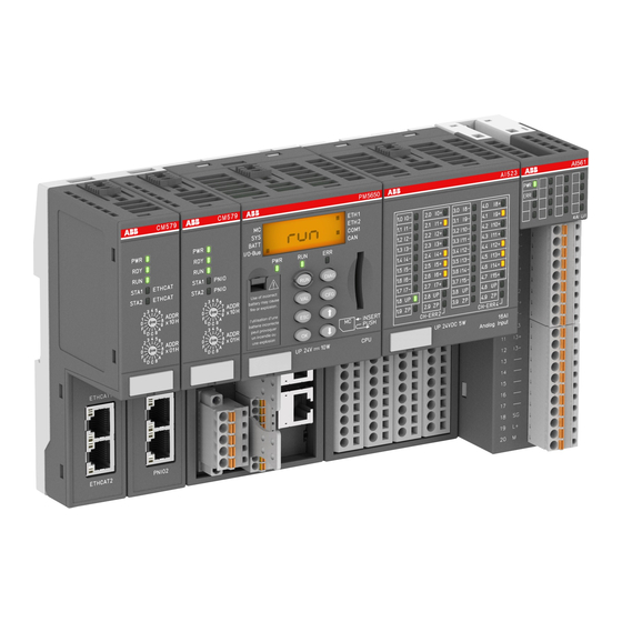
Page 9: Hardware Ac500 V3
1.3.1 Configuration for example projects The example projects require a small PLC configuration with I/O devices, e.g., as available in the training case TA5450-CASE. https://to.abb/AfO9-ftT Table 2: Modules for example projects to get started with AC500 V3 PLC Product name Type... - Page 10 Getting started with AC500 V3 products Hardware AC500 V3 > Configuration for example projects Product name Type First project Second project Ä Chapter 1.4 Ä Chapter 1.5 “Example project for “Example project for central I/O expan- remote I/O expan- sion” on page 12 sion with PROFINET”...
-
Page 11: System Assembly, Construction And Connection
– When not in use, store the equipment in appropriate static-safe packaging. You can mount AC500 PLC either to DIN rail or to a metal plate. Here, we recommend to mount on DIN rail. Snap the terminal base onto DIN rail. -
Page 12: Example Project For Central I/O Expansion
Getting started with AC500 V3 products Example project for central I/O expansion > Create, set-up and save your AC500 V3 project Plug the appropriate electronic and I/O modules in the correct locations (processor module, communication modules on terminal base, and eventually also communication interface modules and I/O modules onto dedicated terminal units). - Page 13 Getting started with AC500 V3 products Example project for central I/O expansion > Create, set-up and save your AC500 V3 project Select “Projects”. Select “AC500 project”. Fill in project name. Choose a location to save the project to. Select “OK”.
- Page 14 Getting started with AC500 V3 products Example project for central I/O expansion > Create, set-up and save your AC500 V3 project Select “Add PLC” to add the CPU to your application. 3ADR010584, 2, en_US 2021/05/14...
- Page 15 Getting started with AC500 V3 products Example project for central I/O expansion > Create, set-up and save your AC500 V3 project 1.4.2.2 Configure your CPU Double-click “PLC_AC500_V3”. ð A tab opens in the editor view. Select “CPU-Parameters Parameters”. Under parameter “Check battery”, choose the value “Off” since there is no battery present inside the CPU module.
- Page 16 Getting started with AC500 V3 products Example project for central I/O expansion > Create, set-up and save your AC500 V3 project Right-click “Application”. Select “Add Folder”. Type in "10 POUs". This is a name example. Here, the intention is to see this folder as a last one.
-
Page 17: Configure The I/O Module
Getting started with AC500 V3 products Example project for central I/O expansion > Configure the I/O module 1.4.2.4 Save the project Select menu “File è Save Project”. Alternatively, select the save icon in the tool bar. Alternatively, press [Ctrl] + [S]. - Page 18 Getting started with AC500 V3 products Example project for central I/O expansion > Configure the I/O module 1.4.3.1 Add an I/O bus module Right-click “IO_Bus” in the device tree. Select “Add object”. 3ADR010584, 2, en_US 2021/05/14...
- Page 19 Getting started with AC500 V3 products Example project for central I/O expansion > Configure the I/O module Select “S500 I/O modules”. Select “DA501” module. Select “Add object” to add the module to the I/O bus. 2021/05/14 3ADR010584, 2, en_US...
- Page 20 Getting started with AC500 V3 products Example project for central I/O expansion > Configure the I/O module 1.4.3.2 DA501 variable mapping Double-click “DA501” in the device tree. ð A tab opens in the editor view. Select “DA501 I/O Mapping” ð Here, you will map variable names (symbols) for the channels you will need in the pro- gram.