Quick Links
Power REGULATOR
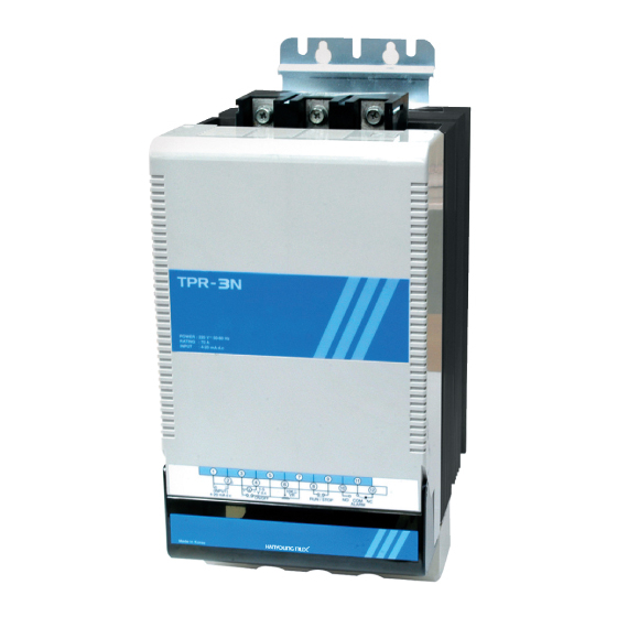
TPR-3N/TPRF-3N
INSTRUCTION MANUAL
Thank you for purchasing HANYOUNG product.
Please check whether the product is the exactly same as you ordered.
Before using the product, please read this instruction manual carefully.
Please keep this manual where you can view at any time
Safety information
Before using the product, please read the safety information thoroughly and use it properly.Alerts declared in the manual
are classified to Danger, Warning and Caution by their criticality
DANGER
DANGER indicates an imminently hazardous situation which, if not avoided, will result in death or serious injury
WARNING
WARNING indicates a potentially hazardous situation which, if not avoided, could result in death or serious injury
CAUTION
CAUTION indicates a potentially hazardous situation which, if not avoided, may result in minor or moderate injury
Danger
To prevent electric shock while it is running, put to earth with the fixed screw of the unit and do not touch
the radiator panel since it is very hot. Do not touch or contact the input/output terminals because they
cause electric shock.
Warning
• If this product is used with the machinery which may be caused human injury or serious property damage
then use it after surely installing the protection equipment for two or three times.
• To prevent defection or malfunction of this product, supply proper power voltage in accordance with the rating.
• To prevent electric shock or malfunction of product, do not supply the power until the wiring is completed.
• Do not decompose, modify, revise or repair this product. This may be a cause of malfunction, electric shock or fire.
• Reassemble this product while the power is OFF. Otherwise, it may be a cause of malfunction or electric shock
Caution
• The place of operating this product affect to the its functions and life cycle so that avoid to use it in the
following circumstance.
- A place of having high humidity and not circulating air
- A place of piling dust or impurity or having high ambient temperature or high vibration
• The contents of this manual may be changed without prior notification.
• Make sure that there is no damage or abnormality of the product during delivery.
• After turning OFF power sources of all instruments, please wire them.
• The Thyristor Power Regulator shall be installed perpendicularly.
• Install exhausting fan in internal and upside of the panel.
• Tighten BOLT of the input and output wire enough.
• Do not use this product at any place with corrosive (especially noxious gas or ammonia) or flammable gas.
• Do not use this product at any place with direct vibration or impact.
• Do not use this product at any place with liquid, oil, medical substances, dust, salt or iron contents.
(Use at Pollution level 1 or 2)
• Do not polish this product with substances such as alcohol or benzene.
• Do not use this product at any place with a large inductive difficulty or occurring static electricity or magnetic noise.
• Do not use this product at any place with possible thermal accumulation due to direct sunlight or heat radiation.
• Install this product at place under 2,000 m in altitude.
• When the product gets wet, the inspection is essential because there is danger of an electric leakage or fire.
• Do not connect anything to the unused terminals.
• After checking the polarity of terminal, connect wires at the correct position.
• The warranty period for this product including parts is one year if this product is properly used
•When installing more than 1 devices close to each other, must have gap at least 100 ㎜
Suffix code
Model
Code
TPR-3N
3 phase power regulator (no indication function)
TPRF-3N
3 phase digital Power Regulator (digital displaying type)
220
220 V a.c
Power supply
380
380 V a.c
voltage
440
440 V a.c
70
70 A
Rated Current
100
100 A
Specification
Power supply voltage
220 V a.c, 380 V a.c, 440 V a.c
Operating Frequency
50 / 60 ㎐(Dual usage)
Rated Current
70 A / 100 A
Protective circuit
Protected by the internal fuse
Normal type
Resistance load / inductive load (Select by conversion switch)
Applying
load
FND type
Resistance load / inductive load (Select by internal parameter)
Current input
4 - 20 ㎃ d.c
Voltage input
0 - 5 V d.c, 1 - 5 V d.c, 0 - 10 V d.c,
Control
input
Contact input
ON/OFF
External V.R
External volume (10 KΩ)
Normal type
Phase control, ON/OFF control (Switch selection)
Control
method
FND type
Phase control, ON/OFF control (Parameter selection)
Starting method
SOFT START / SOFT UP / DOWN
Output adjusting range
Above 95 % of input voltage (when applying max current input)
Cooling method
Forced cooling
Normal type
Indicate the output by LED
Indicating
method
FND type
Indicate the voltage and state by 7 segments
Insulation Resistance
Min. 100 ㏁ (500 V d.c Mega standard)
Output adjusting range
0 ~ 100 % (Adjust the V.R or parameter value.)
Dielectric Strength
For 1 minute at 2000 V a.c 50/60 ㎐
Line noise
Noise (2 ㎸) by the noise simulator
Ambient temperature
0 ~ 50 ℃ (but no icing allowed),
Ambient humidity
35 ~ 85 % R.H.
Storage temperature
-25 ~ 70 ℃
Weight
Approx. 5 ㎏
(70 A/100 A)
1
2
1
2
+
-
4 - 20 mA d.c
3
3
4 - 20 mA d.c
Description
HANYOUNGNUX CO.,LTD
Load side
1381-3, Juan-Dong, Nam-Gu Incheon, Korea.
HEAD OFFICE
TEL:(82-32)876-4697 FAX:(82-32)876-4696
http://www.hynux.net
PT. HANYOUNG ELECTRONIC INDONESIA
JL.CEMPAKA BLOK F 16 NO.02 DELTA SILICON II INDUSTRIAL PARK
INDONESIA
LIPPO CIKARANG CICAU, CIKARANG PUSAT BEKASI 17550 INDONESIA
FACTORY
TEL : 62-21-8911-8120~4 FAX : 62-21-8911-8126
5
1
7
Connection diagram
6
▒ Terminal arrangement
2
(Regular type / FND type)
1
2
5 6 7
Input side
+
-
4 - 20 mA d.c
External VR
10 K
11
5
7
ON/OFF control input
6
10
12
3
5
5 6 7
10 11 12
External volume
Alarm output
External VR
ALM
10 K
3
5
8
Load side
RUN/STOP
4 - 20 mA d.c
Dimension and installation panel cutout
5
9
8
5
8
9
3
11
1
5
7
2
6
10
12
RUN/STOP
3 4
1
2
5 6 7
10 11 12
+
+
-
1 - 5 V d.c
External VR
ALM
10 K
Name of each parts
3
5
9
▒ Normal type (TPR-3N)
8
3
5
8
9
RUN/STOP
External VR
10 K
•LED display
Number LED name
①
SOFT
L.ON when operates the soft start
②
O.C
L.ON when value exceeds the over current set value
③
POWER
Always L.ON when power is supplied in
④
O.T
L.ON when heat sink temperature is above 85 ℃
Generating the output more than the load break set value is generating and if load current is
⑤
L.L
less than 1A then light becomes ON
⑥
FUSE
L.ON with internal fuse break
⑦
FIRE
L.ON when output becomes ON and L.ON proportional to an output amount
⑧
AUTO
L.ON when performing auto-operation
⑨
RUN
Always L.ON when operating (RUN) (L.OFF when selecting STOP)
•Deep switch
Input signal selection
Set information SW1
4 - 20 ㎃
0 - 5 V
0 - 10 V
1 - 5 V
•Selecting the operation mode as inductive load will limit the max output to 50 %.
•Switch conversion is not recognized during operation so please supply in the power after checking the switch
3
입력신호 단
Alarm output
1
U
V
1
11
+
4 - 20 mA d.c
LOAD 부하측
▒ Input signal terminal connection diagram
10
12
(Regular type / FND type)
10 11 12
1
3
5
7
5
1
ALM
2
4
6
2
6
•when using 4 - 20 ㎃ d.c
1
2
5 6 7
입력신호 단자 결선방법
+
-
5
7
3
4 - 20 mA d.c
External VR
10 K
4
6
•when using 1 - 5 V d.c /
0 - 5 V d.c / 0 - 10 V d.c
9
3 4
5 6 7
+
-
5
11
1
7
8
1 - 5 V d.c
External VR
10 K
2
6
10
12
ON/OFF
9
3
5
1
2
5 6 7
10 11 12
+
-
외부 VR
ALM
10K
3
5
8
5
7
RUN/STOP
3
5
6
9
8
5
7
5 6 7
4
6
3
5
8
9
External VR
5 6 7
RUN/STOP
10 K
-
External VR
10 K
ON/OFF
5
7
6
5 6 7
input terminal
setting screen
displaying unit
① LED indicator
④ toggle switch
③ internal volume
and reset key
SIGNAL Terminal
load terminal
Information
Operation mode selection
SW2 Set information SW3 Set information SW1
ON
ON
Resistive load
ON
ON
OFF Inductive load OFF
OFF
ON
-
-
OFF
OFF
-
-
Load side
MB0301KE130201
11
5
7
W
2
6
10
12
2
5 6 7
10 11 12
3
5
7
-
외부 VR
ALM
4
6
10K
3 4
5 6 7
9
11
+
11
-
7
1 - 5 V d.c
External VR
8
10
12
10 K
10
12
ON/OFF
10 11 12
3
5
9
ALM
8
•when using ON/OFF
3
5
8
9
5
7
RUN/STOP
3
5
7
6
•when using external
manual volume
4
6
5 6 7
9
3 4
5 6 7
+
-
External VR
1 - 5 V d.c
외부 VR
10 K
10K
8
ON/OFF
[Unit : mm]
9
5
7
6
5 6 7
외부 VR
10K
② Deep switch
Load break selection
SW2
NON
ON
ON
30 %
OFF
ON
40 %
ON
OFF
50 %
OFF
OFF

Related Manuals for HANYOUNG NUX TPR-3N


Summary of Contents for HANYOUNG NUX TPR-3N
- Page 1 10 K ON/OFF •When installing more than 1 devices close to each other, must have gap at least 100 ㎜ Name of each parts Suffix code ▒ Normal type (TPR-3N) Model Code Description TPR-3N 3 phase power regulator (no indication function) ...
- Page 2 FND display ▒ Phase control ③ Mode displaying ① LED display 7 segment LED AC power source has 50/60 ㎐ frequency and 1/2 cycle of 60 ㎐ frequency appears a value of 0 ~180 degree in about 8.33 ㎳. Phase Control is a method that after inputting 1/2 cycle into AC power source, it proportionally generates power between 0 ~ 180 degree in 8.33 ㎳...