
Related Manuals for Fujitsu PRIMERGY RX2520 M4


Summary of Contents for Fujitsu PRIMERGY RX2520 M4
- Page 1 Operating Manual - English FUJITSU Server PRIMERGY RX2520 M4 Operating manual October 2017...
- Page 2 – The contents of this manual may be revised without prior notice. – Fujitsu assumes no liability for damages to third party copyrights or other rights arising from the use of any information in this manual. – No part of this manual may be reproduced in any without the prior written permission of Fujitsu.
- Page 3 Before reading this manual For your safety This manual contains important information for safely and correctly using this product. Carefully read the manual before using this product. Pay particular attention to the accompanying manual "Safety Notes and Regulations" and ensure these safety notes are understood before using the product.
- Page 4 Please consult the sales staff of Fujitsu if intending to use this product for high safety use. Measures against momentary voltage drop This product may be affected by a momentary voltage drop in the power supply caused by lightning.
-
Page 5: Table Of Contents
Contents Introduction ......9 Concept and target groups for this manual ..10 Documentation overview . - Page 6 Contents Starting up and operation ....63 Controls and indicators ..... 63 6.1.1 Server front .
- Page 7 Contents HDD error messages at system boot ... . . 90 Added drive reported as defective ....91 8.10 Error message on screen .
- Page 8 Contents Operating Manual RX2520 M4...
-
Page 9: Introduction
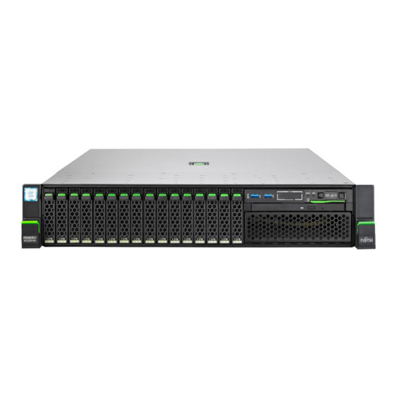
Introduction The FUJITSU Server PRIMERGY RX2520 M4 sets the standard for next- generation 2U dual-socket rack servers. With best-in-class energy efficiency, serviceability, customer-inspired design and unmatched performance, the RX2520 M4 is ideal for today’s demanding data centers. The modular design of the server offers excellent expandability with 12 memory slots, 6 PCIe Gen 3 expansion cards, and two PSUs with up to 96% efficiency. -
Page 10: Concept And Target Groups For This Manual
Documentation overview More information on your PRIMERGY RX2520 M4 can be found in the following documents: – "Quick Start Hardware - FUJITSU Server PRIMERGY RX2520 M4"... -
Page 11: Notational Conventions
Introduction – "iRMC S5 – Web Interface" user guide All documentation on PRIMERGY hardware and ServerView software is available online from the Fujitsu manuals server at: http://manuals.ts.fujitsu.com For Japan: http://www.fujitsu.com/jp/products/computing/servers/primergy/manual/ The complete PRIMERGY documentation set can also be downloaded as a DVD ISO image at: ftp://ftp.ts.fujitsu.com/images/serverview/manuals... - Page 12 Introduction Operating Manual RX2520 M4...
-
Page 13: Functional Overview
This section provides information on the features and technical data of the PRIMERGY RX2520 M4 server. For information on key characteristics and layout of the system board, see the "FUJITSU Server PRIMERGY RX2520 M4 Server Upgrade and Maintenance Manual". Features ®... - Page 14 For Japan: http://www.fujitsu.com/jp/products/computing/servers/primergy/ System board The features of the system board are described in the "FUJITSU Server PRIMERGY RX2520 M4 Upgrade and Maintenance Manual", the setup possibilities are described in the "D3386 BIOS Setup Utility for FUJITSU Server PRIMERGY RX2520 M4 Reference Manual".
- Page 15 The HDD modules are connected to the SAS/SATA backplane without cables. This allows HDD modules to be simply plugged in or pulled out (for further details see the "FUJITSU Server PRIMERGY RX2520 M4 Server Upgrade and Maintenance Manual"). If the server has a RAID configuration, the HDD modules can be exchanged during operation (hot-swap).
- Page 16 The HDD modules are connected to the SAS/SATA backplane without cables. This allows HDD modules to be simply plugged in or pulled out (for further details see the "FUJITSU Server PRIMERGY RX2520 M4 Server Upgrade and Maintenance Manual"). If the server has a RAID configuration, the HDD modules can be exchanged during operation (hot-swap).
- Page 17 Further information on other SAS/SATA RAID controllers (e.g. for operating external SAS/SATA HDDs or tape drives) is available on the Fujitsu manuals server under x86 Servers - Expansion Cards - Storage Adapters - LSI SAS / SCSI RAID Controllers. Accessible drives / components For configurations with 4 *3.5-inch and 8*3.5-inch HDD modules, a 3.5-inch...
- Page 18 Functional overview USB connectors Depending on the operation panel installed, the system has one USB 2.0 or two USB 3.0 connectors at the front, to support activities carried out by a service technician. The maximum length of the external cable is two meters for the USB connectors on the front.
- Page 19 "hides" the defective system components. The PDA (Prefailure Detection and Analysis) technology from Fujitsu analyzes and monitors all components that are critical for system reliability. A RAID controller supports different RAID levels and increase the availability and data security of the system.
- Page 20 Server management is implemented using the ServerView Operations Manager supplied and the PDA (Prefailure Detection and Analysis) technology from Fujitsu. PDA reports the threat of a system error or overload at an early stage, allowing preventive measures to be taken.
- Page 21 BIOS update. With the iRMC (integrated Remote Management Controller) on the system board, the PRIMERGY RX2520 M4 server can also be maintained and serviced remotely. This enables remote diagnosis for system analysis, remote configuration and remote restart should the operating system or hardware fail.
- Page 22 Redirection, AVR) and connect virtual drives as remote storage. More information about the iRMC S5 can be found in the "iRMC S5 – Integrated Remote Management Controller" user guide (on the Fujitsu manuals server under x86 Servers - Software - ServerView Suite - Out-Of- Band Management).
-
Page 23: Server Specification
Functional overview Server specification This section explains the specifications for the server. The specifications for this server are liable to be updated without any notice. Please be forewarned. System Board System board type D3386 ® Chipset Intel C620 series ® ®... - Page 24 Functional overview Interfaces USB connectors USB 3.0 connectors: 7 (2x front, 4x rear, 1x internal) USB connectors (12 x 3.5 inch / 24 x 2.5 inch variant) USB 2.0 connectors: 1 (1 x on front panel QRL) USB 3.0 connectors: 5 (4 x rear, 1 x internal) Graphics (15-pin) 1 x VGA (rear) Serial...
- Page 25 Functional overview Remote Management Integrated Remote Management Controller Controller (iRMC S5), 256 MB DDR3-800 SRAM for video, IPMI 2.0 compatible Trusted Platform Infineon / separate module; TCG V1.2 and TCG V2.0 Module (TPM) compliant (option) RAID controllers (expansion cards) RAID controllers Modular RAID 0/1 controller with "MegaRAID functionality"...
- Page 26 Functional overview Slots PCI-Express - Gen3 x16 3 x low profile PCI-Express - Gen3 x8 3 x low profile Slot notes CPU1 supports three slots PCIe Gen3 x8 and one slot PCIe Gen3 x16. One PCIe Gen3 x8 slot can be occupied with a Modular RAID controller.
- Page 27 Functional overview Drive bays HDD bay configuration 4x 3.5-inch, 8x3.5-inch, 12x 3.5-inch for SAS/SATA 8x 2.5-inch, 16x2.5-inch, 24x 2.5-inch for SAS/SATA Accessible drive bays 1 x 5.25/0.5-inch for ODD drive Notes accessible drives all possible options described in relevant system configurator Operating Panel Operating buttons...
- Page 28 Functional overview Dimensions / Weight Rack (W x D x H) 482.6 mm (bezel) / 444.1 mm (chassis outer dimension) / 430.8 mm (chassis) x 750 mm (outer dimension) x 86.6 mm Mounting depth rack 725.6 mm Height unit rack 19"...
- Page 29 Functional overview Noise level (depending on the configuration) The acoustic noise values are depending on the system configuration. Standard configuration Sound power level < 5.2 B (idle) (ISO 9296) < 5.3 B (operation) Sound pressure level at adjacent workstation < 34 dB(A) (idle) (ISO 9296) <...
- Page 30 Functional overview Compliance with standards Product safety and ergonomics International IEC 60950-1 2ed; am1 + am2 Europe Safety EN 60950-1 2ed; A1 + A2 + A11 + A12 EN 62479 Ergonomics ISO 9241-3 EN 29241-3 EK1-ITB2000:20xx USA / Canada CSA-C22.2 No. 60950-1-07 2ed; am1 + am2 UL 60950-1 2ed;...
- Page 31 Functional overview CAUTION! This device meets the requirements of Class A CISPR 22/32. This device can cause radio interference in residential areas. Operating Manual RX2520 M4...
- Page 32 Functional overview Operating Manual RX2520 M4...
-
Page 33: Installation Steps, Overview
Installation steps, overview This chapter contains an overview of the steps necessary to install your server. Links take you to sections where you can find more detailed information about the respective steps: Ê First of all, carefully read the safety instructions in "Important information"... - Page 34 You will find more information on installing the server remotely or locally in the "ServerView Suite Installation Manager" user’s guide (on the Fujitsu manuals server under x86 Servers - Software - ServerView Suite - Server Installation and Deployment). Operating Manual...
-
Page 35: Important Information
Important information In this chapter you will find essential information regarding safety when working on your server. Depending on your server or the installed options some information is not valid for your server. CAUTION! Before installing and starting up a server, please observe the safety instructions listed in the following section. - Page 36 Important information Before starting up During installation and before operating the server, observe the instructions ● on environmental conditions for your server. If the server is brought in from a cold environment, condensation may form ● both inside and on the outside of the server. Wait until the server has acclimatized to room temperature and is absolutely dry before starting it up.
- Page 37 Important information Always connect the server and the attached peripheral devices to the same ● power circuit. Otherwise you run the risk of losing data if, for example, the server is still running but a peripheral device (e.g. memory subsystem) fails during a power outage.
- Page 38 Important information The warranty is void if the server is damaged during installation or ● replacement of server expansions. Only set screen resolutions and refresh rates that are specified in the ● operating manual for the monitor. Otherwise, you may damage your monitor. If you are in any doubt, contact your sales outlet or customer service center.
- Page 39 Important information The battery used in this server may present a fire or chemical burn hazard if ● mistreated. Do not disassemble, heat about 100 °C (212F), or incinerate the battery. Replace the lithium battery on the system board in accordance with the ●...
- Page 40 Important information Do not pull on, press hard, or otherwise handle the CD/DVD/BD tray ● roughly. Do not disassemble the optical disk drive. ● Before use, clean the optical disk tray using a soft, dry cloth. ● As a precaution, remove disks from the optical disk drive when the ●...
- Page 41 Important information You can prevent damage from the optical disk drive and the CDs/DVDs/BDs, as well as premature wear of the disks, by observing the following suggestions: – Only insert disks in the drive when needed and remove them after use.
- Page 42 Important information The circuit boards and soldered parts of internal options are exposed and ● can be damaged by static electricity. To ensure reliable protection, you must wear an earthing band on your wrist when working with ESD modules and connect it to an unpainted, conducting metal part of the server.
- Page 43 Important information Notes on installing the server in the rack CAUTION! For safety reasons, at least 2 people are required to install the server ● in the rack because of its weight and size. (For the reader in Japan, please refer to " 安全上のご注意 ".) Never lift the server into the rack using the QRLs (Quick Release ●...
-
Page 44: Energy Star
CPU utilization levels. CE conformity :The system complies with the requirements of European Regulations. Find the CE declaration on certificate portal: https://sp.ts.fujitsu.com/sites/certificates/default.aspx To open the CE declaration applicable for your system, proceed as follows: Ê Select Industry Standard Servers. -
Page 45: Fcc Class A Compliance Statement
Consult the dealer or an experienced radio/TV technician for help. ● Fujitsu is not responsible for any radio or television interference caused by unauthorized modifications of this equipment or the substitution or attachment of connecting cables and equipment other than those specified by Fujitsu. The correction of interferences caused by such unauthorized modification, substitution or attachment will be the responsibility of the user. -
Page 46: Environmental Protection
Important information Environmental protection Environmentally-friendly product design and development This product has been designed in accordance with the Fujitsu standard for "environmentally friendly product design and development". This means that key factors such as durability, selection and labeling of materials, emissions, packaging, ease of dismantling and recycling have been taken into account. - Page 47 Further information can be found at: http://ts.fujitsu.com/recycling Details regarding the return and recycling of devices and consumables within Europe can also be found in the "Returning used devices" manual, via your local Fujitsu branch, or at: http://ts.fujitsu.com/recycling Operating Manual RX2520 M4...
- Page 48 Important information Operating Manual RX2520 M4...
-
Page 49: Hardware Installation
Hardware installation CAUTION! Follow the safety instructions in the chapter "Important information" ● on page Do not expose the server to extreme environmental conditions (see ● "Ambient conditions" on page 28). Protect the server from dust, humidity and heat. Make sure that the server is acclimatized for the time indicated in this ●... -
Page 50: Unpacking The Server
Hardware installation Unpacking the server CAUTION! Follow the safety instructions in "Important information" on page The server must always be lifted or carried by at least two people. For Japan: Please refer to " 安全上のご注意 ". Do not unpack the server until it is at its installation location. Ê... -
Page 51: Installing/Removing The Server In/From The Rack
If several units are simultaneously extended out of the rack, there is a risk that the rack could tip over. Fujitsu rack systems The rack systems from Fujitsu support the installation of PRIMERGY servers: – PRIMECENTER rack – PRIMECENTER M1 rack –... - Page 52 Hardware installation – support systems having a linear alignment feature to ensure that they can be adjusted to different rack depths Asymmetrical PRIMECENTER Rack and DataCenter Rack provide an enhanced cable management in the lateral rack area. 3rd party racks Installation in most current rack systems from other manufacturers (3rd party racks) is also supported.
-
Page 53: Connecting Devices To The Server
The connectors for external devices are on the front and rear of the server. The additional connectors available on your server depend on the expansion cards installed. For further information refer to the "FUJITSU Server PRIMERGY RX2520 M4 Server Upgrade and Maintenance Manual". - Page 54 Hardware installation Front side 3.5-inch HDD versions Figure 3: Front side 3.5-inch HDDs (up to 8 HDDs) Figure 4: Front side 3.5-inch HDDs (up to 12 HDDs) Pos. Component Front panel module Space for HDDs (depending on the configuration) Operating Manual RX2520 M4...
- Page 55 Hardware installation Front side 2.5-inch HDD versions Figure 5: Front side 2.5-inch HDDs (up to 16 HDDs or up to 8 HDDs and 4 PCIe SSDs) CAUTION The 4 PCIe SSDs can only be installed in bay 9 to 12. In this case bay 13 up to 16 have to be configured with dummy modules as shown.
- Page 56 Hardware installation Figure 7: Front side 2.5-inch HDDs (up to 24 HDDs/SSDs) Pos. Component Front panel module Space for LTO/RDX drive Space for HDDs (depending on the configuration) Operating Manual RX2520 M4...
- Page 57 Hardware installation Front side connectors 2.5-inch HDD versions Figure 8: Front side connectors 2.5-inch version Front side connectors 3.5-inch HDD versions Figure 9: Front side connectors 3.5-inch version USB 3.0 If components with large power requirements (e.g. external USB HDDs) are connected simultaneously, these USB connectors may be switched off.
- Page 58 Hardware installation Connecting the keyboard, mouse and monitor Ê Connect the keyboard and mouse to the USB connectors of the server. Ê Connect the monitor to the video connector at the rear. If a separate graphics card is installed in a slot, the graphic controller on the system board is automatically deactivated.
-
Page 59: Connecting The Server To The Mains
A second PSU can be added to ensure a redundant power supply. If one PSU is defective, the other then guarantees unimpaired operation. Each PSU can be replaced during operation (see the "FUJITSU Server PRIMERGY RX2520 M4 Server Upgrade and Maintenance Manual"). -
Page 60: Using The Cable Clamp (Ac Psu)
Hardware installation 5.4.1 Using the cable clamp (AC PSU) You can secure the power cords in a cable clamp to ensure that the insulated connectors cannot be disconnected from the server accidentally. The cable clamp is included in the accessories pack that is delivered together with the server. -
Page 61: Notes On Connecting/Disconnecting Cables
Hardware installation Notes on connecting/disconnecting cables CAUTION! Always read the documentation supplied with the device you wish to connect. Never connect, or disconnect cables during a thunderstorm. Never pull on a cable when disconnecting it. Always take hold of the cable by the plug. - Page 62 Hardware installation Information for ensuring electromagnetic compatibility All data and signal cables must have sufficient shielding. The use of cable type S/FTP Cat5 or higher is recommended. Use of unshielded or badly shielded cables may lead to increased emission of interference and/or reduced fault-tolerance of the device.
-
Page 63: Starting Up And Operation
Starting up and operation CAUTION! Follow the safety instructions in chapter "Important information" on page Controls and indicators 6.1.1 Server front 6.1.1.1 Controls on the front panel Figure 11: Controls on the front panel Figure 12: Controls on the front panel on QRL Operating Manual RX2520 M4... - Page 64 Starting up and operation Pos. Label Button Function Reboots the system. Press the reset button with a straightened end of a paper clip. RESET Reset button CAUTION! Risk of data loss! Used to troubleshoot software and device driver errors. Press the NMI button with a straightened end of a paper clip.
-
Page 65: Indicators On The Control Panel
Starting up and operation 6.1.1.2 Indicators on the control panel Figure 13: Indicators on the front panel Figure 14: Indicators on the front panel on QRL Pos. Label Indicator Status Description The server has been highlighted using ServerView Operations indicator, blue on Manager, iRMC web interface or see also... - Page 66 Starting up and operation Pos. Label Indicator Status Description No critical event detected (CSS component). orange Prefailure event detected (CSS [CSS] indicator component). orange CSS component failure detected. flashing No critical event detected (non CSS component). orange Prefailure event detected (non Global CSS component).
- Page 67 An emergency flash of the iRMC firmware is in progress. For further information on the emergency flash of the iRMC blue flashing orange flashing firmware, refer to the "FUJITSU Server PRIMERGY RX2520 M4 Upgrade and Maintenance Manual". Operating Manual RX2520 M4...
-
Page 68: Indicators On The Accessible Drives / Components
Starting up and operation 6.1.1.3 Indicators on the accessible drives / components Indicator on the ODD Figure 15: Indicator on the ODD Pos. Indicator Status Description The ODD is inactive. Activity indicator green on The storage medium is being accessed. There are also ODDs without activity indicators. - Page 69 Starting up and operation Pos. Label Indicator Status Description The HDD/SSD is inactive. Access indicator green on The HDD/SSD is being accessed. No HDD/SSD error detected. An HDD/SSD error has been detected. Possible causes: – The drive is defective and needs orange on replacing.
-
Page 70: Server Rear
Starting up and operation 6.1.2 Server rear 6.1.2.1 Indicators on the I/O panel ID, CSS, and Global Error indicators Figure 17: Global Error, ID and CSS indicators Operating Manual RX2520 M4... - Page 71 Starting up and operation Pos. Indicator Status Description The server has been highlighted using indicator, ServerView Operations Manager, iRMC web blue on see also interface or the ID button on the front panel for "iRMC- easy identification. related The server has been highlighted for easy status blue identification using the iRMC (AVR) with...
- Page 72 An emergency flash of the iRMC firmware is in progress. For further information on the orange blue flashing emergency flash of the iRMC firmware, flashing refer to the "FUJITSU Server PRIMERGY RX2520 M4 Upgrade and Maintenance Manual". Operating Manual RX2520 M4...
- Page 73 Starting up and operation LAN indicators HDD/SSD HDD/SSD HDD/SSD HDD/SSD Figure 18: Indicators on the connection panel: LAN indicators Pos. Indicator Status Description green on A LAN connection has been established. LAN is not connected. link/transfer green indicator LAN data transfer is in progress. flashing yellow on Data traffic at a transfer rate of 1 Gbit/s.
-
Page 74: Indicators On The Psu (Slide-In Unit)
Starting up and operation 6.1.2.2 Indicators on the PSU (slide-in unit) Figure 19: PSU status indicator (AC PSU) Pos. Indicator Status Description green The server is switched off, but AC voltage / flashing DC voltage is present (standby mode). The server is switched on and operating green on properly. -
Page 75: Id Card
Starting up and operation ID card You can pull out the ID card (1) as far as it will go and push it back again. The ID card contains various system information, such as the product name, serial number, order number, MAC addresses and DNS name (for Japan: only the product name and the serial number). - Page 76 Starting up and operation Figure 22: ID card - 2.5-inch variant CAUTION! There is a risk of unintentionally pushing the power button when handling the ID card. Operating Manual RX2520 M4...
-
Page 77: Switching The Server On And Off
"Safety Precautions". When operating the device outside of this operating environment, the server may operate improperly and data loss may occur. Furthermore, Fujitsu cannot be held responsible for any related damage, malfunction, or loss of data, etc. - Page 78 Starting up and operation Ê Follow the on-screen instructions (see also section "Configuring the server and installing the operating system with the ServerView Installation Manager" on page 82 or section "Configuring the server and installing the operating system without the ServerView Installation Manager"...
- Page 79 Starting up and operation – Wake up On LAN (WOL) The server is switched on by a command via the LAN (Magic Packet™). – After power failure The server automatically reboots following a power failure (depending on the settings in the BIOS or in iRMC S5). –...
-
Page 80: Configuring The Server
The controller has its own configuration utility. For further information, refer to the “Embedded MegaRAID Software User’s Guide” (on the Fujitsu manuals server under x86 Servers - Expansion Cards - Storage Adapters - LSI SAS / SCSI RAID Controllers). Descriptions of operating systems not covered in the controller manual are provided in the corresponding readme under: http://www.fujitsu.com/global/services/computing/server/ia/driver/index.html... -
Page 81: Configuring The Sas/Sata Raid Controller
A separate utility is available to the controller for MegaRAID configuration. For further information, refer to the "SAS Software User’s Guide" (on the Fujitsu manuals server under x86 Servers - Expansion Cards - Storage Adapters - LSI Configuration Software). Further information on modular RAID controllers is provided in the "Modular RAID Controller Installation Guide"... -
Page 82: Configuring The Server And Installing The Operating System With The Serverview Installation Manager
This configuration is detected automatically. Descriptions of operating systems not covered in the RAID controller manual are provided in the corresponding readme files under: http://www.fujitsu.com/global/services/computing/server/ia/driver/index.html For Japan: http://www.fujitsu.com/jp/products/computing/servers/primergy/downloads/ To find out how to operate the ServerView Installation Manager and for further information, refer to the associated manual. -
Page 83: Configuring The Server And Installing The Operating System Without The Serverview Installation Manager
Starting up and operation 6.4.4 Configuring the server and installing the operating system without the ServerView Installation Manager Configuring the onboard SATA RAID controller with "Integrated Mirroring Enhanced" Configure the controller as described in section "Configuring the onboard SATA controller" on page Configuring the SAS/SATA RAID controller (PCIe expansion card) Configure the controller as described in section "Configuring the SAS/SATA... -
Page 84: Cleaning The Server
Starting up and operation Cleaning the server CAUTION! Switch off the server and disconnect the power plugs from the properly grounded power outlets. Do not clean any interior parts yourself; leave this job to a service technician. Do not use any cleaning agents that contain abrasives or may corrode plastic. -
Page 85: Property And Data Protection
By combining these options, you can also achieve optimum protection for your system. A detailed description of the Security menu and how to assign passwords can be found in the "D3386 BIOS Setup Utility for FUJITSU Server PRIMERGY RX2520 M4 Reference Manual". Operating Manual... - Page 86 Property and data protection Operating Manual RX2520 M4...
-
Page 87: Troubleshooting And Tips
Troubleshooting and tips CAUTION! Follow the safety instructions in the "Safety notes and regulations" manual or " 安全上のご注意 " and in chapter "Important information" on page If a fault occurs, attempt to resolve it using the measures described: – in this chapter, –... -
Page 88: Server Switches Itself Off
Troubleshooting and tips Server switches itself off Server Management has detected an error Ê Check the error list of System Event Log in ServerView Operations Manager or in the iRMC web interface, and attempt to eliminate the error. Screen remains blank Monitor is switched off Ê... -
Page 89: Flickering Stripes On Monitor Screen
Troubleshooting and tips Flickering stripes on monitor screen CAUTION! Switch off the server immediately. Risk of damaging the server. Monitor does not support the set horizontal frequency Ê Find out which horizontal frequency your monitor screen supports. You will find the horizontal frequency (also known as line frequency or horizontal deflection frequency) in the documentation for your monitor. -
Page 90: Incorrect Date And Time
Further information is provided in the "Integrated RAID for SAS User’s Guide" (on the Fujitsu manuals server under x86 Servers - Expansion Cards - Storage Adapters - LSI RAID / SCSI Controllers) or in the "Modular RAID Controller Installation Guide" (on the Fujitsu manuals server under x86 Servers - Expansion Cards - Storage Adapters - LSI RAID / SCSI Controllers). -
Page 91: Added Drive Reported As Defective
If the drive continues to be shown as defective, then replace it. 8.10 Error message on screen The meaning of the error message is explained in the documentation for the relevant components and programs on the Fujitsu manuals server. 8.11 Expansion cards or onboard devices not recognized When an expansion card is added, other expansion cards or onboard devices might not be recognized. -
Page 92: Temperature Warning
The upper limit is 35°C for standard server and 40°C or 45°C with Fujitsu Advanced Thermal Design. Ê Although continued use within the temperature boundaries poses no problems within itself, reconsider the surrounding environment conditions if this log is output or if ServerView issues this notification.