Mitsubishi Electric MELSEC Q Series User Manual
Hide thumbs
Also See for MELSEC Q Series:
- User manual (834 pages) ,
- Reference manual (674 pages) ,
- Programming manual (624 pages)
Table of Contents
Quick Links
Table of Contents

Related Manuals for Mitsubishi Electric MELSEC Q Series


Summary of Contents for Mitsubishi Electric MELSEC Q Series
- Page 1 MELSEC-Q QD74MH Positioning Module User's Manual (Details) -QD74MH8 -QD74MH16...
-
Page 2: Safety Precautions
SAFETY PRECAUTIONS (Please read these instructions before using this equipment.) Before using this product, please read this manual and the relevant manuals introduced in this manual carefully and pay full attention to safety to handle the product correctly. Refer to the Users manual of the QCPU module to use for a description of the PLC system safety precautions. - Page 3 For Safe Operations 1. Prevention of electric shocks DANGER Never open the front case or terminal covers while the power is ON or the unit is running, as this may lead to electric shocks. Never run the unit with the front case or terminal cover removed. The high voltage terminal and charged sections will be exposed and may lead to electric shocks.
- Page 4 3. For injury prevention CAUTION Do not apply a voltage other than that specified in the instruction manual on any terminal. Doing so may lead to destruction or damage. Do not mistake the terminal connections, as this may lead to destruction or damage. Do not mistake the polarity ( + / - ), as this may lead to destruction or damage.
- Page 5 CAUTION The system must have a mechanical allowance so that the machine itself can stop even if the stroke limits switch is passed through at the max. speed. Use wires and cables that have a wire diameter, heat resistance and bending resistance compatible with the system.
- Page 6 CAUTION Some devices used in the program have fixed applications, so use these with the conditions specified in the instruction manual. The input devices and data registers assigned to the link will hold the data previous to when communication is terminated by an error, etc. Thus, an error correspondence interlock program specified in the instruction manual must be used.
- Page 7 CAUTION Store and use the unit in the following environmental conditions. Conditions Environment Module/Servo amplifier Servomotor Ambient 0°C to +40°C (With no freezing) According to each instruction manual. temperature (32°F to +104°F) 80% RH or less According to each instruction manual. Ambient humidity (With no dew condensation) Storage...
- Page 8 CAUTION Do not mistake the direction of the surge absorbing diode installed on the DC relay for the control signal output of brake signals, etc. Incorrect installation may lead to signals not being output when trouble occurs or the protective functions not functioning. Servo amplifier Servo amplifier 24VDC...
- Page 9 (6) Usage methods CAUTION Immediately turn OFF the power if smoke, abnormal sounds or odors are emitted from the module, servo amplifier or servomotor. Always execute a test operation before starting actual operations after the program or parameters have been changed or after maintenance and inspection. Do not attempt to disassemble and repair the units excluding a qualified technician whom our company recognized.
- Page 10 (7) Corrective actions for errors CAUTION If an error occurs in the self diagnosis of the module or servo amplifier, confirm the check details according to the instruction manual, and restore the operation. If a dangerous state is predicted in case of a power failure or product failure, use a servomotor with electromagnetic brakes or install a brake mechanism externally.
- Page 11 CAUTION After maintenance and inspections are completed, confirm that the position detection of the absolute position detector function is correct. Do not drop or impact the battery installed to the module. Doing so may damage the battery, causing battery liquid to leak in the battery. Do not use the dropped or impacted battery, but dispose of it.
-
Page 12: Revisions
This manual confers no industrial property rights or any rights of any other kind, nor does it confer any patent licenses. Mitsubishi Electric Corporation cannot be held responsible for any problems involving industrial property rights which may occur as a result of using the contents noted in this manual. -
Page 13: Table Of Contents
INTRODUCTION Thank you for choosing the high-speed, multi-axis Positioning Module QD74MH. Before using the equipment, please read this manual carefully to develop full familiarity with the functions and performance of the Positioning Module you have purchased, so as to ensure correct use. CONTENTS Safety Precautions ............................A- 1 Revisions ................................A-11... - Page 14 4.5.1 Precautions for maintenance ......................4-22 4.5.2 Disposal instructions ......................... 4-22 4.6 Daily Inspection ............................4-23 4.7 Periodic Inspection........................... 4-24 5. SPECIFICATIONS AND FUNCTIONS 5- 1 to 5- 6 5.1 Specifications of Input/Output Signals..................... 5- 1 5.1.1 List of input/output signals ........................ 5- 1 5.1.2 Input signals (QD74MH PLC CPU)....................
- Page 15 7.8.2 Setting range of OP shift amount ..................... 7-15 7.9 OP Search Limit Function........................7-16 7.9.1 Control details............................ 7-16 8. POSITIONING CONTROL 8- 1 to 8-16 8.1 Outline of Positioning Controls ........................ 8- 1 8.1.1 Data required for positioning control....................8- 1 8.1.2 Operation patterns of positioning controls..................
- Page 16 10.5.2 Data used for control........................10-12 10.6 Speed Limit Function ........................... 10-13 10.6.1 Control details..........................10-13 10.6.2 Data used for control........................10-14 10.7 Acceleration/Deceleration Control....................... 10-15 10.7.1 Control details..........................10-15 10.7.2 Data used for control........................10-16 10.8 Stop Control ............................10-17 10.8.1 Control details..........................
- Page 17 10.21.1 Control details ..........................10-40 10.22 Flash ROM Write Function ........................ 10-42 10.22.1 Control details ..........................10-42 10.22.2 Data used for control........................10-43 10.23 Parameter Initialization Function ....................... 10-44 10.23.1 Control details ..........................10-44 10.23.2 Data used for control........................10-45 10.24 Parameter Change Function ......................
-
Page 18: Using This Manual
Using This Manual The symbols used in this manual are shown below....... Symbol indicating positioning parameter item....... Symbol indicating positioning data item....... Symbol indicating monitor data item....... Symbol indicating control data item. (A serial No. is inserted in the mark.) Representation of numerical values used in this manual. - Page 19 Generic Terms and Abbreviations Unless specially noted, the following generic terms and abbreviations are used in this manual. Generic term/abbreviation Details of generic term/abbreviation PLC CPU Generic term for PLC CPU on which QD74MH can be mounted. Generic term for positioning module QD74MH8 and QD74MH16. QD74MH The module type is described to indicate a specific module.
-
Page 20: Overview
1 OVERVIEW MELSEC-Q 1. OVERVIEW This User's Manual describes the hardware specifications and handling methods of the Q series high-speed, multi-axis Positioning Module QD74MH8/QD74MH16 (herein after referred to as QD74MH). 1.1 Overview QD74MH Positioning module is used in the multiple axes without complex controls. (1) Availability of eight and sixteen axes modules (a) Eight and sixteen axes positioning modules are available. - Page 21 1 OVERVIEW MELSEC-Q (c) OPR control is given additional features (Refer to Chapter 7.) Six different OPR methods are provided: the proximity dog type, data set type, stopper type, dog cradle type, limit switch combined type, and the scale origin signal detection type. (d) Two acceleration/deceleration control methods are provided: Liner acceleration/deceleration and S-curve acceleration/deceleration.
- Page 22 1 OVERVIEW MELSEC-Q (8) Addition of forced stop function As forced stop input signal to the connector for external equipment connection is added, batch forced stop is available for all axes of servo amplifier. (Refer to Section 10.10.) Selection for "Valid/Invalid" of the forced stop input signal by external 24VDC can be made with parameter.
-
Page 23: Mechanism Of Positioning Control
1 OVERVIEW MELSEC-Q 1.2 Mechanism of Positioning Control In the positioning system using the QD74MH, software and devices are used for the following roles. The QD74MH realizes complicated positioning control when it reads in various signals, parameters and data and is controlled with the PLC CPU. Stores the created program. -
Page 24: Communicating Signals Between Qd74Mh And Each Module
1 OVERVIEW MELSEC-Q 1.3 Communicating Signals Between QD74MH and Each Module The outline of the signal communication between the QD74MH (positioning module) and PLC CPU, peripheral device and servo amplifier, etc., is shown below. PLC CPU QD74MH Servo motor PLC READY signal Position commands All axis servo ON signal Control commands... - Page 25 1 OVERVIEW MELSEC-Q (1) QD74MH ― PLC CPU The QD74MH and PLC CPU communicate the following data via the base unit. Communication Details Signal direction Signal related to commands • Y0: PLC READY signal • Y1: All axis servo ON signals Control signals •...
-
Page 26: Difference Between Qd74Mh And Qd75Mh
1 OVERVIEW MELSEC-Q 1.4 Difference Between QD74MH and QD75MH (1) Comparisons of performance specifications Model QD74MH QD75MH Item Number of control axes 8 axes/16 axes 1 axis/2 axes/4 axes Operation cycle 0.88ms 1.77ms Control unit mm, inch, degree, PLS Number of positioning data 32/axis 600/axis Linear interpolation (2, 3, 4 axes),... - Page 27 1 OVERVIEW MELSEC-Q Performance specifications (continued) Type QD74MH QD75MH Items (Note-1) Manual Incremental feed (Acceleration/deceleration: Provided) (Acceleration/deceleration: None) control Manual pulse generator input External signal input Via servo amplifier Direct input, Via servo amplifier (Upper/lower stroke limit, Near-dog) 24VDC input, Via PLC CPU, Forced stop input 24VDC input, Invalid setting enable Invalid setting enable...
- Page 28 1 OVERVIEW MELSEC-Q (2) Comparisons of input/output signals with PLC CPU specifications Model QD74MH QD75MH Item Unit READY QD75 READY Error detection Synchronization flag Warning detection Unusable Synchronization flag Axis 1 Axis 2 M code ON Axis 3 Axis 4 Axis 1 Axis 2 Unusable...
- Page 29 1 OVERVIEW MELSEC-Q Model QD74MH QD75MH Item PLC READY PLC READY All axis servo ON All axis servo ON Forced stop input Unusable Axis 1 Axis 2 Axis stop Axis 3 Axis 4 Forward run JOG start Axis 1 Unusable Reverse run JOG start Forward run JOG start Axis 2...
- Page 30 1 OVERVIEW MELSEC-Q (3) Comparisons of functions Model QD74MH QD75MH Item Communication start timing with the Control power supply ON of the PLC READY ON (First time only) servo amplifiers servo amplifier Servo ON/OFF Denominator: 32768, Denominator: 200000000, Electronic gear Numerator: 32768 Numerator: For setting units Hardware stroke limit function...
- Page 31 1 OVERVIEW MELSEC-Q (4) Comparisons of major monitor data Model QD74MH QD75MH Item Current feed value (before electronic gear) Machine feed value Feedrate (before electronic gear) Positioning data No. being executed Last executed positioning data No. OPR request OPR complete Status Positioning complete Command in-position...
-
Page 32: System Configuration
2 SYSTEM CONFIGURATION MELSEC-Q 2. SYSTEM CONFIGURATION This section describes the system configuration and configured equipments. 2.1 System Configuration Positioning module Main base unit (Q3 B) Q6 P QD74 I/O module Intelligent function module 100/200VAC Forced stop input cable USB/RS-232 (Q170DEMICBL M) Forced stop input (24VDC) Personal computer... -
Page 33: Applicable System
2 SYSTEM CONFIGURATION MELSEC-Q 2.2 Applicable System The QD74MH can be used in the following system. (1) Applicable modules and base units The table below shows the CPU modules and base units applicable to the QD74MH and quantities for each CPU module. However, the power capacity may be insufficient depending on the combination with the other installed modules and the number of installed modules. - Page 34 2 SYSTEM CONFIGURATION MELSEC-Q (b) Installing to a MELSECNET/H remote I/O station (Note-2) Usable base unit Usable network Number of installable Main base unit of Extension base unit of (Note-1) modules module remote I/O station remote I/O station QJ72LP25-25 Up to 64 QJ72LP25G QJ72BR15 : Applicable,...
-
Page 35: Component List
2 SYSTEM CONFIGURATION MELSEC-Q 2.3 Component List Product Type Remarks QD74MH8 Up to 8 axes, SSCNET compatible Positioning module QD74MH16 Up to 16 axes, SSCNET compatible GX Developer SW D5C-GPPW Refer to the GX Developer operating manual. Personal computer ― User-prepared RS-232 cable QC30R2... -
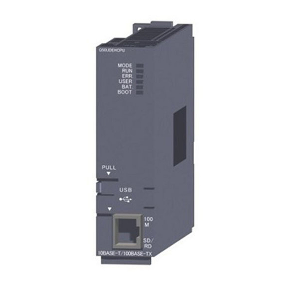
Page 36: Name Of Parts
2 SYSTEM CONFIGURATION MELSEC-Q 2.4 Name of Parts This section explains the names and LED display of the QD74MH. (1) Name of parts Side Front QD74MH16 ERR. QD74MH16 Name Application • Lit: Power supply ON 1) RUN indicator LED (green) •... - Page 37 2 SYSTEM CONFIGURATION MELSEC-Q (2) LED display The LED displays by the state of the QD74MH as follows. LED display Description Details If RUN LED (green) is OFF, RUN LED (green) is OFF. Hardware failure, exchange the unit because it ERR.
-
Page 38: Basic Specifications
2 SYSTEM CONFIGURATION MELSEC-Q 2.5 Basic Specifications (1) Module specifications Item QD74MH8 QD74MH16 Internal current consumption (5VDC) [A] 0.70 Mass [kg] 0.15 Exterior dimensions [mm(inch)] 98 (3.85)(H) × 27.4 (1.08)(W) × 90 (3.54)(D) (2) Positioning control specifications Model QD74MH8 QD74MH16 Item Number of control axes Up to 8 axes... -
Page 39: Forced Stop Input Terminal
2 SYSTEM CONFIGURATION MELSEC-Q 2.6 Forced Stop Input Terminal Item Specifications Number of input points Forced stop signal : 1 point Input method Sink/Source type Rated input current 3.5mA Isolation method Photocoupler 19.2 to 26.4VDC Operating voltage range (+10/ -20%, ripple ratio 5% or less) ON voltage/current 17.5VDC or more/3.0mA or more OFF voltage/current... -
Page 40: Checking Function Version And Serial No
Serial number (First 6 digits) Function version S ER I A L 100511100511999- B 80M1 IND. CONT. EQ US LISTED MITSUBISHI ELECTRIC MA D E IN JA PA N QD74MH8 100511100511999- B Function version Serial number (First 6 digits) 2 - 9... - Page 41 2 SYSTEM CONFIGURATION MELSEC-Q (2) Checking function version on the system monitor screen (Module’s Detailed Information) Select [Module’s Detailed Information] button on the system monitor screen (Note-1) displayed on [Diagnostics] – [System monitor] of GX Developer The function version can be checked in [Product Information] displayed on the Module’s Detailed Information screen.
-
Page 42: Design
3 DESIGN MELSEC-Q 3. DESIGN 3.1 System Designing Procedure Design the system which uses the QD74MH in the following procedure. Positioning control system design Select the QD74MH according to number of control axes. Select I/O modules according to the specifications of the external Refer to MELSEC-Q equipment to be controlled. -
Page 43: External Circuit Design
3 DESIGN MELSEC-Q 3.2 External Circuit Design Configure up the power supply circuit and main circuit which turn off the power supply after detection alarm occurrence and servo forced stop. When designing the main circuit of the power supply, make sure to use a no fuse breaker (NFB). The outline diagrams of the internal circuits for the external device connection interface are shown below. - Page 44 3 DESIGN MELSEC-Q POINT (1) (Note-1): Configure up the power supply circuit which switch off the electromagnetic contactor (MC) after detection alarm occurrence on the PLC CPU. (2) (Note-2): It is also possible to use a full wave rectified power supply as the power supply for the electromagnetic brake. (3) (Note-3): It is also possible to use forced stop signal of the servo amplifier.
- Page 45 3 DESIGN MELSEC-Q (2) Example when using the forced stop of the QD74MH and MR-J3-B 3-phase 200 to 230VAC Power Supply PLC CPU Positioning Output module module Q61P QnCPU QY41P NFB1 QD74MH R S T INPUT 100-240VAC 12/24VDC Forced stop (Note-5) EMI.COM SSCNET...
- Page 46 3 DESIGN MELSEC-Q POINT (1) (Note-1): Configure up the power supply circuit which switch off the electromagnetic contactor (MC) after detection alarm occurrence on the PLC CPU. (2) (Note-2): It is also possible to use a full wave rectified power supply as the power supply for the electromagnetic brake. (3) (Note-3): Set the servo amplifier by setting the rotary switch of servo amplifier referring Section 4.2.1.
-
Page 47: Power Supply Circuit Design
3 DESIGN MELSEC-Q 3.2.1 Power supply circuit design This section describes the protective coordination and noise suppression techniques of the power supply circuit. (1) Separation and protective coordination (leakage current protection, over current protection) of power supply lines Separate the lines for PLC system power supplies from the lines for I/O devices and servo amplifiers as shown below. -
Page 48: Safety Circuit Design
3 DESIGN MELSEC-Q 3.2.2 Safety circuit design (1) Concept of safety circuits When the PLC system is powered on and off, normal control output may not be done momentarily due to a delay or a startup time difference between the PLC power supply and the external power supply (DC in particular) for the control target. - Page 49 3 DESIGN MELSEC-Q (b) The forced stop of all servo amplifiers is possible in a lump by using the forced stop input signal [Y2] of QD74MH. After forced stop, the forced stop factor is removed and the forced stop canceled. (The servo error detection signal does not turn on with the forced stop.) The wiring example and program example that uses the forced stop input of input module (QX10) is shown below.
-
Page 50: Installation, Wiring, Start-Up And Maintenance
4 INSTALLATION, WIRING, START-UP AND MAINTENANCE MELSEC-Q 4. INSTALLATION, WIRING, START-UP AND MAINTENANCE This section describes the installation, wiring, start-up and maintenance of the product. 4.1 Handling Precautions (1) Main body • The main body case is made of plastic. Take care not to drop or apply strong impacts onto the case. - Page 51 4 INSTALLATION, WIRING, START-UP, AND MAINTENANCE MELSEC-Q DANGER Completely turn off the externally supplied power used in the system before clearing or tightening the screws. Not doing so could result in electric shock. CAUTION Use the programmable controller in an environment that meets the general specifications contained in CPU module User's Manual to use.
-
Page 52: Wiring
4 INSTALLATION, WIRING, START-UP, AND MAINTENANCE MELSEC-Q 4.2 Wiring The precautions for wiring are given below. DANGER Completely turn off the externally supplied power used in the system before installation or wiring. Not doing so could result in electric shock or damage to the product. CAUTION Check the layout of the terminals and then properly route the wires to the module. -
Page 53: Sscnet Cable
4 INSTALLATION, WIRING, START-UP, AND MAINTENANCE MELSEC-Q 4.2.1 SSCNET cable (1) Precautions of SSCNET cable wiring SSCNET cable is made from optical fiber. If optical fiber is added a power such as a major shock, lateral pressure, haul, sudden bending or twist, its inside distorts or breaks, and optical transmission will not be available. - Page 54 4 INSTALLATION, WIRING, START-UP, AND MAINTENANCE MELSEC-Q (d) Twisting If the SSCNET cable is twisted, it will become the same stress added condition as when local lateral pressure or bend is added. Consequently, transmission loss increases, and the breakage of SSCNET cable may occur at worst.
- Page 55 4 INSTALLATION, WIRING, START-UP, AND MAINTENANCE MELSEC-Q • Bundle fixing Optical cord should be given loose slack to avoid from becoming smaller than the minimum bend radius, and it should not be twisted. When laying cable, fix and hold it in position with using cushioning such as sponge or rubber which does not contain plasticizing material.
- Page 56 4 INSTALLATION, WIRING, START-UP, AND MAINTENANCE MELSEC-Q (2) Connection of SSCNET cables The connection method of SSCNET cable between QD74MH and servo amplifier is explained as follows. When absolute position detection control is executed, installed battery (MR-J3BAT) to servo amplifier. QD74MH SSCNET cable length MR-J3BUS M use...
- Page 57 4 INSTALLATION, WIRING, START-UP, AND MAINTENANCE MELSEC-Q (3) Setting of the axis number and axis select rotary switch of servo amplifier Axis number is used to set the axis numbers of servo amplifiers connected to SSCNET connector(CN1) in the program. Axis number of 1 to 16 can be set for QD74MH16, and axis number of 1 to 8 can be set for QD74MH8.
- Page 58 4 INSTALLATION, WIRING, START-UP, AND MAINTENANCE MELSEC-Q (4) Precautions for handling the SSCNET cable • Do not stamp the SSCNET cable. • When laying the SSCNET cable, be sure to secure the minimum cable bend radius or more. If the bend radius is less than the minimum cable bend radius, it may cause malfunctions due to characteristic deterioration, wire breakage, etc.
- Page 59 4 INSTALLATION, WIRING, START-UP, AND MAINTENANCE MELSEC-Q CAUTION Be sure to use the SSCNET cable within the range of operating temperature described in this manual. Especially, as optical fiber for MR-J3BUS M and MR-J3BUS M-A are made of synthetic resin, it melts down if being left near the fire or high temperature. Therefore, do not make it touched the part which becomes high temperature, such as radiator or regenerative option of servo amplifier, or servomotor.
- Page 60 4 INSTALLATION, WIRING, START-UP, AND MAINTENANCE MELSEC-Q CAUTION When exchanging the QD74MH or servo amplifier, make sure to put cap on SSCNET connector. When asking repair of QD74MH or servo amplifier for some troubles, make also sure to put a cap on SSCNET connector.
- Page 61 4 INSTALLATION, WIRING, START-UP, AND MAINTENANCE MELSEC-Q CAUTION Use the processing method and the processing treatment device that exists in the connector when you fix the cord part of the SSCNET cable to the connector. It must not cut squarely when you cut the cord part of the SSCNET cable, the cutting edge side must not be made smooth, and garbage etc.
- Page 62 4 INSTALLATION, WIRING, START-UP, AND MAINTENANCE MELSEC-Q b) Exterior dimensions • MR-J3BUS015M [Unit: mm(inch)] 13.4 37.65 6.7(0.26) (0.59) (0.53) (1.48) Protective tube (5.91) • MR-J3BUS03M to MR-J3BUS3M Refer to the table of this section (5) for cable length (L). [Unit: mm(inch)] Protective tube (Note) (3.94)
- Page 63 4 INSTALLATION, WIRING, START-UP, AND MAINTENANCE MELSEC-Q 2) SSCNET cable connector [Unit: mm(inch)] 4.8(0.19) (0.07) (0.09) 17.6 0.2 (0.69 0.01) (0.31) 20.9 0.2 (0.82 0.01) 4 - 14...
-
Page 64: Forced Stop Input Cable
4 INSTALLATION, WIRING, START-UP, AND MAINTENANCE MELSEC-Q 4.2.2 Forced stop input cable (1) Precautions for handling the forced stop input cable For connection or removal of the forced stop input cable, do it surely while holding a connector of forced stop input cable. QD74MH (2) Connection of the forced stop input cable For connection of a forced stop input cable to the QD74MH, connect it surely to... - Page 65 4 INSTALLATION, WIRING, START-UP, AND MAINTENANCE MELSEC-Q (4) Specifications of forced stop input cable Generally use the forced stop input cable available as our products. If the required length is not found in our products, fabricate the cable on the customer side.
-
Page 66: Confirming The Installation And Wiring
4 INSTALLATION, WIRING, START-UP, AND MAINTENANCE MELSEC-Q 4.3 Confirming the Installation and Wiring 4.3.1 Items to confirm when installation and wiring are completed Confirm the wiring after installation and wiring. Confirm the following points in the buffer memory using GX Developer. •... -
Page 67: Start-Up
4 INSTALLATION, WIRING, START-UP, AND MAINTENANCE MELSEC-Q 4.4 Start-up 4.4.1 Checklist before trial operation Table 4.3 Checklists before trial operation Model name Confirmation Items Check Reference (1) Check that the main base unit has been suited with the CPU module to be used. -
Page 68: Trial Operation And Adjustment Procedure
4 INSTALLATION, WIRING, START-UP, AND MAINTENANCE MELSEC-Q 4.4.2 Trial operation and adjustment procedure Servo start-up procedure Turn OFF PLC system power supply Check that the system power supply is OFF. Check wiring and module installation Refer to the QCPU User's Manual (Hardware Design, Maintenance and Inspection) for installation of module. - Page 69 4 INSTALLATION, WIRING, START-UP, AND MAINTENANCE MELSEC-Q CAUTION Create PLC programs Create the PLC programs using Set parameter values to those that are compatible GX Developer. with the controller, servo amplifier, servomotor Set the following positioning parameters. and regenerative resistor model name and the (1) Basic parameters system name application.
- Page 70 4 INSTALLATION, WIRING, START-UP, AND MAINTENANCE MELSEC-Q CAUTION Check machine operation Check the followings by making the The system must have a mechanical allowance so machine operate with the JOG operation. that the machine itself can stop even if the stroke (1) Machine operates correctly limits switch is passed through at the max.
-
Page 71: Maintenance
4 INSTALLATION, WIRING, START-UP, AND MAINTENANCE MELSEC-Q 4.5 Maintenance 4.5.1 Precautions for maintenance The precautions for servicing are given below. Refer to this section as well as "4.1 Handling Precautions" when carrying out the work. DANGER Completely turn off the externally supplied power used in the system before clearing or tightening the screws. -
Page 72: Daily Inspection
4 INSTALLATION, WIRING, START-UP, AND MAINTENANCE MELSEC-Q 4.6 Daily Inspection The items that must be inspected daily are shown below. Table 4.4 Daily inspection Item Inspection item Inspection Criterion Action Check that the fixing screws are not loose Retighten the Mounting of base unit The screws and cover must be mounted securely. -
Page 73: Periodic Inspection
4 INSTALLATION, WIRING, START-UP, AND MAINTENANCE MELSEC-Q 4.7 Periodic Inspection The items that must be inspected one or two times every 6 months to 1 year are listed below. When the equipment is moved or modified, or layout of the wiring is changed, also implement this inspection. -
Page 74: Specifications And Functions
5 SPECIFICATIONS AND FUNCTIONS MELSEC-Q 5. SPECIFICATIONS AND FUNCTIONS This section describes the input/output signals with PLC CPU and functions. 5.1 Specifications of Input/Output Signals 5.1.1 List of input/output signals The QD74MH uses 32 input points and 32 output points for exchanging data with the PLC CPU. - Page 75 5 SPECIFICATIONS AND FUNCTIONS MELSEC-Q 5.1.2 Input signals (QD74MH PLC CPU) Device No. Signal name Details • When the PLC READY signal [Y0] turns from OFF to ON, the parameter setting range is checked. If no error is found, this signal turns ON. •...
-
Page 76: Qd74Mh)
5 SPECIFICATIONS AND FUNCTIONS MELSEC-Q 5.1.3 Output signals (PLC CPU QD74MH) Device No. Signal name Details (a) This signal notifies the QD74MH that the PLC CPU is normal. • It is turned ON/OFF with the sequence program. (b) This signal turns OFF at the change of the basic parameters or OPR parameters. -
Page 77: Functions
5 SPECIFICATIONS AND FUNCTIONS MELSEC-Q 5.2 Functions 5.2.1 QD74MH control functions (1) OPR control "OPR control" is a function that established the start point for carrying out positioning control, and carries out positioning toward that start point. This is used to return a workpiece, located at a position other than the OP when the power is turned ON or after positioning stop, to the OP. -
Page 78: Functions Of Qd74Mh
5 SPECIFICATIONS AND FUNCTIONS MELSEC-Q 5.2.2 Functions of QD74MH Functions of QD74MH are shown below. Reference Functions Details section • Proximity dog type • Data set type • Stopper type This function mechanically establishes the positioning start point using a Chapter 7 •... - Page 79 5 SPECIFICATIONS AND FUNCTIONS MELSEC-Q Reference Functions Details section Target position change function This function changes the target position during positioning operation. 10.16 Current value change function This function changes the feed current value to any address. 10.17 External signal logic selection This function selects a logic of I/O signals.
-
Page 80: Data Used For Positioning Control
6 DATA USED FOR POSITIONING CONTROL MELSEC-Q 6. DATA USED FOR POSITIONING CONTROL 6.1 Memory Configuration and Roles The QD74MH is equipped with the following two memories for data exchange with PLC CPU and data save. Table 6.1 Memory configuration Area configuration Memory Role... - Page 81 6 DATA USED FOR POSITIONING CONTROL MELSEC-Q (2) Reading/writing data from buffer memory Read and write the data from the buffer memory in the following method. (a) Reading 1) Sequence program • 1 word ..Use FROM instruction or intelligent function device. •...
-
Page 82: Data Transmission Process
6 DATA USED FOR POSITIONING CONTROL MELSEC-Q 6.2 Data Transmission Process 6.2.1 Data transmission process for operation PLC CPU TO(P) instruction, DTO(P) instruction FROM(P) instruction, DFRO(P) instruction MOV(P) instruction, DMOV(P) instruction MOV(P) instruction, DMOV(P) instruction QD74MH Internal memory Buffer memory Flash ROM System power supply ON/ PLC READY ON... - Page 83 6 DATA USED FOR POSITIONING CONTROL MELSEC-Q (3) PLC READY ON (a) The buffer memory data of QD74MH can be taken to the internal memory. (Refer to Section 6.4 for the parameters taken at the PLC READY ON.) (b) The communication starts with servo amplifiers at the PLC READY ON (first time only) after the system power supply ON, and the servo parameters to the buffer memory can be transmitted from QD74MH to the servo amplifier.
-
Page 84: Setting Of Servo Amplifier Series
6 DATA USED FOR POSITIONING CONTROL MELSEC-Q 6.2.2 Setting of servo amplifier series Up to 8 axes servo amplifies in QD74MH8 and up to 16 axes servo amplifies in QD74MH16 can be connected. Set the servo amplifier series in the servo parameter for each axis. -
Page 85: Exchange Of The Servo Parameters
6 DATA USED FOR POSITIONING CONTROL MELSEC-Q 6.2.3 Exchange of the servo parameters This section describes the exchange of the servo parameters. (1) Writing the servo parameters from QD74MH to servo amplifier Some servo parameters become valid by turning OFF/ON of the power supply of the servo amplifiers. - Page 86 6 DATA USED FOR POSITIONING CONTROL MELSEC-Q (2) Transmitting the servo parameters from servo amplifier to buffer memory of QD74MH The parameters changed in the servo amplifier can be automatically transmitted to the buffer memory of QD74MH. However, they cannot be transmitted to the flash ROM of QD74MH.
-
Page 87: Buffer Memory Configuration
6 DATA USED FOR POSITIONING CONTROL MELSEC-Q 6.3 Buffer Memory Configuration This section describes the configuration and contents of the buffer memory. Table 6.3 List of buffer memory Buffer memory address Buffer memory area configuration Axis 1 Axis 2 Axis 15 Axis 16 Basic parameter 0 to 49... - Page 88 6 DATA USED FOR POSITIONING CONTROL MELSEC-Q (1) List of basic parameter Axis No. Buffer memory address Parameter item 0 to 49 100 to 149 Symbol Parameter item 200 to 249 Pr.0 Electronic gear numerator (AP) 300 to 349 400 to 449 Pr.2 Electronic gear denominator (AL) 500 to 549...
- Page 89 6 DATA USED FOR POSITIONING CONTROL MELSEC-Q (2) List of OPR parameter Axis No. Buffer memory address Parameter item 50 to 79 150 to 179 Symbol Parameter item 250 to 279 Pr.50 OPR method 350 to 379 Pr.51 OPR direction 450 to 479 Pr.52 OP address...
- Page 90 6 DATA USED FOR POSITIONING CONTROL MELSEC-Q (3) List of manual control parameter Axis No. Buffer memory address Parameter item 80 to 99 180 to 199 Symbol Parameter item 280 to 299 Pr.80 JOG speed 380 to 399 480 to 499 Pr.82 JOG operation acceleration time 580 to 599...
- Page 91 6 DATA USED FOR POSITIONING CONTROL MELSEC-Q (4) List of system parameter Buffer memory address Symbol Parameter item Buffer memory address Symbol Parameter item 1600 — Unusable 1650 1601 Pr.101 External forced stop selection 1651 1602 1652 1603 1653 1604 1654 1605 1655...
- Page 92 6 DATA USED FOR POSITIONING CONTROL MELSEC-Q (5) List of axis monitor data Buffer memory Axis No. Parameter item address 1700 to 1799 1800 to 1899 Symbol Parameter item Symbol Parameter item 1900 to 1999 Md.0 Current feed value 2000 to 2099 2100 to 2199 Md.2 Feedrate...
- Page 93 6 DATA USED FOR POSITIONING CONTROL MELSEC-Q (6) List of system monitor data Buffer memory address Symbol Parameter item Buffer memory address Symbol Parameter item 3300 Md.100 Axis error status 3350 3301 Md.101 Axis warning status 3351 Number of write accesses to 3352 3302 Md.102...
- Page 94 6 DATA USED FOR POSITIONING CONTROL MELSEC-Q (7) List of axis control data Buffer memory Axis No. Parameter item address 3400 to 3499 3500 to 3599 Symbol Parameter item Symbol Parameter item 3600 to 3699 Cd.0 Axis error reset 3700 to 3799 Cd.1 Parameter change request 3800 to 3899...
- Page 95 6 DATA USED FOR POSITIONING CONTROL MELSEC-Q (8) List of system control data Buffer memory address Symbol Parameter item Buffer memory address Symbol Parameter item 5000 Cd.100 Flash ROM write request 5050 5001 Cd.101 Parameter initialization request 5051 5002 5052 5003 5053 5004...
- Page 96 6 DATA USED FOR POSITIONING CONTROL MELSEC-Q (9) List of positioning data Axis Point Buffer memory Axis Point Buffer memory Parameter item Parameter item address address 5100 to 5109 5740 to 5749 5110 to 5119 Symbol Parameter item 5750 to 5759 Symbol Parameter item 5120 to 5129...
- Page 97 6 DATA USED FOR POSITIONING CONTROL MELSEC-Q List of positioning data (Continued) Axis Point Buffer memory Axis Point Buffer memory Parameter item Parameter item address address 6380 to 6389 7020 to 7029 6390 to 6399 Symbol Parameter item 7030 to 7039 Symbol Parameter item 6400 to 6409...
- Page 98 6 DATA USED FOR POSITIONING CONTROL MELSEC-Q List of positioning data (Continued) Axis Point Buffer memory Axis Point Buffer memory Parameter item Parameter item address address 7660 to 7669 8300 to 8309 7670 to 7679 Symbol Parameter item 8310 to 8319 Symbol Parameter item 7680 to 7689...
- Page 99 6 DATA USED FOR POSITIONING CONTROL MELSEC-Q List of positioning data (Continued) Axis Point Buffer memory Axis Point Buffer memory Parameter item Parameter item address address 8940 to 8949 9580 to 9589 8950 to 8959 Symbol Parameter item 9590 to 9599 Symbol Parameter item 8960 to 8969...
- Page 100 6 DATA USED FOR POSITIONING CONTROL MELSEC-Q (9) List of servo parameter Axis Buffer memory Parameter item address 10300 to 10599 10600 to 10899 Symbol Parameter item Symbol Parameter item 10900 to 11199 Pr.300 — Servo series Pr.345 PB13 Machine resonance suppression filter 1 11200 to 11499 Pr.301 PA01 For manufacturer setting Pr.346 PB14 Notch shape selection 1...
- Page 101 6 DATA USED FOR POSITIONING CONTROL MELSEC-Q List of servo parameter (Continued) Axis Buffer memory Parameter item address 10300 to 10599 10600 to 10899 Symbol Parameter item Symbol Parameter item 10900 to 11199 Pr.390 PC10 Analog monitor 2 output 143 Pr.443 PD31 11200 to 11499 Pr.391 PC11 Analog monitor 1 offset 144 Pr.444 PD32...
- Page 102 6 DATA USED FOR POSITIONING CONTROL MELSEC-Q List of servo parameter (Continued) Axis Buffer memory Parameter item address 10300 to 10599 10600 to 10899 Symbol Parameter item Symbol Parameter item 10900 to 11199 196 Pr.496 PS04 248 Pr.548 11200 to 11499 197 Pr.497 PS05 249 Pr.549 11500 to 11799...
-
Page 103: Parameter Data
6 DATA USED FOR POSITIONING CONTROL MELSEC-Q 6.4 Parameter Data The setting value of parameters (basic, OPR, system) is checked at the PLC READY ON. (The manual control parameters cannot be checked.) If the setting value is outside the range, the error code will occur and the unit READY cannot be turned ON. - Page 104 6 DATA USED FOR POSITIONING CONTROL MELSEC-Q Buffer Factory memory Symbol Items Details Setting range Fetch timing Unit default address Set the group to specify the 0: None combination for axes to be interpolation-controlled. (Single axis) Set the same group number for 1: Group 1 Pr.25 25+100n Interpolation group...
-
Page 105: Opr Parameter
6 DATA USED FOR POSITIONING CONTROL MELSEC-Q 6.4.2 OPR parameter (1) OPR parameter Buffer Factory memory Symbol Items Details Setting range Fetch timing Unit default address 0: Proximity dog 2: Data set 3: Stopper 4: Dog cradle Pr.50 50+100n OPR method Select the OPR method. -
Page 106: Manual Control Parameter
6 DATA USED FOR POSITIONING CONTROL MELSEC-Q (2) OPR parameter (MR-J3- B-RJ004 use) Buffer Factory memory Symbol Items Details Setting range Fetch timing Unit default address Set whether the incremental linear scale is used for OPR (except scale origin signal 1: Used detection type). -
Page 107: Monitor Data
6 DATA USED FOR POSITIONING CONTROL MELSEC-Q 6.5 Monitor Data 6.5.1 Axis monitor data (1) Axis monitor data Buffer Symbol memory Items Details Updated cycle Unit address The currently commanded address can be stored. When the current value is changed with the current value 1700+100n Md.0 Current feed value... - Page 108 6 DATA USED FOR POSITIONING CONTROL MELSEC-Q Buffer memory Symbol Items Details Updated cycle Unit address The ON/OFF state of various signals can be stored. Md.9 1709+100n Status 1 — b0: OPR request b1: OPR complete The ON/OFF state of various signals can be stored. Status change b0: Positioning complete b1: Command in-position...
- Page 109 6 DATA USED FOR POSITIONING CONTROL MELSEC-Q Current feed value / Real current value / Deviation Md.0 Md.26 Md.28 counter value / Feedrate Md.2 The following relations exist between " Current feed value", " Md.0 Md.26 Real current value", " Deviation"...
- Page 110 6 DATA USED FOR POSITIONING CONTROL MELSEC-Q Warning code / Axis warning status / Warning detection Md.8 Md.101 signal [X2] " Warning code" and " Axis warning status" are output to the Md.8 Md.101 buffer memory if a warning will occur, and the warning detection signal [X2] is turned ON.
- Page 111 6 DATA USED FOR POSITIONING CONTROL MELSEC-Q Status 2 Md.10 b15 b14 b13 b12 b11 b10 b9 b8 b7 b6 b5 b4 b3 b2 b1 b0 b0: Positioning complete b1: Command in-position b2: Pausing b3: Operation complete b8: Speed change READY b9: Accerelation time change READY b10: Decerelation time change READY b11: Target position change READY...
- Page 112 6 DATA USED FOR POSITIONING CONTROL MELSEC-Q 5) b8: Speed change READY This signal turns ON at the ready by setting "1" in " Speed Cd.15 change request". It does not turn ON if it cannot be changed. (The warning code 11011 will occur.) This signal turns OFF by setting "0"...
- Page 113 6 DATA USED FOR POSITIONING CONTROL MELSEC-Q 6) b14: Absolute position lost This signal turns ON in "Error code 2025" and "Warning code 2143" occurrence. 7) b15: Servo warning This signal turns ON in servo warning occurrence. Servo status 2 Md.41 b15 b14 b13 b12 b11 b10 b9 b8 b7 b6 b5 b4 b3 b2 b1 b0 b0: Zero point pass...
-
Page 114: System Monitor Data
6 DATA USED FOR POSITIONING CONTROL MELSEC-Q 6.5.2 System monitor data (1) System monitor data Buffer Symbol memory Items Details Updated cycle Unit address The bits corresponding to the axis that caused the error can be stored at the error occurrence. The error status for the axis can be turned OFF by error reset for every axis. -
Page 115: Control Data
6 DATA USED FOR POSITIONING CONTROL MELSEC-Q 6.6 Control Data 6.6.1 Axis control data (1) Axis control data Buffer Factory Symbol memory Items Details Setting range Fetch timing Unit default address Release error that occurs in axis. • Clear the error detection signal [X1], "... - Page 116 6 DATA USED FOR POSITIONING CONTROL MELSEC-Q Buffer Factory Symbol memory Items Details Setting range Fetch timing Unit default address Set the limiting torque Forward rotation torque generated in the CW direction 0 to 32767 Cd.12 3412+100n limit value when the servo motor is Torque limit (Note): It is treated request,...
- Page 117 6 DATA USED FOR POSITIONING CONTROL MELSEC-Q (2) Axis control data (MR-J3- B-RJ006 use) Buffer Factory Symbol memory Items Details Setting range Fetch timing Unit default address 0: Semi closed loop Semi/Fully closed loop Execute the sSemi/Fully closed control Cd.45 3445+100n 0.88[ms] —...
-
Page 118: System Control Data
6 DATA USED FOR POSITIONING CONTROL MELSEC-Q 6.6.2 System control data (1) System control data Buffer Factory Symbol memory Items Details Setting range Fetch timing default address 0: Not requested Write the contents (Basic 1: Requested parameters, OPR parameters, (Note): "0" can be Manual control parameters, System Flash ROM write 5000... - Page 119 6 DATA USED FOR POSITIONING CONTROL MELSEC-Q Flash ROM write request / Number of write accesses to Cd.100 Md.102 flash ROM Set "1" in " Flash ROM write request" in the state of the PLC Cd.100 READY signal [Y0] OFF. 1 is added to " Number of write accesses Md.102 to flash ROM", and the value can be wrote to the flash ROM.
- Page 120 6 DATA USED FOR POSITIONING CONTROL MELSEC-Q Parameter initialization request Cd.101 Set "1" in " Parameter initialization request " in the state of the PLC Cd.101 READY signal [Y0] OFF. Process of the parameter initialization can be executed. "0" can be automatically set in " Parameter initialization Cd.101 request "with the process completion.
-
Page 121: Positioning Data
6 DATA USED FOR POSITIONING CONTROL MELSEC-Q 6.7 Positioning Data The positioning data of 32 points can be set for one axis. The positioning data stored in the buffer memory of QD74MH are shown below. 16 axes positioning data No.1 9900 to 9909 No.2 9910 to 9919... - Page 122 6 DATA USED FOR POSITIONING CONTROL MELSEC-Q (1) Positioning data Buffer Factory memory Symbol Items Details Setting range Fetch timing Unit default address 0: Independent positioning Set the operation pattern for (Positioning complete) Da.0 5100+320n Operation pattern the continuous positioning —...
-
Page 123: Servo Parameter
6 DATA USED FOR POSITIONING CONTROL MELSEC-Q 6.8 Servo Parameter Buffer Factory Symbol memory Items Details Setting range Fetch timing default address Set the servo amplifier series connected to QD74MH. POINT 0: None First PLC Set correctly the servo amplifier series 1: MR-J3-B READY ON to match the number of axes and axis... - Page 124 6 DATA USED FOR POSITIONING CONTROL MELSEC-Q (1) Servo parameter (MR-J3- B use) (a) Basic setting parameters Buffer memory Factory default Symbol Symbol Name Unit Setting range address of QD74MH Pr.301 10301+300n PA01 — For manufacturer setting 0000h — 0000h to 0230h Pr.302 10302+300n PA02...
- Page 125 6 DATA USED FOR POSITIONING CONTROL MELSEC-Q (b) Gain/filter parameters Buffer memory Factory default Symbol Symbol Name Unit Setting range address of QD74MH Pr.333 10333+300n PB01 FILT Adaptive tuning mode (Adaptive filter ) 0000h — 0000h to 0002h Vibration suppression control tuning mode Pr.334 10334+300n PB02...
- Page 126 6 DATA USED FOR POSITIONING CONTROL MELSEC-Q (c) Expansion setting parameters Buffer memory Factory default Symbol Symbol Name Unit Setting range address of QD74MH Pr.381 10381+300n PC01 ERZ* Error excessive alarm level 1 to 200 Pr.382 10382+300n PC02 Electromagnetic brake sequence output 0 to 1000 Pr.383 10383+300n...
- Page 127 6 DATA USED FOR POSITIONING CONTROL MELSEC-Q (d) I/O setting parameters Buffer memory Factory default Symbol Symbol Name Unit Setting range address of QD74MH Pr.413 10413+300n PD01 — 0000h — — Pr.414 10414+300n PD02 — 0000h — — Pr.415 10415+300n PD03 —...
- Page 128 6 DATA USED FOR POSITIONING CONTROL MELSEC-Q (e) Extension control parameters Buffer memory Factory default Symbol Symbol Name Unit Setting range address of QD74MH Pr.445 10445+300n PE01 — 0000h — — Pr.446 10446+300n PE02 — 0102h — — Pr.447 10447+300n PE03 —...
- Page 129 6 DATA USED FOR POSITIONING CONTROL MELSEC-Q (f) Special setting parameters Buffer memory Factory default Symbol Symbol Name Unit Setting range address of QD74MH Pr.493 10493+300n PS01 — — — Pr.494 10494+300n PS02 — — — Pr.495 10495+300n PS03 — —...
- Page 130 6 DATA USED FOR POSITIONING CONTROL MELSEC-Q (2) Servo parameters (MR-J3- B-RJ006 use) The parameters (refer to this section (1)) used in the MR-J3- B besides the following parameters are required. Buffer memory Factory default Symbol Symbol Name Unit Setting range address of QD74MH Pr.301...
- Page 131 6 DATA USED FOR POSITIONING CONTROL MELSEC-Q (3) Servo parameter (MR-J3- B-RJ004 use) The parameters (refer to this section (1)) used in the MR-J3- B besides the following parameters are required. Buffer memory Factory default Symbol Symbol Name Unit Setting range address of QD74MH Pr.301...
-
Page 132: Opr Control
7 OPR CONTROL MELSEC-Q 7. OPR CONTROL 7.1 Outline of OPR Control In OPR control, a position is established as the starting point when executing positioning control. The six methods of OPR control are shown below. Through use of any of the methods, the current position becomes the value set in "... -
Page 133: Starting Method Of Opr
7 OPR CONTROL MELSEC-Q 7.1.2 Starting method of OPR Starting method of OPR is shown below. 1) Set the OPR control related parameters as shown Table 7.1.1. 2) Set "9000" in " Start method". Cd.2 3) Turn the positioning start signal [Y10 to Y1F] ON. 4) "OPR request ( Status 1: b0)"... -
Page 134: Proximity Dog Type
7 OPR CONTROL MELSEC-Q 7.2 Proximity Dog Type A method where deceleration being when the proximity dog turns ON and then the OP is defined as the first zero point after the proximity dog turns back OFF. Operation outline is shown below. (1) There is a proximity dog in the direction of OPR 1) Start the OPR. - Page 135 7 OPR CONTROL MELSEC-Q (2) There is a proximity dog in the opposite direction against of OPR 1) Start the OPR. (It starts to accelerate at the time set in" OPR acceleration time" to the Pr.58 direction set in " OPR direction", and it moves at the speed set in Pr.51 "...
- Page 136 7 OPR CONTROL MELSEC-Q (3) The start position is on a proximity dog 1) It moves in the opposite direction against of direction set in " Pr.51 direction" at the speed set in " OPR speed". Pr.54 2) If the zero point is passed with the proximity dog OFF, a deceleration stop is made.
-
Page 137: Data Set Type
7 OPR CONTROL MELSEC-Q 7.3 Data Set Type A method which uses the JOG operation to move to any arbitrary position and then sets that position as the home position. A proximity dog is unnecessary. OP is the commanded position at the OPR operation. The commanded position at the OPR start is OP. -
Page 138: Stopper Type
7 OPR CONTROL MELSEC-Q 7.4 Stopper Type To set the OP, first set the torque limit to a value in which the stopper will not be damaged. Next, perform a JOG operation and continue to JOG until the torque limit is reached due to the stopper. -
Page 139: Dog Cradle Type
7 OPR CONTROL MELSEC-Q 7.5 Dog Cradle Type The dog cradle method performs a deceleration when the proximity dog turns ON. Then, movement direction is reversed until the dog turns back OFF. At this point, movement is again towards the dog sensor but at the set creep speed. As soon as the dog turns back ON again, movement stops and the OP is defined. - Page 140 7 OPR CONTROL MELSEC-Q (2) There is a proximity dog in the opposite direction against of OPR 1) Start the OPR. (It starts to accelerate at the time set in" OPR acceleration time" to the Pr.58 direction set in " OPR direction", and it moves at the speed set in Pr.51 "...
- Page 141 7 OPR CONTROL MELSEC-Q (3) The start position is on a proximity dog 1) It moves in the opposite direction against of direction set in " Pr.51 direction" at the speed set in " OPR speed". Pr.54 2) If the zero point is passed with the proximity dog OFF, a deceleration stop is made.
-
Page 142: Limit Switch Combined Type
7 OPR CONTROL MELSEC-Q 7.6 Limit Switch Combined Type The limit switch sensor in the opposite direction of the home sensor is used for OPR. This method moves towards the limit switch and beings decelerating when the sensor turns on. Movement then reverses and the home position is the first Z pulse after the sensor turns back off. -
Page 143: Scale Origin Signal Detection Type
7 OPR CONTROL MELSEC-Q 7.7 Scale Origin Signal Detection Type The OPR is executed using a home position signal (zero point) on a linear scale. The scale origin signal detection method beings deceleration upon the dog sensor ON. Then, movement is reversed and the system detects for the linear scale's OP signal. - Page 144 7 OPR CONTROL MELSEC-Q POINT (1) When a limit switch is detected, an "error code 1500" will occur and the OPR is terminated. (Retry is not executed.) When there is a proximity dog in the opposite direction against of OPR, an "error code 1500" will surely occur. Therefore, position the proximity dog in front of the limit switch signal, and as shown in the diagram, position the proximity dog signal so that it overlaps the limit switch signal.
-
Page 145: Op Shift Function
7 OPR CONTROL MELSEC-Q 7.8 OP Shift Function When the OPR is executed, a home position is set by using the proximity dog or zero point signal. However, by using the OP shift function, the position to which only the specified movement amount was moved from the position which detected the zero point signal can be regarded as home position. -
Page 146: Setting Range Of Op Shift Amount
7 OPR CONTROL MELSEC-Q (1) OP shift amount is negative value When a negative value is set in " OP shift amount", it moves in the Pr.60 opposite direction against of direction set in " OPR direction". Pr.51 OPR direction Pr.51 Pr.54 OPR speed... -
Page 147: Op Search Limit Function
7 OPR CONTROL MELSEC-Q 7.9 OP Search Limit Function This function is that through movement operation in the opposite direction of OPR (movement operation in the direction of OPR foe the limit switch combined type), if the movement exceeds the parameter set in " OP search limit", an "error code Pr.62 1098"... - Page 148 7 OPR CONTROL MELSEC-Q (2) OPR for limit switch combined type (ex. The limit switch OFF cannot be detected.) Pr.51 OPR direction OPR speed Pr.54 OPR start Creep speed Pr.56 Alarm stop due to " Pr.62 The proximity dog OFF cannot search limit"...
- Page 149 7 OPR CONTROL MELSEC-Q MEMO 7 - 18...
-
Page 150: Positioning Control
8 POSITIONING CONTROL MELSEC-Q 8. POSITIONING CONTROL 8.1 Outline of Positioning Controls Positioning controls can be executed using the positioning data stored in QD74MH. It can be executed by starting the positioning data that set the required items, Set the control system in " Control system"... -
Page 151: Operation Patterns Of Positioning Controls
8 POSITIONING CONTROL MELSEC-Q 8.1.2 Operation patterns of positioning controls " Operation pattern" can be set to designate whether to continue executing Da.0 positioning data after the started positioning data. The following 3 types can be set in " Operation pattern". Da.0 •... - Page 152 8 POSITIONING CONTROL MELSEC-Q (1) Independent positioning One positioning data can be executed in this control. If a dwell time is set, the positioning will complete after the specified time elapses. Independent positioning Dwell time Da.8 Positioning start signal [Y10 to Y1F] BUSY signal [X10 to X1F] Positioning complete...
- Page 153 8 POSITIONING CONTROL MELSEC-Q (3) Continuous path The speed can be changed without deceleration stop between the command speed of the positioning data currently being run and the speed of the positioning data that will be run next. The speed switching of next positioning data is executed after passing the point.
-
Page 154: Designating The Positioning Address
8 POSITIONING CONTROL MELSEC-Q 8.1.3 Designating the positioning address There are two methods (absolute system and incremental system) to design a position in the positioning control. Each method can be set in " Control system". Da.1 (1) Absolute system Positioning can be executed by specifing a position (absolute address) based on the home position. -
Page 155: 1-Axis Linear Control
8 POSITIONING CONTROL MELSEC-Q 8.2 1-axis Linear Control This control is used to execute the position control for 1 axis. 0: ABS linear 1 Control system Da.1 1: INC linear 1 8.2.1 Starting method The starting method for 1-axis linear control is shown below. 1) Set the items of positioning data. -
Page 156: Control Details
8 POSITIONING CONTROL MELSEC-Q 8.2.2 Control details (1) ABS linear 1 In absolute system 1-axis linear control, positioning is executed from the start point address (current stop position) to the end point address (address set in " Positioning address/movement amount") by using addresses established Da.6 by OPR. -
Page 157: Restrictions For 1-Aixs Linear Control
8 POSITIONING CONTROL MELSEC-Q 8.2.3 Restrictions for 1-aixs linear control (1) When the "continuous positioning" or "continuous path is set in " Operation Da.0 pattern", and the "ABS linear 1" or " INC linear 1" is set in " Control system", Da.1 if the except "1-axis linear control"... -
Page 158: Linear Interpolation Control
8 POSITIONING CONTROL MELSEC-Q 8.3 Linear Interpolation Control This control is used to execute the position control in a linear path while executing interpolation for the axis directions set in each axis for the axes set as a group. Up to 4 axes interpolation controls are possible in QD74MH. The linear interpolation control for all axes set in one group can be executed by setting the positioning address and command speed in the positioning data, and by input the positioning start signal. -
Page 159: Setting Of Linear Interpolation Axis
8 POSITIONING CONTROL MELSEC-Q 8.3.2 Setting of linear interpolation axis Always set the basic parameter " Interpolation group" to execute the linear Pr.25 interpolation. The interpolated axis can be set to "interpolation group". Set the same value to "interpolation group" of interpolated axes. Up to 4 axes can be set to one group, and up to 4 groups can be set. -
Page 160: Starting Method
8 POSITIONING CONTROL MELSEC-Q 8.3.3 Starting method The starting method for linear interpolation control is shown below. 1) Set the parameters required for linear interpolation control. 2) Set the items of positioning data. Set the all items for reference axis, and set only "... -
Page 161: Control Details
8 POSITIONING CONTROL MELSEC-Q 8.3.4 Control details (1) ABS linear interpolation In absolute system 1-axis linear control, linear interpolation positioning is executed from the start point address (current stop position) to the end point address (address set in " Positioning address/movement amount") by Da.6 using addresses established by OPR. - Page 162 8 POSITIONING CONTROL MELSEC-Q (2) INC linear In incremental system 2-axes linear interpolation control, linear interpolation positioning is executed from the start point address (current stop position) to a position at the end of the movement amount set in " Positioning Da.6 address/movement amount"...
-
Page 163: Speed/Acceleration/Deceleration
8 POSITIONING CONTROL MELSEC-Q 8.3.5 Speed/acceleration/deceleration The speed of each axis in linear interpolation control is equal to the speed at which " Command speed" set in the positioning data of reference axis is distributed Da.4 with the movement amount. Axis 2 •... -
Page 164: Restrictions
8 POSITIONING CONTROL MELSEC-Q 8.3.6 Restrictions (1) Up to 4 groups can be set in " Interpolation group". For 16 axes control, it Pr.25 cannot be used as "2 axes interpolation × 8 groups". (2) In the following cases, an "error code 1040" will occur in reference axis, and the linear interpolation cannot be started. - Page 165 8 POSITIONING CONTROL MELSEC-Q (10) If the following setting value is set that it decelerates at once after it reaches the command speed by acceleration and is set, it does not reach the command speed, and the constant speed section is caused. •...
-
Page 166: Manual Control
9 MANUAL CONTROL MELSEC-Q 9. MANUAL CONTROL "Manual control" refers to control in which positioning data is not used. The two types (JOG operation, incremental feed operation) of this "manual control" are explained below. 9.1 JOG Operation In the JOG operation, the command is output from the QD74MH to the servo amplifier while "1"... -
Page 167: Control Details
9 MANUAL CONTROL MELSEC-Q 9.1.1 Control details Operation procedure for JOG operation is shown below. 1) When "1" is set in " Forward rotation JOG start" or " Reverse rotation Cd.8 Cd.9 JOG start", an acceleration is started by the specified direction and the acceleration time set in "... - Page 168 9 MANUAL CONTROL MELSEC-Q (1) When "1" is set in both the forward rotation JOG start and reverse rotation JOG start simultaneously When "1" is set in both " Forward rotation JOG start" and " Reverse Cd.8 Cd.9 rotation JOG start" simultaneously for one axis, the "forward rotation JOG start" is given priority.
-
Page 169: Data Used For Control
9 MANUAL CONTROL MELSEC-Q 9.1.2 Data used for control The parameters and control data used for JOG operation are shown below. Refer to Section 6.3 to 6.8 for the buffer memory address and details. Symbol Item Details Pr.80 JOG speed Set the speed for JOG operation. -
Page 170: Incremental Feed Operation
9 MANUAL CONTROL MELSEC-Q 9.2 Incremental Feed Operation In the incremental feed operation, the constant feedrate set in " Incremental Pr.84 feedrate" is output to the servo amplifier by setting "1" in " Forward rotation JOG Cd.8 start" or " Reverse rotation JOG start". -
Page 171: Precautions For Control
9 MANUAL CONTROL MELSEC-Q 9.2.2 Precautions for control If the following setting value is set that it decelerates at once after it reaches the specified JOG speed by acceleration and is set, it does not reach the specified JOG speed, and the constant speed section is caused. •... -
Page 172: Function Details
10 FUNCTION DETAILS MELSEC-Q 10. FUNCTION DETAILS 10.1 Servo ON/OFF This function is used to execute the servo ON or OFF of the servo amplifiers connected to the QD74MH. By establishing the servo ON status with the servo ON command, servomotor operation is enabled. -
Page 173: Data Used For Control
10 FUNCTION DETAILS MELSEC-Q POINT • If the servomotor is rotated by external force during the servo OFF status, the follow up processing is executed. • An "error code 1702" will occur and the operation does not start, if the OPR control, positioning control or manual control is started in servo OFF,. -
Page 174: Electronic Gear Function
10 FUNCTION DETAILS MELSEC-Q 10.2 Electronic Gear Function This function is used to adjust the position command units at positioning command to QD74MH. The machine can be moved using an arbitrary multiplication constant for the movement amount by changing the electronic gear. 10.2.1 Control details The position in which the value of an electronic gear is multiplied by the command value to the QD74MH are output to the servo amplifier. - Page 175 10 FUNCTION DETAILS MELSEC-Q (2) Setting example when the gear's value is outside the settable range (a) Machine specification Ball screw lead : Pb = 10[mm] = 10000[μm] Reduction ratio : n = 1/6 Encoder resolution : Pt = 262144[PLS/rev] 262144 ×...
- Page 176 10 FUNCTION DETAILS MELSEC-Q d) Subtract the result of expression a) above from that of c) and b) respectively, and then compare the results as shown below. | b) - a) | = | 157.2800 - 157.2864 | = 0.0064 | c) - a) | = | 157.5384 - 157.2864 | = 0.2520 From the above comparison, it is easy to see that the calculation result of b) is closer to the value of a).
-
Page 177: Data Used For Control
10 FUNCTION DETAILS MELSEC-Q (3) Setting example when the command unit is [μm] for the linear servo QD74MH Linear servo motor Servo Command amplifier value Feedback pulse Linear encoder Calculate the number of pulses (AP) and movement amount (AL) for the linear encoder in the following conditions. -
Page 178: Hardware Stroke Limit Function
10 FUNCTION DETAILS MELSEC-Q 10.3 Hardware Stroke Limit Function CAUTION When the hardware stroke limit is required to be wired, ensure to wire it in the negative logic using B-contact. If it is set in positive logic using A-contact, the hardware stroke limit may not be detected even if the signal wires are disconnected. -
Page 179: Data Used For Control
10 FUNCTION DETAILS MELSEC-Q The relation between the hard ware stroke limit and the each control is shown below. Control At the start In operation If the limit switch of positioning direction is If the limit switch of positioning direction is 1-axis linear control in operaion, an "error code 1500"... -
Page 180: Software Stroke Limit Function
10 FUNCTION DETAILS MELSEC-Q 10.4 Software Stroke Limit Function The address established by OPR is used to set the upper and lower limits of the moveable range of the workpiece in this function. Movement commands issued to addresses outside that setting range will not be executed. -
Page 181: Ristrictions At Absolute Position System Use
10 FUNCTION DETAILS MELSEC-Q If the current value is outside the software stroke limit range (prohibited area), the servo can be moved in the direction of the movement allowed area. However, execute the start operation after resetting the errors. Sftware limit Movement allowed area Prohibited area (Including the bounds) -
Page 182: Data Used For Control
10 FUNCTION DETAILS MELSEC-Q An error will occur if the outside the settable range is set. The error occurrence timing and the operation are shown below. (1) At OPR start The above setting range is checked. An "error code 1101" will occur if the outside the settable range is set, and the OPR does not start. -
Page 183: Backlash Compensation Function
10 FUNCTION DETAILS MELSEC-Q 10.5 Backlash Compensation Function This function is used to compensate the backlash amount in the mechanical system. 10.5.1 Control details When the backlash compensation amount is set, an extra amount of command aquipment to the set backlash amount is output every time the movement direction changes. -
Page 184: Speed Limit Function
10 FUNCTION DETAILS MELSEC-Q 10.6 Speed Limit Function This function is used to limit the command speed to the speed limit value when the command speed in control exceeds the "speed limit value". 10.6.1 Control details The relation between the speed limit function and each control is shown below. Control Speed limit function Set item... -
Page 185: Data Used For Control
10 FUNCTION DETAILS MELSEC-Q 10.6.2 Data used for control Set the following parameters for the speed limit function. Refer to Section 6.3 to 6.8 for the buffer memory address and details. Symbol Item Details Pr.10 Speed limit value Set the maximum speed for each axis. Parameter Linear interpolation speed limit Pr.26... -
Page 186: Acceleration/Deceleration Control
10 FUNCTION DETAILS MELSEC-Q 10.7 Acceleration/Deceleration Control This function is used to adjust the acceleration/deceleration when each control is executed. 10.7.1 Control details The relation between the acceleration/deceleration control and each control is shown below. Acceleration/deceleration Control Set item control OPR acceleration time OPR control OPR control... -
Page 187: Data Used For Control
10 FUNCTION DETAILS MELSEC-Q 10.7.2 Data used for control Set the following parameters and control data used for the acceleration/deceleration control. Refer to Section 6.3 to 6.8 for the buffer memory address and details. Symbol Item Details Pr.15 Acceleration/deceleration method Select the acceleration/deceleration method. -
Page 188: Stop Control
10 FUNCTION DETAILS MELSEC-Q 10.8 Stop Control 10.8.1 Control details The operating axis stops by setting "1" in " Axis stop". (Errors and warnings are Cd.3 not output.) The operation does not resume even if "1" is set again in "axis stop". The deceleration time used for stopping for stop axis is "... -
Page 189: Sudden Stop Control
10 FUNCTION DETAILS MELSEC-Q 10.9 Sudden Stop Control 10.9.1 Control details The operating axis stops abruptly by setting "1" in " Axis sudden stop ". (Errors Cd.4 and warnings are not output.) The operation does not resume even if "1" is set again in "axis stop". -
Page 190: Forced Stop Control
10 FUNCTION DETAILS MELSEC-Q 10.10 Forced Stop Control 10.10.1 Control details Set the command speed to "0" at forced stop. When the forced stop command is input to the servo amplifier ftrom the controller, the base circuit is shut off and the dynamic brake operates to bring the servomotor to stop. -
Page 191: Data Used For Control
10 FUNCTION DETAILS MELSEC-Q 10.10.2 Data used for control Set the following control data for the external forced stop control by external 24VDC. Refer to Section 6.3 to 6.8 for the buffer memory address and details. There are no set parameters for the forced stop input signal [Y2] with input signal from PLC CPU. -
Page 192: Command In-Position Function
10 FUNCTION DETAILS MELSEC-Q 10.11 Command In-position Function This function is used to check the remaining distance to the stop position at automatic deceleration of positioning control, and to turn ON the signal. This signal is called the "Command in-position ( Status 2: b1)". -
Page 193: Data Used For Control
10 FUNCTION DETAILS MELSEC-Q When the remaining distance of all interpolation axes becomes to within the command in-position range at interpolation control, "Command in-position ( Md.10 Status 2: b1)" of all axes turn ON. "Command in-position" signal turns OFF in the following cases. •... -
Page 194: Pausing Function
10 FUNCTION DETAILS MELSEC-Q 10.12 Pausing Function 10.12.1 Control details The relation between the pausing function and the each control is shown below. Control Pausing function Set item 1-axis linear control Positioning Position 2 to 4-axes linear control control Pausing interpolation control Cd.5 Manual... -
Page 195: Data Used For Control
10 FUNCTION DETAILS MELSEC-Q When the pausing is removed in deceleration, the positioning is resumed without waiting for the stop. At this time, "Pausing ( Status 2: b2)" does not turn ON. Md.10 Da.4 Command speed Cd.5 Pausing Pausing Md.10 Status 2: b2) POINT (1) When "... -
Page 196: Torque Limit Function
10 FUNCTION DETAILS MELSEC-Q 10.13 Torque Limit Function This function is used to limit the generated torque to the torque limit value when the torque of the servomotor exceeds the torque limit value. 10.13.1 Control details The relation between the torque limit fnction and the each control is shown below. Control Torque limit function Set item... -
Page 197: Data Used For Control
10 FUNCTION DETAILS MELSEC-Q 10.13.2 Data used for control Set the following control data for the torque limit function. Refer to Section 6.3 to 6.8 for the buffer memory address and details. Symbol Item Details Cd.11 Torque limit request Command the torque limit request. Set the limiting torque generated in the CW direction when the servo Cd.12 Forward rotation torque limit value... -
Page 198: Speed Change Function
10 FUNCTION DETAILS MELSEC-Q 10.14 Speed Change Function This function is used to change the speed in control to a newly designated speed at any timing. 10.14.1 Control details The relation between the speed change function and the each control is shown below. Control Speed Change function Set item... -
Page 199: Precautions
10 FUNCTION DETAILS MELSEC-Q 10.14.2 Precautions (1) The pausing command was given to make a stop after a speed change that had been made in position control. After that, the speed when the paising is removed is the new speed value. Da.4 Command speed Speed change... -
Page 200: Acceleration/Deceleration Time Change Function
10 FUNCTION DETAILS MELSEC-Q 10.15 Acceleration/Deceleration Time Change Function 10.15.1 Control details The relation between the acceleration/deceleration time change function and the each control is shown below. Acceleration/deceleration Control Set item time change function OPR control OPR control 1-axis linear control Positioning Position New acceleration time value... -
Page 201: Precautions
10 FUNCTION DETAILS MELSEC-Q A "Warning code 11012" or "Warning code 11013" will occur and the acceleration/deceleration time change does not execute in the following cases. • In operation stop • In decerelation • In OPR • In current value change •... -
Page 202: Data Used For Control
10 FUNCTION DETAILS MELSEC-Q 10.15.3 Data used for control Set the following control data for the acceleration/deceleration time change function. Refer to Section 6.3 to 6.8 for the buffer memory address and details. Symbol Item Details Execute the acceleration time change request. Cd.18 Acceleration time change request Set the acceleration time after the change. -
Page 203: Target Position Change Function
10 FUNCTION DETAILS MELSEC-Q 10.16 Target Position Change Function This function is used to change the target position in position control (1-axis linear control) to a newly designated target position at any timing. Set an absolute address as the change value in the absolute positioning system. And, set a movement direction and movement amount from start position in the incremental positioning system. - Page 204 10 FUNCTION DETAILS MELSEC-Q When the position change to the movement direction from the current value is executed in deceleration stop, the axis is accelerated again and positioned. Pr.10 Speed limit value Da.4 Command speed Command Command position position 2 Cd.24 New target position Command position 2 value...
-
Page 205: Data Used For Control
10 FUNCTION DETAILS MELSEC-Q A "Warning code 11014" will occur and the position change is not executed in the following cases. • In operation stop • In decerelation by the stop command, sudden stop command or alarm • In JOG operation •... -
Page 206: Current Value Change Function
10 FUNCTION DETAILS MELSEC-Q 10.17 Current Value Change Function This function is used to change the current position of stopped axis to the address set in " New current value". Cd.28 10.17.1 Control details Set the new address in " New current value". -
Page 207: External Signal Logic Selection
10 FUNCTION DETAILS MELSEC-Q 10.18 External Signal Logic Selection 10.18.1 Control details The upper hardware stroke limit (FLS), the lower hardware stroke limit (RLS), and the dog signal (DOG) can be input by using the input signal of the servo amplifier. And, the logic selection of input signal is possible. -
Page 208: Operation Setting For Incompletion Of Opr Function
10 FUNCTION DETAILS MELSEC-Q 10.19 Operation Setting for Incompletion of OPR Function This function is used to select whether positioning control is operated or not, when OPR request flag is ON. 10.19.1 Control details An "Error code1090" will occur if the positioning control is executed with the "OPR request flag ( Status 1: b0)"... -
Page 209: Data Used For Control
10 FUNCTION DETAILS MELSEC-Q 10.19.2 Data used for control Set the following parameters for the operation setting for incompletion of OPR function. Refer to Section 6.3 to 6.8 for the buffer memory address and details. Symbol Item Details Set whether the positioning control is executed or not (When the "OPR Operation setting for incompletion Parameter Pr.66... -
Page 210: Axis Error Reset
10 FUNCTION DETAILS MELSEC-Q 10.20 Axis Error Reset 10.20.1 Control details The error status is removed after executing the following processing by setting "1" in " Axis error reset" of the buffer memory for axis error reset. Cd.0 • Error detection signal [X1] OFF •... -
Page 211: Absolute Position System
10 FUNCTION DETAILS MELSEC-Q 10.21 Absolute position system 10.21.1 Control details In the absolute position system, if machinery position is determined at the system startup, there is no need to execute the OPR because the absolute position is detected at system's power supply ON. Use the OPR for the determination of machinery position. - Page 212 10 FUNCTION DETAILS MELSEC-Q Select "1: Valid (Used absolute position detection system" in Absolute position Pr.303 detection system" of servo parameter to use as the absolute position system. Be sure to install a battery for retaining the location of the OPR in the servo amplifier. POINT When the servo parameter "...
-
Page 213: Flash Rom Write Function
10 FUNCTION DETAILS MELSEC-Q 10.22 Flash ROM Write Function When the buffer memory data of QD74MH are rewritten from the PLC CPU, the changed data are not saved if the system's power supply is turned OFF. This function is used to backup by writing the changed data to the flash ROM. The data that was backed up is written to the buffer memory when the system's power supply is turned ON next. -
Page 214: Data Used For Control
10 FUNCTION DETAILS MELSEC-Q 10.22.2 Data used for control Set the following control data for the flash ROM write function. Refer to Section 6.3 to 6.8 for the buffer memory address and details. Symbol Item Details Control data Cd.100 Flash ROM write request Write the contents from the buffer memory to the flash ROM Number of write accesses to flash ROM by the flash ROM write function is stored in the following buffer memory. -
Page 215: Parameter Initialization Function
10 FUNCTION DETAILS MELSEC-Q 10.23 Parameter Initialization Function This function is used to return the setting data set in the buffer memory of QD74MH and flash ROM to the factory default. 10.23.1 Control details The parameter initialization is executed by setting "1" in " Parameter Cd.101 initialization request". -
Page 216: Data Used For Control
10 FUNCTION DETAILS MELSEC-Q 10.23.2 Data used for control Set the following control data for the parameter initialization function. Refer to Section 6.3 to 6.8 for the buffer memory address and details. Symbol Item Details Control data Cd.101 Parameter initialization request Execute the parameter initialization request stored in the flash ROM Number of write accesses to flash ROM by the parameter initialization function is stored in the following buffer memory. -
Page 217: Parameter Change Function
10 FUNCTION DETAILS MELSEC-Q 10.24 Parameter Change Function The basic parameters or OPR parameters are taken from the buffer memory at PLC READY ON in QD74MH. This function is used to change the part of these parameters in PLC READY ON. 10.24.1 Control details The following parameters are changed by setting "1"... -
Page 218: Troubleshooting
11 TROUBLESHOOTING MELSEC-Q 11. TROUBLESHOOTING 11.1 Error and Warning Details Outline for the error codes and warning codes detected by the QD74MH are shown below. Error/warning code Details 1 to 999 System error Operation error 1000 to 1899 (1200s errors are used for errors for the absolute position system.) 1900 to 1999 Interface error 2000 to 2099... - Page 219 11 TROUBLESHOOTING MELSEC-Q (b) At operation start or in operation The errors are detected at operation start or in operation such as OPR control, positioning control and JOG operation. If this error occurs at interpolation operation, the error number is stored in both the reference axis and interpolation axis.
-
Page 220: Warnings
11 TROUBLESHOOTING MELSEC-Q 11.1.2 Warnings Types of warnings are shown below. • Servo warnings detected by servo amplifier • Operation warnings at operation start or in operation Warning code ( ) is represented in decimal. Confirm the warning codes by the Md.8 decimal in the buffer memory. -
Page 221: List Of Errors
11 TROUBLESHOOTING MELSEC-Q 11.2 List of Errors (1) System errors (1 to 999) Error Error Operation status at Error Error check Remedy code detail error occurrence Flash ROM error DRAM error High speed SRAM error SSCNET communication IC send Replace the QH74MH. buffer error SSCNET communication IC receive Unit READY does not... - Page 222 11 TROUBLESHOOTING MELSEC-Q System errors (1 to 999) (continued) Error Error Operation status at Error Error check Remedy code detail error occurrence Unit READY does not Sum check error of parameter stored in turn ON. Return to the parameters at the FLASH ROM.
- Page 223 11 TROUBLESHOOTING MELSEC-Q (2) Oparation errors (1000 to 1899) Error Error Operation status at Error Error check Remedy code detail error occurrence • At positioning start The axis stop command is ON. Remove the axis stop. The operation does • At OPR start 1010 not start.
- Page 224 11 TROUBLESHOOTING MELSEC-Q Oparation errors (1000 to 1899) (Continued) Error Error Operation status at Error Error check Remedy code detail error occurrence (1) The movement direction was (1) Set " Positioning Da.6 reversed in the "positioning data" on • At positioning data address/movement amount"...
- Page 225 11 TROUBLESHOOTING MELSEC-Q Oparation errors (1000 to 1899) (Continued) Error Error Operation status at Error Error check Remedy code detail error occurrence The proximity sog has been turned OFF Lengthen the proximity dog. Or, The sudden stop/OPR 1092 before it reached to the cramp speed in At proximity dog OFF adjust the OPR speed to stop on is not completed.
- Page 226 11 TROUBLESHOOTING MELSEC-Q Oparation errors (1000 to 1899) (Continued) Error Error Operation status at Error Error check Remedy code detail error occurrence (Note) "+" side limit switch is OFF at "+" side positioning start. (Note) "+" side limit switch turned OFF in At strat: The operation "+"...
- Page 227 11 TROUBLESHOOTING MELSEC-Q (3) Interface errors (1900 to 1999) Error Error Operation status at Error Error check Remedy code detail error occurrence Data is not written to the flash ROM. 1901 Replace the QH74MH. A sum check error occurred while data •...
- Page 228 11 TROUBLESHOOTING MELSEC-Q (4) Servo errors (2000 to 2099) Refer to the "Servo amplifier Instruction Manual" for details of servo error. LED indicator of Error code Error detail Error name servo amplifier 2010 Undervoltage 2012 Memory error 1 (RAM) 2013 Clock error 2015 Memory error 2 (EEP-ROM)
- Page 229 11 TROUBLESHOOTING MELSEC-Q • Error detail of parameter errors (Error code: 2037) Error detail Parameter No. Error detail Parameter No. Error detail Parameter No. Error detail Parameter No. PA01 PB32 PD05 PE23 PA02 PB33 PD06 PE24 PA03 PB34 PD07 PE25 PA04 PB35 PD08...
- Page 230 11 TROUBLESHOOTING MELSEC-Q (5) Servo warning (2100 to 2199) Refer to the "Servo amplifier Instruction Manual" for details of servo warning. LED indicator of Warning code Warning name servo amplifier 2101 Main circuit device overheat warning 2102 Battery cable disconnection warning 2106 Home position setting warning 2116...
- Page 231 11 TROUBLESHOOTING MELSEC-Q (6) Operation warnings (11000 to 11999) Warning Operation status at Error Error check Remedy code warning occurrence • At flash ROM write The flash ROM write The flash ROM write request or request or parameter 10001 parameter initialization request turned ON Turn the PLC READY ON.
- Page 232 11 TROUBLESHOOTING MELSEC-Q Operation warnings (11000 to 11999) (continued) Warning Operation status at Error Error check Remedy code warning occurrence The target position change request was executed in the following cases. • In operation stop • In deceleration by stop command, The target position Change the target position when sudden stop command or error...
- Page 233 11 TROUBLESHOOTING MELSEC-Q MEMO 11 - 16...
-
Page 234: Appendices
APPENDICES MELSEC-Q APPENDICES Appendix 1 External Dimension Drawing (1) QD74MH8 QD74MH8 ERR. QD74MH8 23(0.91) 90(3.54) 27.4(1.08) (2) QD74MH16 QD74MH16 ERR. QD74MH16 23(0.91) 27.4(1.08) 90(3.54) APP - 1... -
Page 235: Appendix 2 Sample Program
APPENDICES MELSEC-Q Appendix 2 Sample Program Appendix 2.1 Sequence program Creation procedure for the standard sequence program of QD74MH is shown below. CAUTION The sequence program of this appendix is used to make operate the servo motor for 1 axis. When diverting the programs examples introduced in this manual to the actual system, fully verify that there are no problems in the controllability of the target system. - Page 236 APPENDICES MELSEC-Q (2) System configuration The configuration figure for 1 axis absolute position system of 1 axis assumed by the sequence program is shown below. Equipment configuration Base unit Power supply module PLC CPU module QD74MH8 Servo amplifiers MR-J3-10B Servomoter HF-KP13 Ball screw lead 10[mm]...
- Page 237 APPENDICES MELSEC-Q (c) Setting for the speed limit value Motor's maximum velocity[r/min] × Gear ratio(n) × Ball screw lead Speed limit value[PLS/s] = 60[s] Example) When the speed limit is set to match the motor's maximum velocity (6000[r/min]) ⎛ ⎞ 6000 ×...
-
Page 238: Appendix 2.2 Creating The Program
APPENDICES MELSEC-Q Appendix 2.2 Creating the program This section describes the operation program actually used for positioning control. Add the monitor program according to the system to monitor the control. (1) Program configuration Creating the program No.1 Parameter setting program No.1-1 Basic parameter Pr.0 to Pr.31 No.1-2 OPR parameter Pr.50 to Pr.66 No.1-3 Manual control parameter Pr.80 to Pr.84... - Page 239 APPENDICES MELSEC-Q No.10 OPR selection program Program requierd for OPR control, positioning No.11 New current value selection program control Add or delete "No.11 New current value selection program" according to the control content of No.12 Positioning selection program system. No.13 Positioning start program No.14 Stop program No.14-1 Axis stop of each axis Stop proguram...
- Page 240 APPENDICES MELSEC-Q (2) Device list The devices used by the sequence program that has been described to this appendix are allocated as follows. The I/O number is a number when the QD74MH is installed in the first slot of the main base unit.
- Page 241 APPENDICES MELSEC-Q (b) Data register Type Device No. Signal name Incremental feedrate Axis 1 Start data No./type D100 Low-order 16 bits Current feed value Md.0 Axis 1 D101 High-order 16 bits D102 Low-order 16 bits Feedrate Md.2 Axis 1 D103 High-order 16 bits D104 External input signal...
- Page 242 APPENDICES MELSEC-Q (3) Parameters and positioning data Types of parameters include: Basic parameters, OPR parameters, Manual control parameters and Servo parameters. The parameters to be changed are shown below. Add and change the parameters and positioning data according to the system. Table 2.1 Parameters for 1 axis Type Symbol...
-
Page 243: Appendix 2.3 Debugging
APPENDICES MELSEC-Q Appendix 2.3 Debugging (1) Debugging GX Developer is used to create the sequence program and debug in QD74MH. First, create the device comment to create the sequence program. The device comment is displayed by registering the devices to the entry data monitor. -
Page 244: Appendix 2.4 Positioning Program Example
APPENDICES MELSEC-Q Appendix 2.4 Positioning program example * No.1 Parameter setting program * Basic parameter, OPR parameter, Manual control parameter * Servo parameter, System parameter * Write the parameters to the buffer memory* * SM403 is added so that M0 may turn ON/OFF by the PLC RUN/STOP. SM403 * No.1-1 Basic parameter Pr.0 to Pr.31 * Axis 1 setting example... -
Page 245
APPENDICES MELSEC-Q * No.1-4 Servo parameter Pr.300 to Pr.599 * Axis 1 PA02 to PA15 setting example MOVP G10300
MOVP G10303 MOVP G10304 MOVP G10308 MOVP ... -
Page 246
APPENDICES MELSEC-Q * No.3-2 Positioning data point 2 MOVP G5110
MOVP G5111 MOVP K100 G5112 MOVP K100 G5113 DMOVP K2500000 G5114 DMOVP K0 G5116 ... -
Page 247
APPENDICES MELSEC-Q * No.9 Execution operation for JOG operation/Incremental feed operation DMOVP D24
M128 M128 U0\G3408.0 M128 U0\G3409.0 M128 M128 - Page 248 APPENDICES MELSEC-Q * No.14 Stop program * No.14-1 Axis stop for each axis U0\G3403.0
* No.14-2 Axis sudden stop for each axis U0\G3404.0 * No.14-3 Pausing for each axis U0\G3405.0 * No.15 Error reset program U0\G3400.0 ... - Page 249 APPENDICES MELSEC-Q * No.18 Acceleration time change program
MOVP K10000 G3419 MOVP G3418 M169 MOVP G3418... - Page 250 APPENDICES MELSEC-Q * No.21 Torque limit program MOVP K1000 G3412
MOVP K1000 G3413 MOVP G3411 MOVP G3411 Page 251: Appendix 3 List Of Buffer Memory Address
APPENDICES MELSEC-Q Appendix 3 List of Buffer Memory Address Appendix 3.1 Parameter area Buffer memory address Symbol Item Axis 1 Axis 2 Axis 3 Axis 4 Axis 5 Axis 6 Pr.0 Electronic gear numerator (AP) Pr.2 Electronic gear denominator (AL) Pr.4 Software stroke limit upper limit value Pr.6...- Page 252 APPENDICES MELSEC-Q Buffer memory address Memory area Axis 7 Axis 8 Axis 9 Axis 10 Axis 11 Axis 12 Axis 13 Axis 14 Axis 15 Axis 16 1000 1100 1200 1300 1400 1500 1001 1101 1201 1301 1401 1501 1002 1102 1202 1302...
Page 253: Appendix 3.2 Monitor Data Area
APPENDICES MELSEC-Q Appendix 3.2 Monitor data area Buffer memory address Symbol Item Axis 1 Axis 2 Axis 3 Axis 4 Axis 5 Axis 6 1700 1800 1900 2000 2100 2200 Md.0 Current feed value 1701 1801 1901 2001 2101 2201 1702 1802 1902...- Page 254 APPENDICES MELSEC-Q Buffer memory address Memory area Axis 7 Axis 8 Axis 9 Axis 10 Axis 11 Axis 12 Axis 13 Axis 14 Axis 15 Axis 16 2300 2400 2500 2600 2700 2800 2900 3000 3100 3200 2301 2401 2501 2601 2701 2801...
Page 255: Appendix 3.3 Control Data Area
APPENDICES MELSEC-Q Appendix 3.3 Control data area Buffer memory address Symbol Item Axis 1 Axis 2 Axis 3 Axis 4 Axis 5 Axis 6 Cd.0 Axis error reset 3400 3500 3600 3700 3800 3900 Cd.1 Parameter change request 3401 3501 3601 3701 3801...- Page 256 APPENDICES MELSEC-Q Buffer memory address Memory area Axis 7 Axis 8 Axis 9 Axis 10 Axis 11 Axis 12 Axis 13 Axis 14 Axis 15 Axis 16 4000 4100 4200 4300 4400 4500 4600 4700 4800 4900 4001 4101 4201 4301 4401 4501...
Page 257: Appendix 3.4 Positioning Data Area
APPENDICES MELSEC-Q Appendix 3.4 Positioning data area Data Buffer memory address Symbol Item Axis 1 Axis 2 Axis 3 Axis 4 Axis 5 Axis 6 Da.0 Operation pattern 5100 5420 5740 6060 6380 6700 Da.1 Control system 5101 5421 5741 6061 6381 6701...- Page 258 APPENDICES MELSEC-Q Buffer memory address Memory area Axis 7 Axis 8 Axis 9 Axis 10 Axis 11 Axis 12 Axis 13 Axis 14 Axis 15 Axis 16 7020 7340 7660 7980 8300 8620 8940 9260 9580 9900 7021 7341 7661 7981 8301 8621...
- Page 259 APPENDICES MELSEC-Q Data Buffer memory address Symbol Item Axis 1 Axis 2 Axis 3 Axis 4 Axis 5 Axis 6 Da.0 Operation pattern 5150 5470 5790 6110 6430 6750 Da.1 Control system 5151 5471 5791 6111 6431 6751 Da.2 Acceleration time 5152 5472 5792...
- Page 260 APPENDICES MELSEC-Q Buffer memory address Memory area Axis 7 Axis 8 Axis 9 Axis 10 Axis 11 Axis 12 Axis 13 Axis 14 Axis 15 Axis 16 7070 7390 7710 8030 8350 8670 8990 9310 9630 9950 7071 7391 7711 8031 8351 8671...
- Page 261 APPENDICES MELSEC-Q Data Buffer memory address Symbol Item Axis 1 Axis 2 Axis 3 Axis 4 Axis 5 Axis 6 Da.0 Operation pattern 5200 5520 5840 6160 6480 6800 Da.1 Control system 5201 5521 5841 6161 6481 6801 Da.2 Acceleration time 5202 5522 5842...
- Page 262 APPENDICES MELSEC-Q Buffer memory address Memory area Axis 7 Axis 8 Axis 9 Axis 10 Axis 11 Axis 12 Axis 13 Axis 14 Axis 15 Axis 16 7120 7440 7760 8080 8400 8720 9040 9360 9680 10000 7121 7441 7761 8081 8401 8721...
- Page 263 APPENDICES MELSEC-Q Data Buffer memory address Symbol Item Axis 1 Axis 2 Axis 3 Axis 4 Axis 5 Axis 6 Da.0 Operation pattern 5250 5570 5890 6210 6530 6850 Da.1 Control system 5251 5571 5891 6211 6531 6851 Da.2 Acceleration time 5252 5572 5892...
- Page 264 APPENDICES MELSEC-Q Buffer memory address Memory area Axis 7 Axis 8 Axis 9 Axis 10 Axis 11 Axis 12 Axis 13 Axis 14 Axis 15 Axis 16 7170 7490 7810 8130 8450 8770 9090 9410 9730 10050 7171 7491 7811 8131 8451 8771...
- Page 265 APPENDICES MELSEC-Q Data Buffer memory address Symbol Item Axis 1 Axis 2 Axis 3 Axis 4 Axis 5 Axis 6 Da.0 Operation pattern 5300 5620 5940 6260 6580 6900 Da.1 Control system 5301 5621 5941 6261 6581 6901 Da.2 Acceleration time 5302 5622 5942...
- Page 266 APPENDICES MELSEC-Q Buffer memory address Memory area Axis 7 Axis 8 Axis 9 Axis 10 Axis 11 Axis 12 Axis 13 Axis 14 Axis 15 Axis 16 7220 7540 7860 8180 8500 8820 9140 9460 9780 10100 7221 7541 7861 8181 8501 8821...
- Page 267 APPENDICES MELSEC-Q Data Buffer memory address Symbol Item Axis 1 Axis 2 Axis 3 Axis 4 Axis 5 Axis 6 Da.0 Operation pattern 5350 5670 5990 6310 6630 6950 Da.1 Control system 5351 5671 5991 6311 6631 6951 Da.2 Acceleration time 5352 5672 5992...
- Page 268 APPENDICES MELSEC-Q Buffer memory address Memory area Axis 7 Axis 8 Axis 9 Axis 10 Axis 11 Axis 12 Axis 13 Axis 14 Axis 15 Axis 16 7270 7590 7910 8230 8550 8870 9190 9510 9830 10150 7271 7591 7911 8231 8551 8871...
- Page 269 APPENDICES MELSEC-Q Data Buffer memory address Symbol Item Axis 1 Axis 2 Axis 3 Axis 4 Axis 5 Axis 6 Da.0 Operation pattern 5400 5720 6040 6360 6680 7000 Da.1 Control system 5401 5721 6041 6361 6681 7001 Da.2 Acceleration time 5402 5722 6042...
- Page 270 APPENDICES MELSEC-Q Buffer memory address Memory area Axis 7 Axis 8 Axis 9 Axis 10 Axis 11 Axis 12 Axis 13 Axis 14 Axis 15 Axis 16 7320 7640 7960 8280 8600 8920 9240 9560 9880 10200 7321 7641 7961 8281 8601 8921...
Page 271: Appendix 3.5 Servo Parameter Area
APPENDICES MELSEC-Q Appendix 3.5 Servo parameter area Default Buffer memory address Symbol Item value Axis 1 Axis 2 Axis 3 Axis 4 Axis 5 Axis 6 Pr.300 — Servo series 10300 10600 10900 11200 11500 11800 Pr.301 PA01 0000h For manufacturer setting 10301 10601 10901...- Page 272 APPENDICES MELSEC-Q Buffer memory address Memory area Axis 7 Axis 8 Axis 9 Axis 10 Axis 11 Axis 12 Axis 13 Axis 14 Axis 15 Axis 16 12100 12400 12700 13000 13300 13600 13900 14200 14500 14800 12101 12401 12701 13001 13301 13601...
- Page 273 APPENDICES MELSEC-Q Default Buffer memory address Symbol Item value Axis 1 Axis 2 Axis 3 Axis 4 Axis 5 Axis 6 Pr.353 PB21 10353 10653 10953 11253 11553 11853 For manufacturer setting Pr.354 PB22 10354 10654 10954 11254 11554 11854 Pr.355 PB23 0000h Low-pass filter selection...
- Page 274 APPENDICES MELSEC-Q Buffer memory address Memory area Axis 7 Axis 8 Axis 9 Axis 10 Axis 11 Axis 12 Axis 13 Axis 14 Axis 15 Axis 16 12153 12453 12753 13053 13353 13653 13953 14253 14553 14853 12154 12454 12754 13054 13354 13654...
- Page 275 APPENDICES MELSEC-Q Default Buffer memory address Symbol Item value Axis 1 Axis 2 Axis 3 Axis 4 Axis 5 Axis 6 Pr.395 PC15 10395 10695 10995 11295 11595 11895 For manufacturer setting Pr.396 PC16 0000h 10396 10696 10996 11296 11596 11896 Pr.397 PC17...
- Page 276 APPENDICES MELSEC-Q Buffer memory address Memory area Axis 7 Axis 8 Axis 9 Axis 10 Axis 11 Axis 12 Axis 13 Axis 14 Axis 15 Axis 16 12195 12495 12795 13095 13395 13695 13995 14295 14595 14895 12196 12496 12796 13096 13396 13696...
- Page 277 APPENDICES MELSEC-Q Default Buffer memory address Symbol Item value Axis 1 Axis 2 Axis 3 Axis 4 Axis 5 Axis 6 Pr.445 PE01 0000h 10445 10745 11045 11345 11645 11945 Pr.446 PE02 0102h 10446 10746 11046 11346 11646 11946 Pr.447 PE03 0002h 10447...
- Page 278 APPENDICES MELSEC-Q Buffer memory address Memory area Axis 7 Axis 8 Axis 9 Axis 10 Axis 11 Axis 12 Axis 13 Axis 14 Axis 15 Axis 16 12245 12545 12845 13145 13445 13745 14045 14345 14645 14945 12246 12546 12846 13146 13446 13746...
- Page 279 APPENDICES MELSEC-Q Default Buffer memory address Symbol Item value Axis 1 Axis 2 Axis 3 Axis 4 Axis 5 Axis 6 Pr.502 PS10 10502 10802 11102 11402 11702 12002 Pr.503 PS11 10503 10803 11103 11403 11703 12003 Pr.504 PS12 10504 10804 11104 11404...
- Page 280 APPENDICES MELSEC-Q Buffer memory address Memory area Axis 7 Axis 8 Axis 9 Axis 10 Axis 11 Axis 12 Axis 13 Axis 14 Axis 15 Axis 16 12302 12602 12902 13202 13502 13802 14102 14402 14702 15002 12303 12603 12903 13203 13503 13803...
- Page 281 APPENDICES MELSEC-Q Default Buffer memory address Symbol Item value Axis 1 Axis 2 Axis 3 Axis 4 Axis 5 Axis 6 Pr.550 PO10 10550 10850 11150 11450 11750 12050 Pr.551 PO11 10551 10851 11151 11451 11751 12051 Pr.552 PO12 10552 10852 11152 11452...
- Page 282 APPENDICES MELSEC-Q Buffer memory address Memory area Axis 7 Axis 8 Axis 9 Axis 10 Axis 11 Axis 12 Axis 13 Axis 14 Axis 15 Axis 16 12350 12650 12950 13250 13550 13850 14150 14450 14750 15050 12351 12651 12951 13251 13551 13851...
- Page 283 APPENDICES MELSEC-Q MEMO APP - 50...
- Page 284 WARRANTY Please confirm the following product warranty details before using this product. 1. Gratis Warranty Term and Gratis Warranty Range If any faults or defects (hereinafter "Failure") found to be the responsibility of Mitsubishi occurs during use of the product within the gratis warranty term, the product shall be repaired at no cost via the sales representative or Mitsubishi Service Company.
- Page 285 Microsoft Windows and Windows NT are registered trademarks of Microsoft Corporation in the United States and other countries. Other company and product names herein may be either trademarks or registered trademarks of their respective owners. IB(NA)-0300147-B...
- Page 286 IB(NA)-0300147-B(1112)MEE MODEL: QD74MH-U-S-E MODEL CODE: 1XB938 HEAD OFFICE : TOKYO BUILDING, 2-7-3 MARUNOUCHI, CHIYODA-KU, TOKYO 100-8310, JAPAN NAGOYA WORKS : 1-14 , YADA-MINAMI 5-CHOME , HIGASHI-KU, NAGOYA , JAPAN When exported from Japan, this manual does not require application to the Ministry of Economy, Trade and Industry for service transaction permission.
- Page 248 APPENDICES MELSEC-Q * No.14 Stop program * No.14-1 Axis stop for each axis U0\G3403.0