Table of Contents
Table of Contents

Related Manuals for Riello UPS SENTINEL DUAL SDU 5000


Summary of Contents for Riello UPS SENTINEL DUAL SDU 5000
- Page 3 NTRODUCTION Congratulations on purchasing a UPS Sentinel Dual product and welcome to Riello UPS! To use the support service offered by Riello UPS, visit the site www.riello-ups.com Our Company is a specialist in the design, development and manufacturing of uninterruptible power supplies (UPS).
-
Page 4: Table Of Contents
ONTENTS PRESENTATION UPS V IEWS RONT VIEW EAR VIEW ISPLAY PANEL VIEW ATTERY OPTIONAL FOR SOME MODELS “DI” EPARATE YPASS NPUT ONLY FOR VERSIONS “ER” DDITIONAL NTERNAL ATTERY HARGERS ONLY FOR VERSIONS (“TM” HREE PHASE INPUT VERSIONS ONLY INSTALLATION NITIAL CONTENT CHECK NSTALLATION ENVIRONMENT OWER VERSION OWER VERSION WITH... - Page 5 PERATING ODE CONFIGURATION OSSIBLE SETTINGS DDITIONAL FUNCTIONS EDUNDANT AUXILIARY POWER ADAPTER FOR AUTOMATIC BYPASS XTERNAL TEMPERATURE PROBE 5 - 6 ATTERY PACK REPLACEMENT ONLY FOR OFTWARE ONITORING AND CONTROL SOFTWARE ONFIGURATION OFTWARE CONFIGURATION OMMUNICATION PORTS RS232 CONNECTOR OMMUNICATION TROUBLESHOOTING TATUS ALARM CODES TECHNICAL DATA - 5 -...
-
Page 6: Presentation
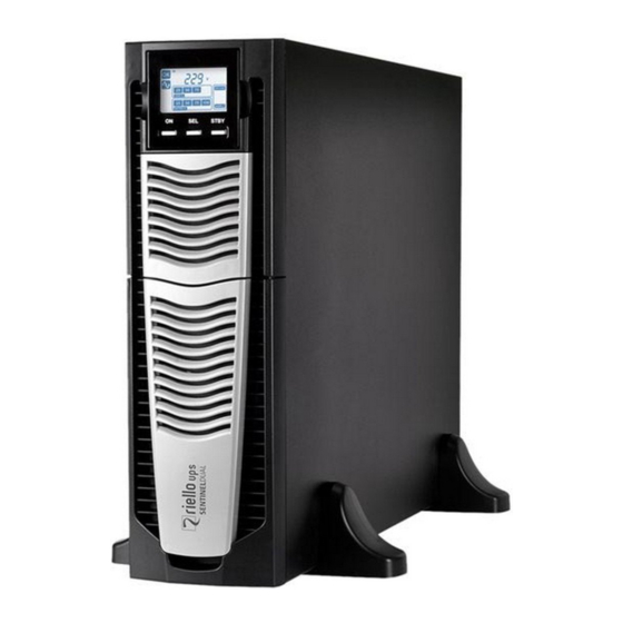
PRESENTATION SENTINEL DUAL Sentinel Dual is the best solution for powering mission critical applications and electro-medical devices requiring maximum power reliability. Flexibility of installation and use (digital display, user-replaceable battery set), as well as the many communication options available, makes the Sentinel Dual suitable for many different applications from IT to security. Up to 3 SENTINEL DUAL’s can be operated in parallel in either capacity or N+1 redundant configuration offering increased reliability for critical system. -
Page 7: Ups Views
UPS V IEWS RONT VIEW Models 5 – 6 kVA Models 8 – 10 kVA All models without front panel without front panel Extractable/rotatable display plate Battery pack connector Release slits Battery pack retention panel Removable front panel Cooling fan 1/0 Switch - 7 -... -
Page 8: Rear View
EAR VIEW Models 5 – 6 kVA Models 5 – 6 kVA Models 8 – 10 kVA with Power Distribution Battery expansion connector Parallel card slot Cooling fan IEC sockets (16A max) and overcurrent protection Communication Card Slots Protection box for IN/OUT connection EnergyShare sockets (10A max) and overcurrent Remote control terminal protection... -
Page 9: Display Panel View
ISPLAY PANEL VIEW “SEL” button Load level indicator “ON” button Configuration area “STAND-BY” button Maintenance request Regular operation Timer Mains operation Measurement display area Battery operation Stand-by / alarm Load powered by bypass EnergyShare Battery charge indicator - 9 -... -
Page 10: Battery Box ( Optional For Some Models )
ATTERY OPTIONAL FOR SOME MODELS The BATTERY BOX, with the same dimensions and aesthetic appearance of the UPS, is an accessory supplied as standard for some UPS models and optional for the others. The BATTERY BOX contains batteries which allow the operating time of the uninterruptible power supplies to be increased during extended blackouts. -
Page 11: Separate Bypass Input ( Only For "Di" Versions )
“DI” EPARATE YPASS NPUT ONLY FOR VERSIONS THE “DI” VERSION OF THE UPS SERIES HAS A BYPASS LINE SEPARATE FROM THE INPUT LINE. The UPS series with Separate Bypass allows for making a separate connection between the input line and the bypass line. The UPS output will be synchronised with the bypass line in such a way that there will not be any incorrect switching between push-pull voltages if the automatic bypass intervenes or the maintenance bypass switch (SWMB) is closed. -
Page 12: Installation
INSTALLATION NITIAL CONTENT CHECK After opening the packaging, it is first necessary to check the contents. The package must contain: UPS (and eventual BATTERY BOX) Safety manual + Quick start guide + Download card USB cable Support feet + extensions Handles for rack installation Handle screws Battery expansion plug... -
Page 13: Installation Environment
NSTALLATION ENVIRONMENT The UPS and the Battery Box must be installed in ventilated, clean environments which are sheltered from bad weather. The relative humidity in the environment must not exceed the maximum values shown in the Technical Data table. The ambient temperature, whilst the UPS is in operation, must remain between 0 and 40°C, and the UPS must not be positioned in places which are exposed to direct sunlight or to hot air. -
Page 14: Tower Version
OWER VERSION This chapter describes the steps for preparing the UPS and Battery Box for tower version use. ATTENTION: For your safety and that of the product, you must carefully follow the instructions given here below. BEFORE YOU CARRY OUT THE FOLLOWING SEQUENCE OF OPERATIONS, MAKE SURE THAT THE UPS IS COMPLETELY SWITCHED OFF AND NOT CONNECTED TO THE MAINS POWER SUPPLY OR TO ANY LOAD Once removed from the packaging, the UPS is already preset for installation in the tower configuration. -
Page 15: Tower Version With Battery Box
OWER VERSION WITH ATTERY BEFORE CARRING OUT THE FOLLOWING SEQUENCE OF OPERATIONS, ENSURE THAT: THE UPS IS COMPLETELY SWITCHED OFF AND NOT CONNECTED TO THE MAINS POWER SUPPLY OR TO ANY LOAD. THE BATTERY BOX IS DISCONNECTED FROM THE UPS, FROM ANY OTHER BATTERY BOXES AND WITH THE BATTERY ISOLATOR OPEN For the Battery Box version, each foot is composed of four parts: two supports and an extension. -
Page 16: Rack Version
ACK VERSION The sequence of operations to be followed in order to transform the UPS or Battery Box into rack version are described below. BEFORE CARRING OUT THE FOLLOWING SEQUENCE OF OPERATIONS, ENSURE THAT: THE UPS IS COMPLETELY SWITCHED OFF AND NOT CONNECTED TO THE MAINS POWER SUPPLY OR TO ANY LOAD. -
Page 17: Power Connection
OWER ONNECTION ALL OPERATIONS DESCRIBED IN THIS SECTION MUST BE PERFORMED BY QUALIFIED PERSONNEL ONLY. Our Company assumes no liability for damages caused by incorrect connections or operations not contained in this manual. The UPS has HAZARDOUS electrical voltages inside it, even when the input and/or battery switches are off. The inside of the UPS is protected by safety panels which should not be removed by untrained personnel. -
Page 18: Internal Protective Devices Of The Ups
NTERNAL ROTECTIVE EVICES OF THE Located within the UPS are fuses (not accessible) in order to protect the rectifier input stage, the output stage of the inverter and the batteries. The table below shows the values of the internal protection fuses. NOTE: the UPS internal bypass line is not protected by fuses. -
Page 19: External Protective Devices
XTERNAL ROTECTIVE EVICES LINE PROTECTION: MAGNETOTHERMAL or FUSE Within the UPS there are protection devices for output and internal faults. You must protect the input line (and the separate bypass line if present) with the appropriate protection devices. These devices must comply with the regulations of the country where the UPS is installed. -
Page 20: Connections
ONNECTIONS The first wire to be connected is the protective earth wire, which is to be inserted in the terminal marked PE. During operation the UPS must be connected to the earthing system Connect the input and output cables to the terminal board as shown in the figure below: Models 5-6 kVA Models 8-10 kVA Models 10 kVA with separate bypass “DI”... - Page 21 Models 8-10 kVA with three-phase input “TM” FOR CONNECTION TO A THREE-PHASE LINE WITH NEUTRAL, CONNECT THE THREE PHASES AND THE INPUT NEUTRAL TO “L1”, “L2”, “L3” AND “N”. MAKE SURE THAT THE SWITCH IS IN POSITION “↑ 3~”. FOR CONNECTION TO A SINGLE-PHASE LINE, CONNECT THE LIVE AND THE INPUT NEUTRAL TO “L1” AND “N”.
-
Page 22: Wiring Diagrams For Connecting To The Electrical System
IRING DIAGRAMS FOR ONNECTING TO THE LECTRICAL YSTEM UPS without any variation in neutral condition UPS with galvanic isolation at input UPS with galvanic isolation at output - 22 -... - Page 23 Separate bypass: if the separate bypass option “DI” is present, first remove the jumper between JP and L before to connect the bypass line. Note: the neutral of the main power supply line and the bypass line are connected within the UPS, therefore they must be referenced to the same potential.
- Page 24 Separate bypass with different lines: if the separate bypass option “DI” is present, first remove the jumper between JP and L before to connect the bypass line. Protective devices must be present on both the main power supply line and the bypass line. Note: the neutral of the main power supply line and the bypass line are connected within the UPS, therefore they must be referenced to the same potential.
-
Page 25: Battery Box Installation
ATTERY OX INSTALLATION ATTENTION: CONFIRM ON THE SPECIFICATION LABEL THAT THE VOLTAGE FROM THE BATTERY BOX IS THE SAME AS THAT ALLOWED BY THE UPS. THE CONNECTION BETWEEN THE UPS AND THE BATTERY BOX MUST BE MADE WITH THE BATTERY BOX FUSE HOLDERS OPEN. -
Page 26: Use
ONNECTIONS AND SWITCHING ON FOR THE FIRST TIME 1) Power on the UPS. 2) Press the 1/0 switch located under the removable front panel. 3) After a few moments, the UPS will switch on, the display will light up, there will be a beep and the icon will start to flash. -
Page 27: Display Panel Messages
ISPLAY PANEL MESSAGES This chapter describes, in detail, the various information that can be displayed on the LCD. STATUS MESSAGES ICON STATUS DESCRIPTION Fixed Indicates a fault Flashing The UPS is in stand-by mode Fixed Indicates regular operation Fixed The UPS is operating from the mains The UPS is operating from the mains, but the output voltage is not Flashing synchronised with the mains voltage... -
Page 28: Measurement Display Area
EASUREMENT DISPLAY AREA The front panel can be used to display important UPS operating information. When the UPS is switched-on, the display shows the main voltage value. To display a different measurement, press the “SEL” button repeatedly until the desired measurement appears. In the event of a fault/alarm (FAULT) or a lock (LOCK), the display will automatically show the type and code of the corresponding alarm. - Page 29 NDICATIONS ON THE DISPLAY FOR WITH THREE PHASE CONNECTION DESCRIPTION DESCRIPTION GRAPHIC EXAMPLE GRAPHIC EXAMPLE Battery charge Phase 1 voltage percentage Phase 2 voltage Total battery voltage Phase 3 voltage Applied load percentage Current absorbed by the UPS output voltage load UPS internal Output voltage frequency...
-
Page 30: Operating Mode Configuration
PERATING ODE CONFIGURATION The area of the display shown in the figure displays the active operating mode and allows the user to choose other modes directly from the display panel. HOW TO PROCEED: To access the configuration area, hold down the “SEL” button for at least 3 seconds. ... -
Page 31: Redundant Auxiliary Power Adapter For Automatic Bypass
PROGRAMMABLE AUXILIARY SOCKETS (EnergyShare) The EnergyShare sockets are outlets that allow for the automatic disconnection of the load applied to them in certain operating conditions. The events that determine automatic disconnection of the EnergyShare sockets can be selected by the user through the configuration software. -
Page 32: Battery Pack Replacement ( Only For 5 - 6 Kva)
5 - 6 ATTERY PACK REPLACEMENT ONLY FOR The UPS is also equipped with a dedicated battery pack that allows for easy replacement of batteries (hot swap) in complete safety, thanks to the protected connection system. WHEN THE BATTERY PACK IS DISCONNECTED, THE LOADS CONNECTED TO THE UPS ARE NOT PROTECTED IN THE EVENT OF A MAINS FAILURE ... - Page 33 Remove the battery pack's retention panel carrying out the operations shown in the figure below. Slip off the battery pack pulling it towards the outside, as shown in the figure below. Be careful when extracting and lifting up the battery pack as it is heavy. ATTENTION: the new battery pack must contain the same number and type of batteries (see the label located on the battery pack near the connector).
-
Page 34: Software
OFTWARE CAUTION: If the RS232 communication port is used, it is not possible to communicate with the USB port and vice versa. It is advisable to use a cable which is shorter than 3 metres for communication with the UPS. To obtain additional communication ports with different functions, independent from the standard USB and RS232 ports on the UPS, various accessories are available which can be inserted into the communication card slot. -
Page 35: Ups Configuration
CONFIGURATION The table below illustrates all the possible configurations available to the user in order to best adapt the UPS for individual requirements. It is possible to perform these operations using the configuration software. FUNCTION DESCRIPTION DEFAULT Operating mode Selects the operating modes ON LINE Selects the rated output voltage Output voltage... - Page 36 FUNCTION DESCRIPTION DEFAULT Disabled (load NOT Bypass active in stand-by Load supply from bypass with UPS in stand-by supplied) Selects the accepted range for the input frequency for Bypass frequency tolerance switching to the bypass and for the synchronisation of the ±...
-
Page 37: Communication Ports
OMMUNICATION PORTS On the back of the UPS (see UPS Views), the following communication ports are present: RS232 connector USB connector Expansion slot for additional communication cards RS232 CONNECTOR RS232 CONNECTOR PIN # SIGNAL NOTES Programmable OUTPUT #3 *: [default: UPS in lock] (*) Opto-isolated contact max. -
Page 38: Troubleshooting
TROUBLESHOOTING An irregular operation of the UPS is frequently not due to malfunctions, but to simple problems, inconveniences or distractions. Therefore, the user is advised to consult the table below providing useful information on how to solve the most common problems. - Page 39 PROBLEM POSSIBLE CAUSE SOLUTION THE JUMPER IS MISSING THE DISPLAY SHOWS Assemble the jumper or make sure that it is inserted FROM THE R.E.P.O. THE FOLLOWING CODE: CONNECTOR OR IT IS NOT correctly. INSERTED CORRECTLY MAINTENANCE BYPASS Open the isolator (SWMB). ISOLATOR (SWMB) CLOSED THE DISPLAY SHOWS THE FOLLOWING CODE:...
- Page 40 PROBLEM POSSIBLE CAUSE SOLUTION PROTECTION DEVICE Restore the protection device upstream. WARNING: UPSTREAM FROM THE check that there is no overload or short circuit at the BYPASS LINE OPEN (ONLY IF output of the UPS THE DISPLAY SHOWS BYPASS IS SEPARATE) THE FOLLOWING CODE: BYPASS ISOLATOR OPEN Close the isolator.
- Page 41 PROBLEM POSSIBLE CAUSE SOLUTION It is recommended to replace the batteries of the UPS, THE DISPLAY SHOWS since they ate no longer able to maintain the charge for THE BATTERIES HAVE THE FOLLOWING CODE: a sufficient autonomy. FAILED THE PERIODIC EFFICIENCY TEST Warning: The replacement of the batteries must be carried out by qualified personnel.
-
Page 42: Status Alarm Codes
TATUS ALARM CODES By using a sophisticated self-diagnostic system, this UPS can check and indicate on the display panel its status and any error and/or fault occurred during operation. Whenever a problem arises, the UPS signals the event by showing the code and the corresponding alarm on the display. - Page 43 Faults: These are more critical problems compared to the “Anomalies”, as if they persist they may bring the UPS to a halt even in a very short time. CODE DESCRIPTION Internal communication error Phase1 input fuse blown Phase2 input fuse blown or input relay locked (will not close) Phase3 input fuse blown or input relay locked (will not close) Precharge of positive branch condensers failed Precharge of negative branch condensers failed...
-
Page 44: Technical Data
TECHNICAL DATA UPS MODELS 5 kVA 6 kVA 8 kVA 10 kVA SINGLE-PHASE INPUT Nominal voltage [Vac] 220 – 240 (1P+N+PE) Maximum operating voltage [Vac] Nominal frequency [Hz] 50 - 60 Accepted tolerance for input voltage 20% @ 100% load without activation of battery -40% +20% @50% load Accepted tolerance for input frequency... - Page 45 OTHER DATA Leakage current towards ground [mA] < 1,5 ≤ 1,7 Room temperature [°C] 0 – 40 Humidity < 90% without condensation excessive battery discharge - over current - short circuit - over Protection devices voltage - under voltage - thermal 131 x 640 x 448 - Tower 2 x (131 x 640 x 448) –...
- Page 46 - 46 -...