Table of Contents
Table of Contents

Related Manuals for Riello UPS SENTINEL DUAL Series


Summary of Contents for Riello UPS SENTINEL DUAL Series
- Page 2 SAFETY This part of the manual contains precautions that must be adhered to strictly since they regard SAFETY. a) THE UPS MUST NOT OPERATE WITHOUT AN EARTH CONNECTION. The first connection to be carried out is the earth conductor, which has to be connected to the terminal marked b) Avoid connecting the output neutral to the input neutral or to earth as this could cause malfunctions.
- Page 3 Thanks you for choosing this product of the Sentinel Dual range. Riello UPS are renowned specialists in the development and production of uninterruptible power supplies (UPS). The UPS in this range are high quality products, designed and built with care in order to give you the best performance.
-
Page 4: Table Of Contents
ONTENTS PRESENTATION UPS V IEWS ATTERY IEWS DISPLAY MASK VIEW NSTALLATION PENING THE PACKAGING AND CHECKING ITS CONTENTS OWER VERSION ACK VERSION NSTALLATION PROCEDURES BATTERY BOX ONNECTING THE TO THE ONNECTIONS 8-10kVA single phase version Three phase version Version with external Bypass remote control IRST START TART UP FROM MAINS... -
Page 5: Presentation
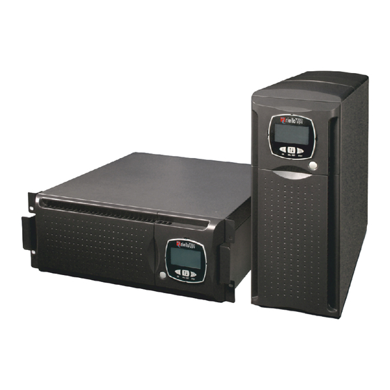
PRESENTATION The new Sentinel Dual UPS family has been designed with a special eye to versatility. These UPSs can in fact be installed either in a tower version or in a rack version, according to requirements. The 2 different versions of the product are shown below: Tower Rack SDL 8000... -
Page 6: Ups Views
PRESENTATION UPS V IEWS Release slots Rotatable display mask Manual bypass switch General switch Removable front panel Front view (with front panel removed) (with front panel) Battery expansion connector Remote emergency power Cooling fan off (R.E.P.O.) COMMUNICATION expansion slot RS232 communication port USB communication port IEC 10 A Power... -
Page 7: Battery Box Views
PRESENTATION ATTERY IEWS Release slots Extractable/rotatable mask Removable front panel Front view Ventilation grille Connectors for battery Fuse-holder expansion disconnecting switches Rear view... -
Page 8: Display Mask View
PRESENTATION DISPLAY MASK VIEW “SEL / SET” button “ON” button “STBY” button Display Normal operation Configuration area Operation from mains Maintenance request Operation from battery Timer Load powered by the bypass Measurement display area Battery back up time indicator Stand-by/alarm Load level indicator... -
Page 9: Installation
NSTALLATION PENING THE PACKAGING AND CHECKING ITS CONTENTS After opening the packaging, first check the contents. The packaging should contain the following: Battery box 1 cable guide + 2 seal stops 6 plastic covers (upper panels UPS and Battery box) Ferrules for cables - terminal board connection 2 plastic keys to release display 2 Handles kits... - Page 10 NSTALLATION UPS-Battery box connection cable 2 Fuses for Battery box - 14x51 mm, 50A, 400V User manual + CD-ROM software...
-
Page 11: Tower Version
NSTALLATION WARNING: this UPS product conforms to the current electromagnetic compatibility (EMC) regulations (C2 class). It may cause radio interference in the home environment. The user may have to adopt supplementary measures. OWER VERSION This chapter describes the operations required to prepare the UPS and the Battery box for use in the tower version. -
Page 12: Rack Version
NSTALLATION ACK VERSION The sequence of operations required to convert the UPS and the Battery box into the rack version is described below. WARNING: for your safety and that of your product, the information set out below should be followed carefully. -
Page 13: Installation Procedures
NSTALLATION 6 - At this point, with the UPS and the Battery box in a horizontal position, fasten the handles to the sides of the UPS and Battery box with the screws as shown in the figures below. NOTE: The UPS and Battery box are compatible for mounting in standard rack cabinets of 600mm x 800mm or more (in width). -
Page 14: Connecting The Ups To The Battery Box
NSTALLATION BATTERY BOX ONNECTING THE TO THE Connect the UPS to the Battery box by means of the expansion cable provided (see figure below) Insert the two fuses provided into the fuse-holder disconnecting switches at the back of the Battery box. -
Page 15: Use
ONNECTIONS INSTALLATION MUST BE CARRIED OUT EXCLUSIVELY BY QUALIFIED PERSONNEL. THE FIRST CONNECTION TO BE CARRIED OUT IS THE PROTECTION CONDUCTOR (EARTH CABLE), TO BE INSERTED IN THE TERMINAL MARKED THE UPS MUST NOT BE OPERATED WITHOUT BEING CONNECTED TO THE EARTHING SYSTEM. Warning: if the neutral (N) and phase (F) instructions are observed for the plugs and sockets, the UPS will not change the existing neutral arrangements when inserted in a system. -
Page 16: 8-10Kva Single Phase Version
8-10kVA single phase version 1. Use 3 cables with 10 mm section (EARTH, N and L) in input, and 3 cables with 10 mm section for the output (EARTH, N and L). With reference to the figure shown at the side: - Insert the cables from the 63A magneto-thermal switch into seal stop P2 (input line). -
Page 17: Three Phase Version
Three phase version 1. (8-10kVA THREE PHASE VERSION): Use 3 cables with 6 section (EARTH, L2 and L3) and 2 with 10 mm section (N, L1) in input (N.B.: L1 and N have a greater section because in operation from bypass they have to carry all the input current). -
Page 18: Version With External Bypass Remote Control
Version with external Bypass remote control If it is required to make the Bypass remote maintenance control external, follow points 1, 2 and 3 as described above. Then continue as shown below: Remove the plug from the first hole at the top of the removable drawer and mount the cable guide provided. - Page 19 Secure the cable guide and the seal stop to the flange, close the drawer and secure it with the screw removed previously. A WARNING LABEL MUST BE AFFIXED TO ALL MAINS POWER ISOLATING SWITCHES INSTALLED FAR FROM THE UPS AREA, IN ORDER TO REMIND SUPPORT SERVICE PERSONNEL THAT THE CIRCUIT IS CONNECTED TO A UPS. THE LABEL MUST CARRY THE FOLLOWING MESSAGE: ISOLATE THE UNINTERRUPTIBLE POWER SYSTEM (UPS) BEFORE WORKING ON THIS CIRCUIT...
-
Page 20: First Start - Up
IRST START 1) Ensure that all the operations described in the paragraph above, “Connections”, have been carried out correctly. 2) Close the magneto-thermal switch located upstream of the UPS. 3) Press the general switch located on the front panel. 4) The UPS will start up after a few seconds; the display will come on, a beep will be emitted and the icon will flash. -
Page 21: Display Panel Indications
ISPLAY PANEL INDICATIONS This section describes in detail all the information that can be shown on the LCD display. In order to make it clearer, all the information displayed can be divided into three main groups: UPS status indicators Measurements display area Configuration area UPS status indicators ICON... -
Page 22: Measurements Display Area
Measurements display area The most important measurements relating to the UPS can be shown in sequence on the display. When the UPS is started up, the display shows the value of the mains voltage. To go to a different display press the “SEL/SET” button repeatedly until the required measurement is displayed. -
Page 23: Three Phase Version
Three phase version Some examples are shown below: GRAPHIC EXAMPLE DESCRIPTION GRAPHIC EXAMPLE DESCRIPTION Percentage of battery charge Voltage phase 1 Total battery voltage Percentage of the applied load Voltage phase 2 Current absorbed by the load Temperature of the cooling system for the UPS internal electronics Voltage phase 3... -
Page 24: Configuration Area
Configuration area The configuration area groups together the main UPS operating parameters and displays its current status. The parameters contained in this area can be changed directly from the display panel. SETTABLE PARAMETERS: Frequency: Output voltage frequency Frequency Voltage: Output voltage Voltage Mode: UPS operating mode Mode... -
Page 25: Operating Modes
PERATING MODES The mode that ensures maximum protection to the load is ON LINE mode (default), where the energy for the load undergoes a double conversion and is reconstructed fully sinusoidal in output with frequency and voltage set by accurate digital microprocessor control independently of the input (V.F.I.). * The following modes can be set in addition to the conventional ON LINE double conversion operating mode: ECO (LINE INTERACTIVE) -
Page 26: Ups Configuration
CONFIGURATION The following table shows all the possible configurations available to adapt the UPS to the user’s requirements. KEY: Indicates that the configuration can be changed from the display panel as well as by means of the configuration software. Indicates that the configuration can only be changed via the configuration software. - Page 27 FUNCTION DESCRIPTION PREDEFINED POSSIBLE CONFIGURATIONS MODE Alarm threshold Selects the user • Disabled for maximum Disabled overload limit • 0 ÷ 103 in 1% steps load Selects the level of Display brightness of the LCD Maximum Minimum ÷ Maximum in 20 steps brightness display Selects the operating...
-
Page 28: Communication Ports
OMMUNICATION PORTS The following communication ports are located at the back of the UPS (see UPS Views): Serial port, available with RS232 connector and USB connector. NOTE: use of one connector automatically excludes the other. Expansion slots for additional COMMUNICATION SLOT interface cards. RS232 and USB connectors RS232 CONNECTOR USB CONNECTOR... -
Page 29: Software
OFTWARE Monitoring and control software The PowerShield software provides effective and intuitive management of the UPS, displaying all the most important information, such as input voltage, load applied, and battery capacity. It is also able to automatically effect operations such as shutdown, transmission of e-mails, SMS and network messages when particular events that can be selected by the user occur. -
Page 30: Troubleshooting
ROUBLESHOOTING Irregular functioning of the UPS is most often not an indication of a fault but due simply to trivial problems, minor difficulties or carelessness. We therefore recommend that you refer to the table below which gives a summary of useful information to solve the most common problems. - Page 31 TROUBLESHOOTING PROBLEM POSSIBLE CAUSE SOLUTION THE BUZZER SOUNDS CONTINUOUSLY AND THE Reduce the load to within the threshold of 100% (or THE LOAD APPLIED TO THE DISPLAY SHOWS ONE OF user threshold in the case of code A54). UPS IS TOO HIGH THESE CODES: A54, F50, F51, F52, F55, L50, L51, L52 THE DISPLAY SHOWS THE...
-
Page 32: Alarm Codes
TROUBLESHOOTING ALARM CODES Using a sophisticated self check system, the UPS can verify and indicate on the display panel any faults and/or malfunctions that may occur during the normal operation of the device. In the event of a problem, the UPS indicates this by displaying the code and the type of alarm (FAULT and/or LOCK). - Page 33 TROUBLESHOOTING Active controls: indicate the presence of an active remote control. CODE DESCRIPTION Shutdown remote control Load on bypass remote control Startup remote control Battery test underway LOCK LOCK signals are usually preceded by an alarm signal and, due to their significance, cause the inverter to shut down and the load to be powered via the bypass line (this procedure does not include locks from strong and persistent overloads or locks due to short circuits).
-
Page 34: Technical Data Table
ECHNICAL DATA TABLE INGLE SINGLE PHASE TECHNICAL DATA TABLE MODELS SDL 8000 SDL 10000 INPUT Nominal voltage 220/230/240 Vac Accepted range 0 - 280 Vac Voltage range for non-intervention of battery Maximum voltage 276Vac Minimum voltage: from 184 to 138 Vac from 100% to 50% of the linear load Return of operation from mains at 190Vac Nominal frequency 50 - 60 Hz ±5Hz... -
Page 35: Three / Single Phase Ups Technical Data Table
ECHNICAL DATA TABLE HREE SINGLE PHASE TECHNICAL DATA TABLE MODELS SDL 6500 TM SDL 8000 TM SDL 10000 TM INPUT (3 Ø + N star-configured voltages) Nominal voltage 220/230/240 Vac Accepted range 0 - 280 Vac Voltage range for non-intervention of battery Maximum voltage 276Vac Minimum voltage: from 184 to 138 Vac from 100% to 50% of the linear load... -
Page 36: Battery Box Technical Data Table
ECHNICAL DATA TABLE ATTERY OX TECHNICAL DATA TABLE BASIC MODELS BBX SDL 240V BB NP A3 BBX SDL 240V BB NP A5 BATTERY Nominal voltage [Vdc] End of charge voltage [Vdc] No. of batteries/V 20 / 12 SUNDRY Ambient temperature (1) [°C] 0 –...