Table of Contents
Table of Contents

Related Manuals for SainSmart Genmitsu 3020-PRO MAX


Summary of Contents for SainSmart Genmitsu 3020-PRO MAX
- Page 1 Genmitsu 3020-PRO MAX CNC Router V1.0 Sept. 2021...
- Page 2 Welcome Disclaimer Specifications 1 – Unboxing 2 – Mechanical Assembly 3 – Wiring 4 – Software Setup...
- Page 3 Thank you for purchasing the Genmitsu 3020-PRO MAX CNC Router from SainSmart. Included in your package is a pre-loaded USB Stick, on this you will find: ● PDF version of this manual ● Windows USB Driver ● GrblControl/Candle software for Windows ●...
- Page 4 Always place the CNC Machine on a stable surface. ● The SainSmart Genmitsu CNC Machine is supplied with Switchable Power Supply 230VAC or 115VAC. Never use a different power supply; it may cause malfunctions or damage to the machine. ●...
- Page 5 Work Area 300 x 200 x 72mm (11.81 x 7.87 x 2.83inch) Drive System Linear Rail Guide & T nut Screw Control Board Compatibility GRBL 1.1f Stepper Driver A4988 Stepper Motors 42 x 48mm Spindle 300W/12000RPM Accuracy ±0.1mm Power Supply 48V/7.3A CAM Software Candle, Carveco Maker, Easel and more...
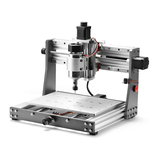
- Page 6 Spindle with ER11 Tail Base Assembly X-axis/Z-axis Gantry (300W/12000RPM)
- Page 7 Electrical Parts List 1 × Spindle Cable 3 × Stepper Motor Cable Controller Board USB Cable (1.5m) USB Flash Disk (4G) Power Supply (48V/7.3A) Offline Controller...
- Page 8 Tools/Accessories Parts List Allen Wrench Set 3 x Limit Switch Emergency Stop Button Cable Protector (2m) (1.5mm, 2mm, 2.5mm, (60cm) with Cable (60cm) 3mm, 4mm, 5mm) 2 x Cable Tie Laser Mount 4 x Clamp Cleaning Brush (33mm) (14*87*2mm, 17*88*2mm) 10 ×...
- Page 9 Screws/Other Parts List 4 x M5*10 Screw 16 x M5*16 Screw 4 x M4*10 Screw 4 x M4 T Slot Nut 16 x Spring Loaded 4 x M2.5*10 Screw 4 x M2.5*12 Screw 4 x M5 T Slot Nut M5 T Nut...
- Page 10 Optional Accessories (Not Included) 2PCS T-Track EM10B, 1/8" Shank, EM03A, 1/8" Shank, 5.5W Fixed Focus Mini Hold Down Single Flute Ball Nose Chromatic End Mill Laser Module Clamp Kit V-Groove CNC Cutter Cutter Set Scan QR codes to learn more...
- Page 11 Part 2 - Mechanical Assembly Before we begin, place your 3020-PRO MAX CNC Base on a flat and level surface. Step 1:Align the X / Z-axis Gantry Fixing Nuts Base Assembly 16 x Spring Loaded M5 T Nut Insert Spring loaded M5 T Nuts into the side of the profile. Do this by tilting the T Nut at Step diagram for putting an angle as shown in the diagram below with the tapered side into the slot, be sure the the nuts into the profile:...
- Page 12 Step 2:Install the X / Z-axis Gantry X-axis/Z-axis Gantry 16 x M5*16 Screw After you align the gantry with the nut holes, tighten the M5*16 Screws, before completely tightening, ensure the back of the gantry is spaced 13mm from the back of the machine frame on both sides (See Diagram Below). X-axis/Z-axis Gantry M5*16 Screw...
- Page 13 Step 3:Install the Rubber Feet What you will need 4 x Rubber Feet 4 x M4*10 Screw 4 x M4 T Slot Nut Place the M4 T Slot Nut into the profile, align the Rubber Feet with the screw hole, adjust the Rubber Feet position, and then tighten the M4*10 Screw.
- Page 14 Step 4:Install the Limit Switches What you will need 4 x M2.5*10 Screw 4 x M2.5*12 Screw 3 x Limit Switch (60cm) Align the X-axis, Y-axis and Z-axis limit switches with the screw holes and tighten the M2.5 Screws. For the Z-axis one, please use the M2.5*10 Screw, for the X-axis and Y-axis, use the M2.5*12 Screws. M2.5 Screws Limit Switch...
- Page 15 Step 5:Install the Control Board Controller Board 4 x M5*10 Screw 4 x M5 T Slot Nut 1. Place the M5 T Slot Nut into the Y-axis profile. 2. Align the Control Board with the nut hole, tighten the M5*10 Screw into the hole and adjust the control board position, then tighten the screw.
- Page 16 STEP 6:Install the Spindle What you will need Spindle with ER11 Tail (300W/12000RPM) 1. Loosen the M5 Hex Screws of the spindle motor holder. 2. Insert the spindle into the spindle motor holder, tighten the M5 Hex Screws, adjust the spindle height so it sits about centered in the holder, and then tighten the screws.
- Page 17 Completed View...
- Page 18 Tips Clamps Installation View For good measure, lubricate the lead screws and guide rails for each axis. This will reduce running noise and extends the lifespan of your CNC.
- Page 19 Reset 5V Out Z-Probe Offline Controller Limit Switch Power Switch USB Interface Emergency Stop Z-axis Motor Y1-axis Motor Y2-axis Motor X-axis Motor -Spindle+ -Power Supply+...
- Page 20 1. Connect the Limit Switches: Plug the X, Y, Z limit switch cable into X-, Y-, Z- port of the control board. There is a spare Z-limit switch for replacement. X-axis limit Y-axis limit Z-axis limit...
- Page 21 2. Connect the Stepper Motors: Plug the X, Y, Z motor cables into the X- Motor, Y-Motor and Z-Motor port. (There are two ports for connecting the Y axis motor, one is reserved for a Rotary 4th axis, you can plug into either Y axis port.) Y-axis Motor Z-axis Motor X-axis Motor Z-axis Motor...
- Page 22 3. Connect the Spindle Motor: Connect the Z-axis motor cable to the extension cable, and then plug the other end of the extension cable into the Spindle+ and Spindle- and then tighten the screws. Spindle + Spindle - Red -Red Black -Black...
- Page 23 Connect the Emergency Stop Switch: Insert the emergency switch cable into the E-stop port of the motherboard and check whether the emergency stop switch is in the disconnected state. (Note: Pushing the button will trigger an emergency stop. The button will stay engaged once pushed. The button can only be released when twisted clockwise. This prevents double pushing the button from releasing the trigger.) Connect the Power Supply: Connect the power red cable to the Power+ port and the black cable to the Power- port.
- Page 24 Driver Installation Install drivers (software Driver CH340SER.exe)
- Page 25 • Windows XP: Right click on "My Computer", select "Manage", select "Device Manager". Windows 7, 8 and 10: Click "Start", Right click "Computer", Select "Manage", Select "Device Manager" from left pane. • In the tree, expand "Ports (COM & LPT)" •...
- Page 27 Copyright © 2021 by SainSmart All rights reserved. This manual or any portion thereof may not be reproduced or used in any manner whatsoever without the written permission of the publisher, except for the use of brief quotations embodied in critical reviews...
- Page 28 Genmitsu Desktop CNC & Laser www.sainsmart.com [email protected] Vastmind LLC, 5892 Losee Rd Ste. 132, N. Las Vegas, NV 89081...