Table of Contents
Quick Links
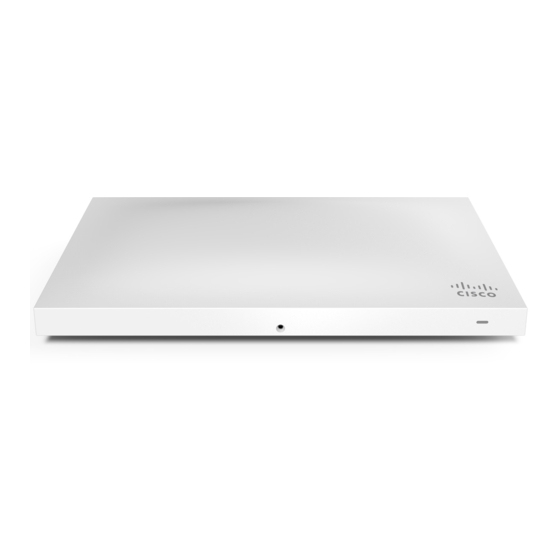
MR42 Installation Guide
The Cisco Meraki MR42 is a dual-band enterprise class 802.11ac cloud-managed access point. Designed for high capacity and high density, the MR42 meets
the needs of the most demanding environments, and also includes the first ever cloud-managed third radio dedicated to optimizing the RF environment
and securing the airwaves.
About this Guide
This guide provides instruction on how to install and configure your MR42 access points. This guide also provides mounting instructions and limited
troubleshooting procedures. For more wireless installation guides, refer to the
Product Overview
Physical Specifications
Interfaces
•
1x 10/100/1000 BASE-T Ethernet (RJ45)
•
1x DC power connector (5.5 mm x 2.5 mm, center positive)
Power
•
Power over Ethernet: 37 - 57 V (802.3at required with functionality-restricted 802.3af
mode supported)
•
Alternative: 12 V DC input
•
Power consumption: 20W max (802.3at)
•
Power over Ethernet injector and DC adapter sold separately
Environment
•
Operating temperature: 32 °F to 104 °F (0 °C to 40 °C)
•
Humidity: 5 to 95% non-condensing
Physical Security
•
Two security screw options (included) (10 mm long and 2.5 mm diameter and 4.7 mm
head)
MR42
wireless installation guides section
on our documentation website.
1
Table of Contents

Related Manuals for Cisco Meraki MR42


Summary of Contents for Cisco Meraki MR42
- Page 1 MR42 Installation Guide The Cisco Meraki MR42 is a dual-band enterprise class 802.11ac cloud-managed access point. Designed for high capacity and high density, the MR42 meets the needs of the most demanding environments, and also includes the first ever cloud-managed third radio dedicated to optimizing the RF environment and securing the airwaves.
- Page 2 • Kensington lock hard point • Concealed mount plate with anti-tamper cable bay Product View and Physical Features Your Meraki MR42 has the following features:...
- Page 3 The mount cradle has the following features:...
- Page 4 Security Features The MR42 features multiple options for physically securing the access point after installation: 1. Security screw – The accessory kit includes screws that can be used to secure the access point to the mount cradle. Engaging the security screw prevents accidental dislodging and theft. 2.
-
Page 5: Package Contents
Power Source Options The MR42 access point can be powered using either the Meraki AC Adapter, PoE Injector (both sold separately), or a third-party PoE switch. The MR42 will function in low power mode when powered by a 802.3af power source. While in low power mode, the MR42 will disable its Air Marshal radio as well as two out of three transmit streams on the 2.4 Ghz band. - Page 6 • Mount cradle including built-in level tool • Drop ceiling mount kit...
- Page 7 • Wall screws, wall screw anchors, and security screws • Spare hardware Safety and Warnings These operations are to be taken with respect to all local laws. Please take the following into consideration for safe operation: • Power off the unit before you begin. Read the installation instructions before connecting the system to the power source.
- Page 8 1. Login to http://dashboard.meraki.com. If this is your first time, create a new account. 2. Find the network to which you plan to add your APs or create a new network. 3. Add your APs to your network. You will need your Meraki order number (found on your invoice) or the serial number of each AP, which looks like Qxxx-xxxx-xxxx, and is found on the bottom of the unit.
- Page 9 Static IP via DHCP Reservations Instead of associating to each Meraki AP individually to configure static IP addresses, an administrator can assign static IP addresses on the upstream DHCP server. Through “DHCP reservations,” IP addresses are “reserved” for the MAC addresses of the Meraki APs. Please consult the documentation for the DHCP server to configure DHCP reservations.
-
Page 10: Installation Instructions
2. Power over Ethernet supports a maximum cable length of 300 ft (100 m). 3. If being used in a mesh deployment, the MR42 should have line of sight to at least two other Meraki devices. A Cisco Partner can help ensure that your AP placement is ideal. Install the MR42 For most mounting scenarios, the MR42 mount cradle provides a quick, simple, and flexible means of mounting your device. - Page 11 • 6-32x7 mm screws only used for recessed rail mount (uncommon) • 2 rubber spacers 1. Attach the T-rail clips to the T-rail by rotating them and snapping them into place as shown. The black foam pads should be compressed slightly after installation.
- Page 12 2. Using the dashed lines on the mount cradle template as a guide, set the proper spacing of the T-rail clips on the T-rail. 3. Tighten the set screws on the T-rail clips to secure the clips using a 5/64”(2 mm) hex key.
- Page 13 4. Attach the mount cradle to the T-rail clips using the mount cradle holes (marked with a “T“). Tip: Pre-assemble rubber spacers and screws to the mount cradle. The mount cradle can then be held with one hand while the other hand holds a screwdriver.
- Page 14 Then adjust the MR42 to guide the MR42’s bottom slot into the cradle’s bottom tab until it clicks into place. Once in place, the MR42 should be secured to the cradle by using one of the included screws in the cradle’s bottom tab. To release the MR42 from the mount cradle, first remove the security screw that secures the MR42 to the cradle’s bottom tab.
-
Page 15: Verify Device Functionality And Test Network Coverage
Security Screw Install the security screw in the lower mount cradle tab. Kensington Lock Attach a Kensington lock cable to the access point at the hard point on the side of the device. Attach the other end of the cable to a secure location, such as a pipe or building fixture. Verify Device Functionality and Test Network Coverage 1. -
Page 16: Warranty
If you are still experiencing hardware issues, please contact Cisco Meraki support by logging in to dashboard and using the Help option near the top of the page, then opening and email case or calling using the contact information on that page. - Page 17 Meraki MR42 devices have been tested and found to comply with the limits for a Class B digital device, pursuant to part 15 of the FCC rules. These limits are designed to provide reasonable protection against harmful interference in a residential installation. This equipment generates, uses and can radiate radio frequency energy and, if not installed and used in accordance with the instructions, may cause harmful interference to radio communications.