Table of Contents
Quick Links
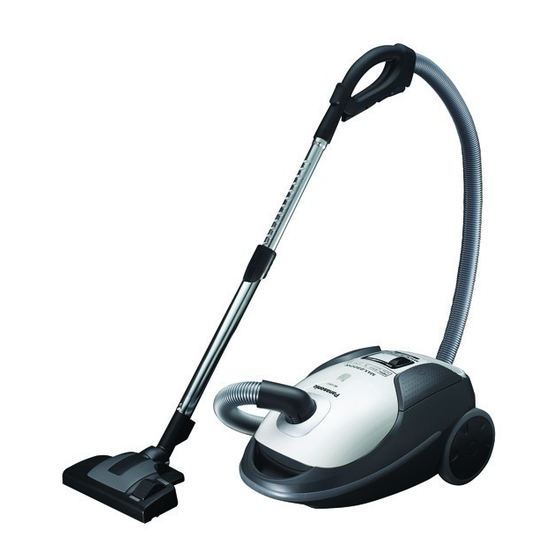
MC-CJ917-K747
Model No.
MC-CJ917-K149
MC-CJ917-K147
MC-CJ917-W747
MC-CJ917-W149
MC-CJ917-W147
Product Color : (K) Black , (W) White
Destination :
1.Saudi Arabia, Kuwait
MC-CJ917-K747
MC-CJ917-W747
2.Iran
MC-CJ917-K149
MC-CJ917-W149
3.UAE
MC-CJ917-K147
MC-CJ917-W147
© Panasonic Corporation 2011 Unauthorized copy-
ing and distribution is a violation of law.
Order Number VCB1109004CE
Vacuum Cleaner
Table of Contents

Related Manuals for Panasonic MC-CJ917-K747


Summary of Contents for Panasonic MC-CJ917-K747
- Page 1 MC-CJ917-K149 MC-CJ917-K147 MC-CJ917-W747 MC-CJ917-W149 MC-CJ917-W147 Product Color : (K) Black , (W) White Destination : 1.Saudi Arabia, Kuwait MC-CJ917-K747 MC-CJ917-W747 2.Iran MC-CJ917-K149 MC-CJ917-W149 3.UAE MC-CJ917-K147 MC-CJ917-W147 © Panasonic Corporation 2011 Unauthorized copy- ing and distribution is a violation of law.
-
Page 2: Table Of Contents
TABLE OF CONTENTS PAGE PAGE 1 Specifications ------------------------------------------------------3 2 Location of Controls and Components--------------------4 3 Troubleshooting Guide------------------------------------------5 4 Disassembly and Assembly Instructions -----------------7 4.1. Disassembly of the Dust Cover Assy -----------------7 4.2. Disassembly of the Dust Bag Holder------------------8 4.3. Disassembly of Body Cover Assy, Switch Pedal, Cord Rewind Button------------------------------9 4.4. -
Page 3: Specifications
1 Specifications... -
Page 4: Location Of Controls And Components
2 Location of Controls and Components... -
Page 5: Troubleshooting Guide
3 Troubleshooting Guide CONDITION CHECKPOINT FIGURE CHECK METHOD REMEDY The Motor CORD REEL • Check the continuity at both • If there is no continuity, replace the Cord Reel Unit, or the Rail doesn’t rotate. UNIT ends of the Plug and both ends RAIL BASE of the Lead Wire Terminal of Base Unit. - Page 6 CONDITION CHECKPOINT FIGURE CHECK METHOD REMEDY ON/OFF • Check the continuity by press- • If there is a problem, replace SWITCH ing the On/Off Switch. the P.C.B. Assy. (in the P.C.B. Assy) 1. The Motor TRIAC (on the • Check that the Triac has not •...
-
Page 7: Disassembly And Assembly Instructions
4 Disassembly and Assembly Instructions Important: Always turn the vacuum cleaner is power off before replacing components. Remove the power cord and plug from the mains. * Attention (1) When disassembling the vacuum cleaner, check the connections and wiring (pulling) of each component, and ensure that everything is restored correctly once repairs are complete. -
Page 8: Disassembly Of The Dust Bag Holder
Disassembly of the Dust Bag 4.2. Holder 1. Remove the Dust Bag Holder by inserting a slotted screwdriver into the mount of the Dust Bag Holder on the Lower Body Unit. Fig.2 Caution (There is a Spring inside) * When replacing the Dust Bag Holder, disassemble and replace the Spring mounted inside. -
Page 9: Disassembly Of Body Cover Assy, Switch Pedal, Cord Rewind Button
4.3. Disassembly of Body Cover Assy, Switch Pedal, Cord Rewind Button 1. Remove the Filter Case Fig.4 2. Remove 3 screws and disassemble the Body Cover Assy Fig.5... -
Page 10: Disassembly Of Upper Body, Handle Cover, And Guide Lever
4.4. Disassembly of Upper Body, 3. Disassemble the Switch Pedal/Cord Rewind Button toward the direction of the arrow Handle Cover, and Guide Lever Caution: (Spring is placed inside.) *Be careful not to lose the Spring. 1. Disassemble the Body Cover Assy and Switch Pedal as described in (4.3). - Page 11 3. Slide the Switch, and push it inward at the position 5. Disassembly of Handle Cover shown in the figure. Disassemble the Handle Cover from the Upper Body. Fig.11 6. Disassembly of Guide Lever Slide and disassemble the Guide Lever to the direc- Fig.9 4.
-
Page 12: Disassembly Of Motor Case Set
4.5. Disassembly of Motor Case Set 4.6. Disassembly of Cord Reel Unit 1. Disassemble the Rear Cover to the direction of the 1. Release the pretension of the Cord Reel Unit slowly arrow, and disassemble the Motor Case Set pulling by holding on the Power Plug and pressing on the upward. -
Page 13: Disassembly Of Rail Base Unit
4.7. Disassembly of Rail Base Unit Disassembly of Motor Assy 4.8. 1. Remove screw and disassemble the Rail Base Unit from 1. Disassemble the Swivel Cap and remove 3 screws. the Motor Case Set. Fig.16 Fig.18 2. Remove the faston terminals on the Rail Base Unit. 2. - Page 14 Fig.20...
-
Page 15: Disassembly Of P.c.b. Assy
Fig.22 4.9. Disassembly of P.C.B. Assy 1. Disassembly of Volume (a part of P.C.B. Assy) Disassemble the Volume by widening the tab of the Motor Case Unit using a slotted screwdriver. Fig. - Page 16 2. Disassemble the P.C.B. Holder by pressing on the tabs (2 positions) on the Motor Case Unit with your finger. Fig.24 3. Remove the faston terminals and disassemble the P.C.B. Assy. Fig.25...
-
Page 17: Replacement Of Blower Cover
4.10. Replacement of Blower Cover 1. Assemble the Spring (for Blower Cover) onto the Blower Cover Fig.26 2. Assemble by inserting the shaft of the Blower Cover into the boss hole. Fig.27... -
Page 18: Wiring Connection Diagram
5 Wiring Connection Diagram Fig.28... -
Page 19: Exploded View And Replacement Parts List
6 Exploded View and Replacement Parts List 6.1. EXPLODED VIEW (ATTACHMENTS) -
Page 20: Parts List (Attachments)
6.2. PARTS LIST (ATTACHMENTS) Safety Ref. No. Part No. Part Name & Description Pcs/Set Remarks AMV84PB80S0J HOSE UNIT (HOSE) AMC24P-0R0V HOSE SUPPORTER AMV92PB80V0J CONNECTION PIPE AMV98PB80V0J CURVED WAND (SUCTION REGULATOR) AMV99PB8000J EXTENSION WAND UNIT (TELESCOPIC WAND) AMC60RMV060J CREVICE TOOL (CREVICE NOZZLE) AMV88RB6000J DUSTING BRUSH UNIT (DUSTING BRUSH) -
Page 21: Exploded View (Body Unit)
6.3. EXPLODED VIEW (BODY UNIT) -
Page 22: Parts List (Body Unit)
6.4. PARTS LIST (BODY UNIT) Safety Ref. No. Part No. Part Name & Description Pcs/Set Remarks AMV93KB70K0J DUST COVER ASSY BLACK AMV93KB70W0J DUST COVER ASSY WHITE XTN4+20BFJ SCREW AMV0YAB70K0J BODY COVER ASSY BLACK AMV0YAB70W0J BODY COVER ASSY WHITE AMV02GB8000J BODY LINING UPPER AMV06BB8020J HANDLE COVER AMV02AB80V0J...