Table of Contents
Quick Links
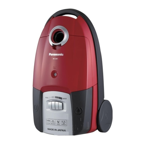
MC-CJ907-W747
Model No.
MC-CJ907-W149
MC-CJ907-W147
MC-CJ907-R747
MC-CJ907-R149
MC-CJ907-R147
MC-CJ907-K747
MC-CJ907-K149
MC-CJ907-K147
Product Color : (W) White
(R) Red
(K) Black
Destination :
1.Saudi Arabia, Kuwait --- MC-CJ907-W747
2.Iran
3.UAE
© Panasonic Corporation 2010 Unauthorized copy-
ing and distribution is a violation of law.
Order Number VCB1001001CE
Vacuum Cleaner
--- MC-CJ907-R747
--- MC-CJ907-K747
--- MC-CJ907-W149
--- MC-CJ907-R149
--- MC-CJ907-K149
--- MC-CJ907-W147
--- MC-CJ907-R147
--- MC-CJ907-K147
Table of Contents

Related Manuals for Panasonic MC-CJ907-W747


Summary of Contents for Panasonic MC-CJ907-W747
- Page 1 MC-CJ907-R747 MC-CJ907-R149 MC-CJ907-R147 MC-CJ907-K747 MC-CJ907-K149 MC-CJ907-K147 Product Color : (W) White (R) Red (K) Black Destination : 1.Saudi Arabia, Kuwait --- MC-CJ907-W747 --- MC-CJ907-R747 --- MC-CJ907-K747 2.Iran --- MC-CJ907-W149 --- MC-CJ907-R149 --- MC-CJ907-K149 3.UAE --- MC-CJ907-W147 --- MC-CJ907-R147 --- MC-CJ907-K147 ©...
-
Page 2: Table Of Contents
TABLE OF CONTENTS PAGE PAGE 1 Specifications ------------------------------------------------------3 2 Location of Controls and Components--------------------4 3 Troubleshooting Guide------------------------------------------5 4 Disassembly and Assembly Instructions -----------------7 4.1. Removal of Dust Cover -----------------------------------7 4.2. Removal of Dust Bag Holder ----------------------------8 4.3. Removal of Body Cover Unit, Cord Rewind Button, and Switch Pedal --------------------------------8 4.4. -
Page 3: Specifications
1 Specifications Model No. MC-CJ907 Power source 220 V - 240 V ~ 50 /60 Hz Max. input 2000 W Nominal input 1350 - 1600 W Dimensions (WxLxH) 315 mm x 557 mm x 252 mm Net weight 7.0kg Extension Wand Telescopic Crevice nozzle Upholstery nozzle... -
Page 4: Location Of Controls And Components
2 Location of Controls and Components... -
Page 5: Troubleshooting Guide
3 Troubleshooting Guide CONDITION CHECKPOINT FIGURE CHECK METHOD REMEDY The motor doesn’t CORD REEL PAR- • Check the continuity at both • If there is no continuity, replace rotate. TITION UNIT ends of the Plug and both ends the Cord Reel Assy, Body Parti- of the Lead Wire Terminal of the tion Assy, or Cord Reel Partition Cord Reel Partition Unit. - Page 6 CONDITION CHECKPOINT FIGURE CHECK METHOD REMEDY The Cord cannot CORD REEL PAR- • If the Cord cannot be pulled out, • If it is impossible to resolve the be pulled out. TITION UNIT press the Brake Lever and con- problem due to an abnormal firm that the Cord can be condition of the Cord, separate rewound.
-
Page 7: Disassembly And Assembly Instructions
4 Disassembly and Assembly Instructions Important: Always turn the vacuum cleaner’s power off before replacing components. Remove the power cord and plug from the mains. * Attention (1) When disassembling the vacuum cleaner, check the connections and wiring (pulling) of each component, and ensure that everything is restored correctly once repairs are complete. -
Page 8: Removal Of Dust Bag Holder
4.2. Removal of Dust Bag Holder * Don't forget to attach the Spring. 1. Insert a slotted screwdriver into the joint of the Dust Bag Holder in the Lower Body Unit and take out the Dust Bag Holder. * Be careful not to lose the Spring on the back of the Dust Bag Holder. -
Page 9: Removal Of Upper Body Unit And Power Control Switch
4.4. Removal of Upper Body Unit 2. Remove the Body Cover Unit from the two projections of the Upper Body Unit using a slotted screwdriver as shown and Power Control Switch in the figure below. 1. Remove the four screws of the Upper Body Unit. 2. -
Page 10: Removal Of On/Off Switch (With Fuse And Capacitor)
4.5. Removal of ON/OFF Switch 4.6. Motor Assy (with motor sup- (with Fuse and Capacitor) port cover and motor case) 1. Remove the Fuse Unit and the ON/OFF Switch from the 1. Remove the Motor Assy from the Lower Body Unit. Motor Support Cover Unit. -
Page 11: Removal Of Motor Set
4.7. Removal of Motor Set 3. Remove the screws from the Motor Support Rubber and then remove the Motor Support Rubber (two pieces). 1. Remove the Motor Support Cover Unit. 4. Remove the Noise Suppressor Unit. 2. Remove the Motor Set from the Motor Case Unit. 5. -
Page 12: Removal Of Thermo Protector
4.8. Removal of Thermo Protector ※ Use the dedicated tool to crimp the crimp contact. 1. Remove the Thermo Protector. * The Thermo Protector is supplied as an assembly with an ON/OFF Switch Unit (with Thermo Protector and Fuse). Assembling: When replacing the Cord Reel Partition Unit with a new one, connect it using Wire Connector CE-230 and wrap Gasket V (Glass Tape) around it. -
Page 13: Wiring Connection Diagram
5 Wiring Connection Diagram... -
Page 14: Printed Circuit Board
6 Printed Circuit Board... -
Page 15: Exploded View And Replacement Parts List
7 Exploded View and Replacement Parts List 7.1. EXPLODED VIEW (ATTACHMENTS) 7.2. PARTS LIST (ATTACHMENTS) Safety Ref.No Service Parts No. Part Name & Description Q'TY Remarks AMV84P9U0S0J HOSE UNIT (HOSE) AMC24P-0R0V HOSE SUPPORTER AMC92P-GA0V CONNECTION PIPE AMC98P-TB0V CURVED WAND (SUCTION REGULATOR) AMV99P9U000J EXTENSION WAND UNIT (TELESCOPIC WAND) -
Page 16: Exploded View (Body Unit)
7.3. EXPLODED VIEW (BODY UNIT) Saudi Arabia Kuwait, UAE Iran... -
Page 17: Parts List (Body Unit)
7.4. PARTS LIST (BODY UNIT) Safety Ref.No Service Parts No. Part Name & Description Q'TY Remarks AMV83P9U0W0J TOOL STORAGE COVER WHITE AMV83P9U0Q0J TOOL STORAGE COVER AMV83P9U0K0J TOOL STORAGE COVER BRACK AMV59H9U0S0J FRONT MARK PRINT AMV98M9U000J INDICATOR UNIT (DAST INDICATOR) AMV60K9U0W0J DUST COVER WHITE AMV60K9U0Q0J... - Page 18 Safety Ref.No Service Parts No. Part Name & Description Q'TY Remarks AMC10Z-RD0 BODY BAG AMV72Z9U000J CUSHION PLATE A...