Table of Contents
Quick Links
SITRANS
Radar Transmitters
SITRANS LR200 with mA/HART
Operating Instructions
7ML5422 (Polypropylene rod antenna)
7ML5423 (Rod antenna)
7ML5425 (Horn antenna)
05/2019
A5E32337676-AE
Introduction
Safety notes
Description
Installing/mounting
Connecting
Operating
Parameter reference
Service and maintenance
Diagnosing and
troubleshooting
Technical data
Dimension drawing
Antenna options
Technical reference
HART communication
Certificates and support
LCD menu structure
Abbreviations
1
2
3
4
5
6
7
8
9
10
11
A
B
C
D
E
F
Table of Contents
Troubleshooting

Related Manuals for Siemens SITRANS LR200 7ML5422


Summary of Contents for Siemens SITRANS LR200 7ML5422
- Page 1 Introduction Safety notes Description SITRANS Installing/mounting Radar Transmitters SITRANS LR200 with mA/HART Connecting Operating Operating Instructions Parameter reference Service and maintenance Diagnosing and troubleshooting Technical data Dimension drawing Antenna options Technical reference HART communication 7ML5422 (Polypropylene rod antenna) 7ML5423 (Rod antenna) Certificates and support 7ML5425 (Horn antenna) LCD menu structure...
- Page 2 Note the following: WARNING Siemens products may only be used for the applications described in the catalog and in the relevant technical documentation. If products and components from other manufacturers are used, these must be recommended or approved by Siemens. Proper transport, storage, installation, assembly, commissioning, operation and maintenance are required to ensure that the products operate safely and without any problems.
-
Page 3: Table Of Contents
Table of contents Introduction .............................. 10 Purpose of this documentation ....................10 Checking the consignment ..................... 10 Security information ........................ 10 Transportation and storage ..................... 11 Notes on warranty ........................11 Safety notes ............................. 12 Preconditions for safe use ...................... 12 Laws and directives ........................ - Page 4 Table of contents Basic safety notes ........................29 Connecting SITRANS LR200 ....................30 5.2.1 Connecting HART ........................32 5.2.2 Typical PLC configuration with HART ..................32 Nameplates for hazardous area installations ................. 33 5.3.1 Intrinsically Safe wiring ......................33 5.3.1.1 Device nameplate (ATEX/IECEX/INMETRO/RCM) ...............
- Page 5 Table of contents Setup (2.) ..........................98 7.2.1 Sensor (2.2.) ........................... 99 7.2.1.1 Units (2.2.1.) ........................... 99 7.2.1.2 Sensor mode (2.2.2.) ......................99 7.2.1.3 Material (2.2.3.) ........................99 7.2.1.4 Damping filter (2.2.4.) ......................100 7.2.1.5 Antenna (2.2.5.) ........................100 7.2.2 Calibration (2.3.) ........................
- Page 6 Table of contents 7.4.2 Remaining device lifetime (4.2.) ................... 121 7.4.2.1 Lifetime expected (4.2.1.) ....................122 7.4.2.2 Time in operation (4.2.2.) ..................... 122 7.4.2.3 Remaining lifetime (4.2.3.) ....................122 7.4.2.4 Reminder activation (4.2.4.) ....................122 7.4.2.5 Reminder 1 (required) (4.2.5.) ..................... 123 7.4.2.6 Reminder 2 (demanded) (4.2.6.) ..................
- Page 7 Table of contents 7.6.2 Local access (6.2.) ........................ 134 7.6.2.1 Write protect (6.2.1.) ......................134 7.6.2.2 Pin to unlock (6.2.2.) ......................135 Language (7.) ........................135 Service and maintenance ........................136 Maintenance and repair ......................136 8.1.1 Maintenance ......................... 136 Cleaning ..........................
- Page 8 Table of contents Raised-face flange dimensions .................... 161 Raised-face flange markings ....................161 A.10 Flat-face flange (constant thickness series) ................ 162 A.11 Flat-face flange dimensions ....................163 A.12 Flat-face markings ....................... 164 A.12.1 Threaded connection markings .................... 164 A.13 Flange mounting instructions ....................165 A.14 Rod assembly ........................
- Page 9 Table of contents B.7.1 Typical connection drawing ....................189 Allowable operating area of SITRANS LR200 ..............190 B.8.1 Loop voltage versus loop resistance ..................190 HART communication ..........................192 SIMATIC PDM ........................192 HART Electronic Device Description (EDD) ................. 192 HART Communicator 375 Menu Structure ................
-
Page 10: Introduction
In order to protect plants, systems, machines and networks against cyber threats, it is necessary to implement – and continuously maintain – a holistic, state-of-the-art industrial security concept. Siemens’ products and solutions only form one element of such a concept. Customer is responsible to prevent unauthorized access to its plants, systems, machines and networks. -
Page 11: Transportation And Storage
The sales contract contains all obligations on the part of Siemens as well as the complete and solely applicable warranty conditions. Any statements regarding device versions described in the manual do not create new warranties or modify the existing warranty. -
Page 12: Safety Notes
Safety notes Preconditions for safe use This device left the factory in good working condition. In order to maintain this status and to ensure safe operation of the device, observe these instructions and all the specifications relevant to safety. Observe the information and symbols on the device. Do not remove any information or symbols from the device. -
Page 13: Fcc Conformity
Safety notes 2.2 Laws and directives 2.2.1 FCC Conformity US Installations only: Federal Communications Commission (FCC) rules Note • This equipment has been tested and found to comply with the limits for a Class A digital device, pursuant to Part 15 of the FCC Rules. These limits are designed to provide reasonable protection against harmful interference when the equipment is operated in a commercial environment. -
Page 14: Radio Equipment Directive (Red) Compliance (Europe)
2.2.3 Radio Equipment Directive (RED) compliance (Europe) Hereby, Siemens declares that the SITRANS LR200 is in compliance with the essential requirements and other relevant provisions of Directive 2014/53/EU. The LR200 complies with EN 302 372 for use in closed storage vessels, when installed according to the installation requirements of EN 302 372, and may be used in all EU countries. -
Page 15: Requirements For Special Applications
Due to the large number of possible applications, each detail of the described device versions for each possible scenario during commissioning, operation, maintenance or operation in systems cannot be considered in the instructions. If you need additional information not covered by these instructions, contact your local Siemens office or company representative. Note... -
Page 16: Lithium Batteries
Safety notes 2.4 Lithium batteries WARNING Loss of safety of device with type of protection "Intrinsic safety Ex i" If the device or its components have already been operated in non-intrinsically safe circuits or the electrical specifications have not been observed, the safety of the device is no longer ensured for use in hazardous areas. -
Page 17: Description
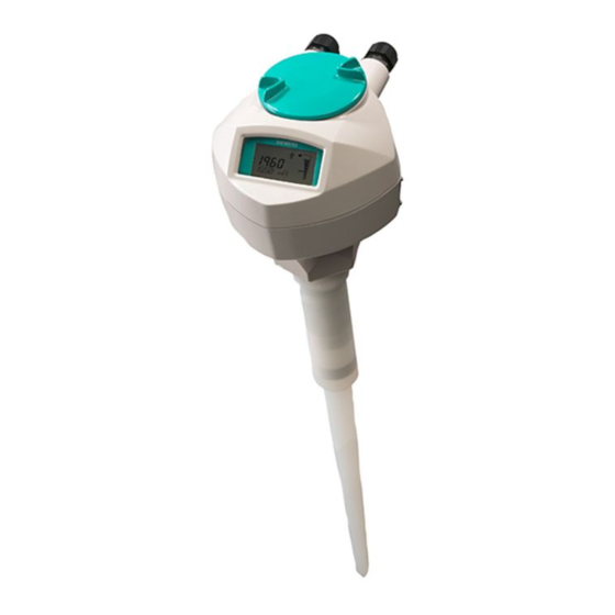
Description SITRANS LR200 Overview SITRANS LR200 is a 2-wire 6 GHz pulse radar level transmitter for continuous monitoring of liquids and slurries in storage vessels including high pressure and high temperature, to a range of 20 meters (66 feet). The instrument consists of an electronic component coupled to an antenna and either a threaded or flange type process connection. -
Page 18: Programming
SITRANS LR200 is very easy to install and configure via a graphical Human Machine Interface (HMI). You can modify the built in parameters either locally via the Siemens infrared handheld programmer, or from a remote location using one of the following options: ●... -
Page 19: Installing/Mounting
Installing/mounting Basic safety notes WARNING Unsuitable connecting parts Risk of injury or poisoning. In case of improper mounting, hot, toxic, and corrosive process media could be released at the connections. • Ensure that connecting parts (such as flange gaskets and bolts) are suitable for connection and process media. - Page 20 • Prevent severe external stresses and loads from acting on the device. Note Material compatibility Siemens can provide you with support concerning selection of sensor components wetted by process media. However, you are responsible for the selection of components. Siemens accepts no liability for faults or failures resulting from incompatible materials.
-
Page 21: Mounting
Installing/mounting 4.2 Mounting Mounting NOTICE Incorrect mounting The device can be damaged, destroyed, or its functionality impaired through improper mounting. • Before installing ensure there is no visible damage to the device. • Make sure that process connectors are clean, and suitable gaskets and glands are used. -
Page 22: Nozzle Design
Installing/mounting 4.2 Mounting 4.2.1.1 Nozzle design ● For nozzles 100 mm (4") in length or shorter use the 100 mm (4") shield. ● For nozzles 250 mm (10") in length or shorter use the 250 mm (10") shield. The end of the shield section or end of the horn should protrude a minimum of 10 mm (0.4”) to avoid false echoes being reflected from the nozzle. -
Page 23: Nozzle Location
Installing/mounting 4.2 Mounting 4.2.1.2 Nozzle location Beam angle ● Beam angle is the width of the cone where the energy density is half of the peak energy density. ● The peak energy density is directly in front of and in line with the rod antenna. ●... -
Page 24: Access For Programming
Installing/mounting 4.2 Mounting 4.2.1.3 Access for programming Provide easy access for viewing the display and programming via the handheld programmer. ① Ambient temperature (surrounding enclosure volume) -40 to +80 °C (-40 to +176 °F) ② Device nameplate ③ Process device tag ④... -
Page 25: Orientation In A Vessel With Obstructions
Installing/mounting 4.2 Mounting 4.2.1.4 Orientation in a vessel with obstructions Polarization reference point For best results on a vessel with obstructions, or a stillpipe with openings, orient the front or back of the device toward the obstructions. For an illustration, refer to Mounting on a stillpipe or bypass pipe (Page 25). - Page 26 Installing/mounting 4.2 Mounting Device orientation Bypass installation ① Vent ② Align front or back of device with vents ③ Optimum diameter 80 mm (3") Stillpipe installation ① Slots ② Align front or back of device with stillpipe slots SITRANS LR200 with mA/HART Operating Instructions, 05/2019, A5E32337676-AE...
-
Page 27: Installation
4.3 Installation Installation Siemens Level Transmitters with flanged, threaded, or sanitary clamp type process mounts have no pressure-bearing housing of their own and, therefore, do not come under the Pressure Equipment Directive as pressure or safety accessories, (see EU Commission Guideline 1/8). -
Page 28: Disassembly
Installing/mounting 4.4 Disassembly 3. If you want to rotate the enclosure, use a 2 mm Allen key to loosen the set screws that secure the locking ring 4. Once the enclosure is in a suitable position, tighten the set screws. ①... -
Page 29: Connecting
Connecting Basic safety notes WARNING Unsuitable cables, cable glands and/or plugs Risk of explosion in hazardous areas. • Use only cable glands/plugs that comply with the requirements for the relevant type of protection. • Close unused cable inlets for the electrical connections. •... -
Page 30: Connecting Sitrans Lr200
WARNING Unprotected cable ends Risk of explosion through unprotected cable ends in hazardous areas. • Protect unused cable ends in accordance with IEC/EN 60079-14. WARNING Improper laying of shielded cables Risk of explosion through compensating currents between hazardous area and the non-hazardous area. - Page 31 ① Use a 2 mm Allen key loosen the lid-lock ④ Locking ring set screw. ② ⑤ Plug Threaded connection ③ Optional cable gland (or NPT cable entry 1) 2) If you want to rotate the enclosure, use the 2 mm Allen key to loosen the locking ring. 1.
-
Page 32: Connecting Hart
5.2.1 Connecting HART Note • Depending on the system design, the power supply may be separate from the PLC, or integral to it. • HART resistance (total of loop resistance, that is, cable resistance plus 250 Ohm [resistor]) must be limited according to the allowable operating area as shown in either diagram under Loop voltage versus loop resistance (Page 190). -
Page 33: Nameplates For Hazardous Area Installations
① The ATEX certificate can be downloaded from the product page of our website at www.siemens.com/LR200 (www.siemens.com/LR200). Go to Support > Approvals / Certifi- cates. The IECEx certificate listed on the nameplate can be viewed on the IECEx website. Go to: http://iecex.iec.ch (http://iecex.iec.ch) and click on Ex Equipment Certificates of Conformity... -
Page 34: Device Nameplate (Fm/Csa)
FM Intrinsically Safe connection drawing number A5E01003040 and CSA Intrinsically Safe connection drawing number A5E01003039 can be downloaded from the product page of our website at: www.siemens.com/LR200 (www.siemens.com/LR200). Go to Support > Installation Drawings > Level Measurement > Continuous - Radar. - Page 35 6. Installation and inspection of this equipment shall be carried out by suitably trained personnel in accordance with the applicable code of practice (EN 60079-14 and EN 60079-17 in Europe). 7. The equipment contains no user-replaceable parts and is not intended to be repaired by the user.
-
Page 36: Operating
Operating Basic safety notes DANGER Toxic gases and liquids Danger of poisoning when venting the device: if toxic process media are measured, toxic gases and liquids can be released. • Before venting ensure that there are no toxic gases or liquids in the device, or take the appropriate safety measures. -
Page 37: Activating Sitrans Lr200
6.2.1.1 Activating SITRANS LR200 Power up the instrument. SITRANS LR200 automatically starts up in Measurement mode. A transition screen showing the current firmware revision and an incrementing line of stars is displayed while the first measurement is being processed. Press Mode to toggle between Measurement and Program Mode. - Page 38 PROGRAM mode display Navigation view ① ④ Item band Current item number ② ⑤ Menu bar Current item ③ Current menu ● A visible menu bar indicates the menu list is too long to display all items. ● A band halfway down the menu bar indicates the current item is halfway down the list. ●...
- Page 39 Key functions in measurement mode Function Result Updates the loop current New value is shown in secondary region of local display. Updates internal enclosure temperature reading Updates echo confidence value New value is shown in secondary region of local display. Updates distance measure- ment Mode opens PROGRAM mode...
- Page 40 Parameter menus Note For the complete list of parameters with instructions, see Parameter reference (Page 97). Parameters are identified by name and organized into function groups. See LCD menu structure (Page 197). 1. QUICK START 2. SETUP 2.1. DEVICE .... 2.7.
- Page 41 2. Navigating: key functions in Navigation mode Note • In Navigation mode ARROW keys move to the next menu item in the direction of the arrow. • For Quick Access to parameters via the handheld programmer, press Home , then enter the menu number, for example: 2.7.1.
- Page 42 4. Changing a numeric value ● Navigate to the desired parameter. ● Press RIGHT arrow to open parameter view. The current value is displayed. ● Press RIGHT arrow again to open Edit mode. The current value is highlighted. ● Key in a new value. ●...
-
Page 43: Quick Start Wizard Via The Handheld Programmer
Key functions in edit mode Name Function UP or DOWN Selecting options Scrolls to item. arrow Numeric editing Increments or decrements digits • Toggles plus and minus sign • RIGHT arrow Selecting options Accepts the data (writes the parameter) • Changes from Edit to Navigation mode •... - Page 44 Language Selects the language to be used on the LCD and takes effect immediately. Options English, Deutsch, Français, Español Material Selects the appropriate echo processing algorithms for the material. See Position detect (2.8.4.2.) (Page 112) for more detail. Options LIQUID LIQUID LOW DK (low dielectric liquid –...
-
Page 45: Auto False Echo Suppression
Operation Description NO SERVICE Measurement and associated loop current are not updated, and the device defaults to Fail-safe mode. LEVEL Distance to material surface referenced from Low Calibration Point SPACE Distance to material surface referenced from High Calibration Point DISTANCE Distance to material surface referenced from Sensor reference point The point from which High and Low Calibration points are referenced: see Uni-construction polypropylene rod antenna (Page 152) and Dimension drawing (Page 152). -
Page 46: Requesting An Echo Profile
6.2.1.4 Requesting an Echo Profile ● In PROGRAM mode, navigate to: Level Meter >Diagnostics (3.) (Page 119) > Echo profile (3.1.) (Page 119) ● Press RIGHT arrow to request a profile. ① Confidence ⑦ Zoom ② ⑧ Distance from Low Calibration Point to vertical cross- Measure hair ③... -
Page 47: Application Examples
6.2.2 Application examples Note In the applications illustrated below, values are for example purposes only. You can use these examples as setup references. Enter the values in the parameter tables to select the corresponding functions. Configure the basic settings using the Quick Start wizard parameters. (These parameters are inter-related, and changes take effect only after you select YES to apply changes in the last step.) In each example, after performing a Quick Start, navigate to the other required parameters... - Page 48 Quick Start Parameter Setting Description Vessel STEEL Selects vessel construction material. Response Rate SLOW Resets fill rate and empty rate to 0.1 m/minute. Units Sensor measurement units. Operation LEVEL Material level referenced from low calibration point Low Calibration Point 15.5 Process empty level.
-
Page 49: Horizontal Vessel With Volume Measurement
Parameter type Parameter no./name Options/values Function Quick start wizard Material (1.2.) LIQUID parameters Response Rate (1.3.) Medium =1 m/minute Units (1.4.) meters Operating Mode (1.5.) LEVEL Level Low Calibration Point (1.6.) 5 m (16.5 ft) High Calibration Point (1.7.) 0.5 m (1.64 ft) Apply? [Apply changes (1.8.)] YES Transfers Quick Start set- tings to device. - Page 50 ① ⑥ Sensor reference point A=0.8 m ② ⑦ 0.5 m L=6 m ③ ⑧ High calibration point Volume reading ④ ⑨ 3.5 m 100%=8000 L ⑤ Low calibration point Parameter Parameter no./name Options/values Function type Quick Start Material (1.2.) LIQUID Wizard pa- Response Rate (1.3.)
-
Page 51: Sliding Waveguide On Anaerobic Digesters
6.2.2.3 Sliding waveguide on anaerobic digesters Note • Minimum distance from the flange face to the target is limited by Far range (2.8.2.) (Page 111). • We recommend adjusting Auto False Echo Suppression parameters with an empty or almost empty vessel. This application is to obtain a level measurement and corresponding 4 to 20 mA output proportional to the sludge level on a digester. -
Page 52: Application With Stillpipe
Parameter type Parameter name (number) Value Function Apply? (Apply changes) (1.8.) Independent Timer (2.5.2.) (Page 103) 2 minutes parameters Material Level (2.5.1.) (Page 103) Auto False Echo Suppression Range [Distance Sets length of learned (2.8.7.2.) (Page 117) nus 0.42 m] TVT curve to use Auto False Echo Suppression... -
Page 53: Propagation Factor/Stillpipe Diameter
① ⑤ Sensor reference point Low calibration point ② ⑥ 0.5 m ③ ⑦ Vent hole High calibration point ④ 50 mm I.D. Parameter Parameter no./name Options/Values Function type Quick start Material (1.2.) LIQUID LOW wizard Response Rate (1.3.) Medium =1 m/minute Units (1.4.) meters Operating Mode (1.5.) -
Page 54: Remote Operation
SIMATIC PDM is a software package used to commission and maintain SITRANS LR200 and other process devices. Please consult the operating instructions or online help for details on using SIMATIC PDM. You can find more information at www.siemens.com/simatic-pdm (www.siemens.com/simatic-pdm). 6.3.1.1... -
Page 55: Initial Setup
® Windows is a registered trademark of the Microsoft Corporation Updating the Electronic Device Description (EDD) You can locate the EDD in Device Catalog, under Sensors/Level/Echo/Siemens Milltronics/SITRANS LR200. Check the product page of our website at: www.siemens.com/LR200 (www.siemens.com/LR200) to make sure you have the latest version of SIMATIC PDM, the most recent Service Pack (SP) and the most recent hot fix (HF). -
Page 56: Quick Start Wizard Via Simatic Pdm
To install a new EDD: 1. Download the EDD from the product page of our website at www.siemens.com/LR200 (www.siemens.com/LR200) and save the files to your computer. 2. Extract the zipped file to an easily accessed location. 3. Launch SIMATIC PDM – Manage Device Catalog, browse to the unzipped EDD file and select it. - Page 57 Quick Start Note • The Quick Start Wizard settings are inter-related and changes apply only after you click on FINISH AND DOWNLOAD at the end of step 5 to save settings offline and transfer them to the device. • Do not use the Quick Start Wizard to modify individual parameters. For quick access to echo profile parameters see Echo Setup (Page 69), or see Parameter Reference (Page 97) for a complete list.
- Page 58 Step 2 - Application Select the application type (level or volume) and the material , then click on NEXT. See Application with Stillpipe (Page 52) for a Low Dielectric Liquid application. Step 3 - Vessel Shape The vessel shapes shown are predefined. To describe a more complex shape see Using Linearization via the Quick Start Wizard (Page 61).
- Page 59 Step 4 - Range Set the parameters, and click on NEXT. SITRANS LR200 with mA/HART Operating Instructions, 05/2019, A5E32337676-AE...
- Page 60 Step 5 - Summary Check parameter settings, and click on BACK to return and revise values, FINISH to save settings offline, or FINISH AND DOWNLOAD to save settings offline and transfer them to the device. The message Quick Start was successful will appear. Click on OK. Linearization You can use the linearization feature to define a more complex vessel shape and enter up to 32 level breakpoints where the corresponding volume is known.
- Page 61 Using Linearization via the Quick Start Wizard Open the menu Device - Wizard - Quick Start: In Step 1 - Identification, click on Read Data from Device, select language, and click on Next. In Step 2 – Application, select a volume application, for example Volume in a vessel, and click on Next.
- Page 62 ● Enter the desired level and associated volume values , and click on OK. Note The Reset button resets values to the values in the offline table. ① Breakpoints 1-8 ● In the Step 4 window, click on NEXT. In Step 5 – Summary, check parameter values. Click on BACK to return and revise values, FINISH to save settings offline, or FINISH AND DOWNLOAD to save settings offline and transfer them to the device.
-
Page 63: Changing Parameter Settings Using Simatic Pdm
Configuring a stillpipe application ● Launch the Quick Start wizard and follow steps 1 to 2. ● In step 2, select Application Type – Level in a vessel with stillpipe, Material – Liquid Low dK, and set the stillpipe diameter as desired. ●... -
Page 64: Parameters Accessed Via Pull-Down Menus
① Value fields 6.3.1.5 Parameters accessed via pull-down menus Click on Device or View to open the associated pull-down menus. ① Pull-down menus Pull-down menus Device menus View menus Communication path Process Variables (Page 73) Device Status (Page 75) Download to device Upload to PC/PG Update Di- Toolbar agnostic Status Status bar... - Page 65 Echo profile utilities Open the menu Device – Echo Profile Utilities and click on the appropriate tab for easy access to: ● Echo profile (Page 65) ● View Saved Echo Profiles (Page 65) ● TVT Shaper (Page 66) ● Auto False Echo Suppression (Page 67) ●...
- Page 66 Echo profile data logging You can store up to 60 profiles at a selected interval (maximum 60 minutes). Inside Echo Profile Utilities, in the Echo Profile Time Based Storage window: 1. Enter the desired interval between stored profiles. 2. Enter the desired number of profiles to be stored (maximum 60). 3.
- Page 67 Auto false echo suppression Note • Ensure material level is below all known obstructions when using Auto False Echo Suppression to learn the echo profile. An empty or almost empty vessel is recommended. • Note the distance to material level when learning the echo profile, and set Auto False Echo Suppression Range to a shorter distance to avoid the material echo being screened out.
- Page 68 4. Make sure Auto False Echo Suppression Range is On. 5. Enter the value for Auto False Echo Suppression Range. 6. Click Learn. The message appears: 'This will learn a new echo profile. Once done it cannot be undone'. Click OK. 7.
- Page 69 After Auto False Echo Suppression ① ④ False echo Material level ② ⑤ Learned TVT Default TVT ③ ⑥ Auto False Echo Suppression Range Echo marker Echo Setup Provides quick access to echo profile parameters: ① ⑤ Algorithm CLEF Range ②...
- Page 70 Maintenance You can set schedules and reminders for: ● device maintenance based on its projected lifetime ● sensor maintenance based on its projected lifetime ● service ● calibration To set Device/Sensor Maintenance schedules: 1. Open the menu Device – Maintenance, and click on the Remaining Device/Sensor Lifetime tab.
- Page 71 Select analog output Allows you to set the mA Output to report Level, Distance, Space, or Volume. See Current Output Function (2.6.1.) for an illustration. If a volume application is selected, mA Output is automatically set to Volume. See Analog Output (Page 178) for more details.
- Page 72 Master Reset Factory Defaults Use Factory Defaults to reset all user parameters to the default settings, with certain exceptions. The list of exceptions includes, but is not limited to: ● Tag ● Message ● Description ● Installation Data ● Device Address ●...
- Page 73 Diagnostics You can monitor level/volume trends, electronics temperature, and device status. Process variables To compare outputs in real time open the menu View – Process Variables and click on Overview to see reading (level, space, distance, volume); analog output; device status; and current electronics temperature.
- Page 74 Trend Open the menu View – Process Variables and click on Trend. Four trend lines can be monitored (distinguished by color in SIMATIC PDM): ① Space ② Distance ③ Level ④ Volume SITRANS LR200 with mA/HART Operating Instructions, 05/2019, A5E32337676-AE...
- Page 75 Device Status Open the menu View – Device Status to view Diagnostics, Device Status, Hardware/ Firmware (HW/FW) Status, and Maintenance status. ① Update diagnostics In the Diagnostics window, click on Update diagnostics to update diagnostic information and refresh linked icons. Update Open the menu View –...
-
Page 76: Operating Via Ams Device Manager
Security A password option protects security and communication control parameters from modification by a maintenance user. When you open a project the User dialog window provides two options: maintenance or specialist. If a password has been set it will not be possible to open the project as a specialist without it. - Page 77 You can locate the EDD in Device Catalog, under Sensors/Level/Echo/Siemens Milltronics/SITRANS LR200. Check the product page of our LR200 (www.siemens.com/LR200), under Support > Software Downloads, to make sure you have the latest version of the EDD for AMS Device Manager. If you need to install a new EDD, see Configuring a new device (Page 77) below.
- Page 78 1. Launch AMS Device Manager. (Application Guides for setting up HART devices with AMS Device Manager can be downloaded from our website: www.siemens.com/LR200 (www.siemens.com/LR200) 2. In Device Connection View right-click on the device icon and select Scan Device to upload parameters from the device.
- Page 79 Pull-down menu access ① Action menu items A pull-down menu under Actions gives alternative access to several features. Scan Device ● Open the menu Actions - Scan Device. ● Scan Device uploads parameters from the device (synchronizes parameters). Device configuration 1.
- Page 80 Quick Start Wizard via AMS Device Manager Note • The layout of the dialog boxes shown may vary according to the resolution setting for your computer monitor • At each step, you can accept the default values without modification and click on the next step to proceed.
- Page 81 Step 3 - Vessel Shape 1. Click on Step 3. 2. Select a predefined vessel shape. (To describe a more complex shape see Linearization below.) 3. Click on Apply. Step 4 - Range 1. Click on Step 4. 2. Change units if desired (in meters by default). 3.
- Page 82 5. In Step 4 – Ranges, enter a value for maximum volume. ① Breakpoints ② Maximum volume 6. Click on the Breakpoints tab and enter values for level and volume for up to 32 breakpoints. 7. Navigate to Configure/Setup > Setup > Linearization and click on Characteristic to preview the characteristic curve of the vessel breakpoints.
- Page 83 Operation Navigate to Configure/Setup > Operation and click on Operation to open the dialog window for access to: General ● Select Analog Output, see Select analog output (Page 71) ● Master Reset, see Master Reset (Page 72) Simulation/Test ● Self Test, see Self Test (Page 71) ●...
- Page 84 Setup Note For more detailed explanations of the parameters listed below see the pages referenced. Sensor Navigate to Configure/Setup > Setup and click on Sensor for access to: General, see Sensor (2.2.) ● Units ● Operating Mode ● Material ● Damping Filter Calibration, see Calibration (2.3.) ●...
- Page 85 Fail-safe, see Fail-safe (2.5.) ● Material level ● Timer ● Level Analog output scale Navigate to Configure/Setup > Setup and click on Analog Output Scaling for access to: ● Current Output Function ● 4 mA Setpoint ● 20 mA Setpoint ●...
- Page 86 Signal processing General Navigate to Configure/Setup > Setup > Signal Processing and click on General for access to: Range, see Signal Processing (2.8.) ● Near Range ● Far Range ● Propagation Factor Echo Select, see Echo Select (2.8.4.) ● Algorithm ●...
- Page 87 Modify the TVT to screen out false echoes [see Auto False Echo Suppression (2.8.7.1.) (Page 115)]. Navigate to Configure/Setup > Setup > Signal Processing and click on TVT. Click on one of the two tabs to access the parameters listed. TVT Setup [see TVT setup (2.8.7.)] ●...
-
Page 88: Maintenance And Diagnostics
Local Display Navigate to Configure/Setup > Setup > Local Display for access to: ● Language ● LCD Fast Mode [see LCD Fast Mode (4.9.)] ● LCD Contrast [see LCD Contrast (4.10.)] 6.3.2.2 Maintenance and diagnostics Navigate to Maintenance and Diagnostics for access to: Remaining Device Lifetime [see Remaining Device Lifetime (4.2.)] ●... -
Page 89: Communication
Electronic Temperature ● Electronic Temperature ● Lowest Value ● Highest Value Wear ● Powered Days ● Poweron Resets See Wear via SIMATIC PDM (Page 72) for more detail. 6.3.2.3 Communication Navigate to Communication to read the following: Tag; Manufacturer’s ID; Device ID; Product ID; Device Revision; EDD Revision; Universal Command 6.3.2.4 Security... -
Page 90: Device Diagnostics
6.3.2.5 Device Diagnostics Click on the Device Diagnostics bar at the bottom of the navigation window, for access to: ● Device Status ● Hardware/Firmware Status Process variables To compare outputs in real time click on Process Variables at the bottom of the navigation window for access to: Process Variables ●... -
Page 91: Password Protection
6.3.2.6 Password Protection An AMS Device Manager administrator can configure the user to require a password. The use of passwords is recommended. A password should be assigned to the ’admin’ username immediately after installing AMS Device Manager. Each user is given an AMS Device Manager username and password and required to enter them when they start AMS Device Manager. -
Page 92: Ams Device Menu
6.3.2.8 AMS device menu Configure/setup Identification Identification Description Message Date Device Manufacturer Product name Order number Final assembly number Hardware revision Firmware revision Loader revision EDD number Wizard Quick start Step 1 (Identification) Step 2 (Application type) Step 3 (Vessel shape) Step 4 (Range) Step 5 (Summary) Operation... - Page 93 Low calibration point High calibration point Sensor offset Rate Response rate Fill rate/minute Fail-safe Timer Material level Level Analog output scaling Analog output scaling mA output function Start of scale Full scale Control range lower limit Control range upper limit Linearization Linearization Vessel shape...
- Page 94 Signal quality Confidence Echo strength Noise average Noise peak TVT setup Auto false echo suppression range Auto false echo suppression Hover level Shaper mode TVT shaper Manual TVT curve Echo profile Local display Maintenance and diagnostics Remaining device lifetime Lifetime expected Remaining Lifetime Time in Operation Activation of Reminders...
-
Page 95: Operating Via Fdt (Field Device Tool)
Activation of Reminders Reminder 1 before Calibration (Required) Reminder 2 before Calibration (Demanded) Electronic Temperature Electronic Temperature Lowest Value Highest Value Wear Powered days Poweron Resets Communication Security Remote access Write protect Access control Local access Local write protected PIN to unlock 6.3.3 Operating via FDT (Field Device Tool) FDT is a standard used in several software packages designed to commission and maintain... -
Page 96: Sitrans Dtm
6.3.3.2 SITRANS DTM ● SITRANS DTM is an EDDL interpreter developed by Siemens to interpret the EDD for that device. ● To use SITRANS DTM to connect to a device, you must first install SITRANS DTM on your system and then install the device EDD written for SITRANS DTM. -
Page 97: Parameter Reference
Parameter reference Note • Parameter names and menu structure are almost identical for SIMATIC PDM and the local display interface (LDI). • To enter Program mode using the device buttons, press . Press to return to Measurement mode. • Mode toggles between PROGRAM and Measurement Modes via the handheld programmer. -
Page 98: Quick Start (1.)
Quick start (1.) The Quick Start wizard provides an easy step-by-step procedure to configure the device for a simple application. From measurement screen, press RIGHT arrow twice to open the Quick Start Wizard menu. Select a wizard, press RIGHT arrow to open the first step, and follow the instructions. -
Page 99: Sensor (2.2.)
7.2.1 Sensor (2.2.) 7.2.1.1 Units (2.2.1.) Description sensor measurement units Options m, cm, mm, ft, in Factory setting 7.2.1.2 Sensor mode (2.2.2.) ① ⑤ Sensor value Low calibration point ② ⑥ Space Far range ③ ⑦ Distance Level ④ High calibration point Mode Description Reference point... -
Page 100: Damping Filter (2.2.4.)
7.2.1.4 Damping filter (2.2.4.) Description The time constant for the damping filter. The damping filter smooths out the response to a sudden change in level. This is an exponential filter and the engi- neering unit is always in seconds. For more detail, refer to Damping (Page 178). Values Range: 0 to 100.000 s Factory setting... -
Page 101: High Calibration Point (2.3.2.)
7.2.2.2 High calibration point (2.3.2.) Description Distance from sensor reference point to High Calibration Point. Units are de- fined in Units (2.2.1.). Values 0 to 20 m Factory setting 0.00 m Related Units (2.2.1.) (Page 99) parameters Near range (2.8.1.) (Page 110) The value produced by the echo processing which represents the distance from sensor reference point to the target. -
Page 102: Fill Rate/Min (2.4.2.)
7.2.3.2 Fill rate/min (2.4.2.) Fill rate defines the maximum rate at which the reported sensor value is allowed to increase. Allows you to adjust the device's response to increases in the actual material level. Fill rate is automatically updated whenever Response rate (2.4.1.) (Page 101) is altered. Note Enter a value slightly greater than the maximum vessel-filling rate, in units per minute. -
Page 103: Fail-Safe (2.5.)
7.2.4 Fail-safe (2.5.) 7.2.4.1 Material level (2.5.1.) Material Level defines the mA output to use when the Fail-safe Timer expires. STANDARD DEVICE Options 20.5 mA (max. mA Limit) 3.8 mA (min. mA Limit) HOLD (factory setting) Last valid reading (default 22.6 mA) VALUE User-selected value (defined in LEVEL (2.5.3.) NAMUR NE 43-COMPLIANT DEVICE... -
Page 104: Level (2.5.3.)
7.2.4.3 Level (2.5.3.) Note • The default setting depends whether your device is a standard or NAMUR NE 43- compliant device. • Material Level (2.5.1.) must be set to VALUE to enable the Level value to be reported. Allows the user to define the mA value to be reported when the Fail-safe timer expires. Device type STANDARD NAMUR NE43-COMPLIANT... -
Page 105: Start Of Scale (4 Ma Setpoint) (2.6.2.)
Notes: ● Level, space, and distance, have different reference points. ● Sensor Mode resets Current Output Function to the same setting. To select a different option, do so after Sensor Mode has been set. ● Use caution when changing Current Output Function while the device is connected to a HART network. -
Page 106: Control Range; Lower Limit (Min Ma Limit) (2.6.4.)
7.2.5.4 Control range; lower limit (min mA limit) (2.6.4.) Description Prevents the mA output from dropping below this minimum level for a measure- ment value. This does not restrict the Fail-safe or Manual settings. Values Range: 3.8 to 20.5 (mA) Factory setting 3.80 (mA) 7.2.5.5... -
Page 107: Vessel Shapes (2.7.1.1.)
7.2.6.2 Vessel shapes (2.7.1.1.) Defines the vessel shape and allows the LR200 to calculate volume instead of level. If None is selected, no volume conversion is performed. Select the vessel shape matching the monitored vessel or reservoir. Vessel shape LCD Display/ Also required description None... -
Page 108: Maximum Volume (2.7.1.2.)
Vessel shape LCD Display/ Also required description FLAT SLOPED BOTTOM maximum volume, dimension A PARABOLIC ENDS maximum volume, dimension A, Parabolic end horizontal cylinder dimension L LINEAR TABLE maximum volume, tables 1-32 Linearization table (lev- level and volume breakpoints el/volume/breakpoints) Linearization Table must be selected in order for level/volume values to be transferred. -
Page 109: Dimension L (2.7.1.4.)
7.2.6.5 Dimension L (2.7.1.4.) Description Length of the cylindrical section of a horizontal parabolic end vessel. For an illustration, refer to Vessel shapes (2.7.1.1.) (Page 107). Values Range: 0.0000 to 999999 mm Factory setting Related UNITS (1.4.) parameters Vessel shapes (2.7.1.1.) (Page 107) 7.2.6.6 Table 1-8 (2.7.2.) Description... -
Page 110: Signal Processing (2.8.)
Level 1 (2.7.2.1.) 1. Press RIGHT arrow to open Edit mode 2. Enter level value and press RIGHT arrow to accept it. 3. Press down arrow to move to corresponding volume breakpoint. Volume (2.7.2.2.) 1. Press RIGHT arrow to open Edit mode 2. -
Page 111: Far Range (2.8.2.)
7.2.7.2 Far range (2.8.2.) Description Allows the material level to drop below Low Calibration Point without generating a Loss of Echo (LOE) state. Use this feature if the measured surface can drop below the Low Cal. Point in normal operation. For an illustration, refer to Sensor mode (2.2.2.) (Page 99). - Page 112 Position detect (2.8.4.2.) Description Defines where on the echo the distance measurement is determined. Refer to "Position detect" under Echo Selection (Page 172) for more detail. Options Center Hybrid (center and CLEF) CLEF (Constrained Leading Edge Fit) Factory setting Hybrid (center and CLEF) Related CLEF range (2.8.4.4.) (Page 112) parameters...
-
Page 113: Sampling (2.8.5.)
Note CLEF Range is referenced from Low Calibration Point (process empty level). ① CLEF range ② Sensor reference point ③ Low calibration point (process empty level) In applications with low dK materials, we recommend setting CLEF Range parameter to 0.5 m (1.64 ft) and Position detect parameter to Hybrid. -
Page 114: Echo Quality (2.8.6.)
Up sampling (2.8.5.2.) Description Specifies the number of consecutive echoes that must appear above the echo currently selected, before the measurement is accepted as valid. Values Range: 1 to 50 Factory setting Down sampling (2.8.5.3.) Description Specifies the number of consecutive echoes that must appear below the echo currently selected, before the measurement is accepted as valid. -
Page 115: Tvt Setup (2.8.7.)
7.2.7.7 TVT setup (2.8.7.) Auto false echo suppression (2.8.7.1.) Auto false echo suppression is used together with Auto false echo suppression range (2.8.7.2.) (Page 117) to screen out false echoes in a vessel with known obstructions. A ’learned TVT’ (time varying threshold) replaces the default TVT over a specified range. For a more detailed explanation, refer to Auto False Echo Suppression (Page 176). - Page 116 After Auto False Echo Suppression ① Learned TVT ② Default TVT ③ Material level ④ Echo marker ⑤ Auto False Echo Suppression Range ⑥ False echo To set Auto False Echo Suppression via SIMATIC PDM: Open the menu Device – Echo Profile Utilities and click on the tab Auto False Echo Suppression.
-
Page 117: Tvt Shaper (2.8.8.)
Auto false echo suppression range (2.8.7.2.) Description Specifies the range within which Learned TVT is used. For more detail, refer to Auto false echo suppression (2.8.7.1.) (Page 115). Values Range: 0.00 to 20.00 m Factory setting 1.00 m Related Units (2.2.1.) (Page 99) parameters 1. - Page 118 Adjusts the TVT (Time Varying Threshold) at a specified range (breakpoint on the TVT). This allows you to reshape the TVT to avoid unwanted echoes. There are 40 breakpoints arranged in 5 groups. (We recommend using SIMATIC PDM to access this feature.) To use TVT Shaper via SIMATIC PDM: ●...
-
Page 119: Measured Values (2.8.9.)
7.2.7.9 Measured values (2.8.9.) Read only. Allows you to view measured values for diagnostic purposes. In SIMATIC PDM, open the menu View - Process Variables. LEVEL MEASUREMENT (2.8.9.1.) The value for level SPACE MEASUREMENT (2.8.9.2.) The value for space DISTANCE MEASUREMENT (2.8.9.3.) The value for distance VOLUME MEASUREMENT (2.8.9.4.) The value for volume... -
Page 120: Electronics Temperature (3.2.)
7.3.2 Electronics temperature (3.2.) 7.3.2.1 Current internal temperature (3.2.1.) Read only. Displays (in degrees C) the current temperature on the circuit board recorded by the internal electronics. To access via SIMATIC PDM: Open the menu View – Process Variables and check the field Electronics Temperature. 7.3.2.2 Highest value (3.2.2.) Read only. -
Page 121: Remaining Device Lifetime (4.2.)
7.4.2 Remaining device lifetime (4.2.) Note • Four sets of parameters allow you to monitor the Device/Sensor Lifetimes and set up Maintenance/Service schedules, based on operating hours instead of a calendar-based schedule, see Remaining sensor lifetime (4.3.) (Page 124), Service schedule (4.4.) (Page 126), and Calibration schedule (4.5.) (Page 129). -
Page 122: Lifetime Expected (4.2.1.)
7.4.2.1 Lifetime expected (4.2.1.) Note The device always operates in years. Changing the units affects only the parameter view of the Remaining Device Lifetime parameters in SIMATIC PDM. Factory setting: 10.00 years Setting range: 0 to 20 years Purpose: Allows you to override the factory default. Description: Units: hours, days, years, are selectable only via SIMATIC PDM. -
Page 123: Reminder 1 (Required) (4.2.5.)
7.4.2.5 Reminder 1 (required) (4.2.5.) Factory setting: 0.164 years Setting range: 0 to 20 years Purpose: If Remaining lifetime (4.2.3.) (Page 122) is equal to or less than this value, the device generates a Maintenance Required reminder. Description: 1. Modify values as required. 2. -
Page 124: Remaining Sensor Lifetime (4.3.)
7.4.3 Remaining sensor lifetime (4.3.) Note • Four sets of parameters allow you to monitor the Device/Sensor Lifetimes and set up Maintenance/Service schedules, based on operating hours instead of a calendar-based schedule, see Remaining device lifetime (4.2.) (Page 121), Service schedule (4.4.) (Page 126), and Calibration schedule (4.5.) (Page 129). -
Page 125: Remaining Lifetime (4.3.3.)
7.4.3.3 Remaining lifetime (4.3.3.) Read only. Lifetime expected (4.3.1.) (Page 124) less Time in operation (4.3.2.) (Page 124). 7.4.3.4 Reminder activation (4.3.4.) Factory setting: Setting range: Reminder 1 (Maintenance Required), Reminder 2 (Maintenance Demand- ed), Reminders 1 and 2, OFF Purpose: Allows you to enable a maintenance reminder. -
Page 126: Acknowledge (4.3.9.)
7.4.3.9 Acknowledge (4.3.9.) Purpose: Acknowledges the current maintenance reminder. Description: To acknowledge a reminder via SIMATIC PDM: Open the menu Diagnostics > Device Diagnostics and click on the tab • Maintenance. In the Calibration Schedule section, click on Acknowledge Warnings. •... -
Page 127: Service Interval (4.4.1.)
7.4.4.1 Service interval (4.4.1.) Note The device always operates in years. Changing the units affects only the parameter view of the Remaining Sensor Lifetime parameters in SIMATIC PDM. Factory setting: 1.0 year Setting range: 0 to 20 years Purpose: User-configurable recommended time between product inspections. Description: Units: hours, days, years, are selectable only via SIMATIC PDM. -
Page 128: Reminder 1 (Required) (4.4.5.)
7.4.4.5 Reminder 1 (required) (4.4.5.) Factory setting: 0.164 years Setting range: 0 to 20 years Purpose: If Time until next service (4.4.3.) (Page 127) is equal to or less than this value, the device generates a Maintenance Required reminder. Description: 1. -
Page 129: Calibration Schedule (4.5.)
7.4.5 Calibration schedule (4.5.) Note • Four sets of parameters allow you to monitor the Device/Sensor Lifetimes and set up Maintenance/Service schedules, based on operating hours instead of a calendar-based schedule, see also Remaining device lifetime (4.2.) (Page 121), Remaining sensor lifetime (4.3.) (Page 124), and Service schedule (4.4.) (Page 126). -
Page 130: Time Since Last Calibration (4.5.2.)
7.4.5.2 Time since last calibration (4.5.2.) Time elapsed since last calibration. Can be reset to zero after performing a calibration. Can be reset locally by entering 0 in this parameter. To reset to zero: ● In SIMATIC PDM, open the menu Device – Maintenance, click on the Calibration Schedule tab, and click on Calibration Performed to restart the timer and clear any fault messages. -
Page 131: Reminder 2 (Demanded) 4.5.6.)
7.4.5.6 Reminder 2 (demanded) 4.5.6.) Factory setting: 0.019 years Setting range: 0 to 20 years Purpose: If Time until next calibration (4.5.3.) (Page 130) is equal to or less than this value, the device generates a Maintenance Demanded reminder. Description: 1. -
Page 132: Power-On Resets (4.8.)
7.4.8 Power-on resets (4.8.) The number of power cycles that have occurred since manufacture. In SIMATIC PDM, open the menu View – Wear. 7.4.9 LCD fast mode (4.9.) Description Enables a faster rate of measurement from the device by disabling most of the display area. -
Page 133: Memory Test (4.11)
7.4.11 Memory test (4.11) Description Allows verification of the RAM, EEPROM, and flash memory of the device LCD display IDLE No test in progress BUSY Test in progress PASS Memory test successful FAIL Test failed Err1 Test returned unexpected results P Oxcafe Test passed with result data F Oxcafe... -
Page 134: Security (6.)
Security (6.) 7.6.1 Remote access (6.1.) 7.6.1.1 Access control (6.1.1.) Description Enables /disables the read/write access to parameters via remote communica- tions. Options Read only No changes are permitted via remote communications. Read Write Changes are permitted. Restricted Sets the status to Read only, with the potential for another HART device to change this parameter only, via remote communications. -
Page 135: Pin To Unlock (6.2.2.)
7.6.2.2 Pin to unlock (6.2.2.) Description Stores the value to be entered in Write Protect (6.2.1.) (Page 134) to unlock programming. If Write Protect (6.2.1.) (Page 134) is set to a different value, PIN to Unlock (6.2.2.) does not display the Unlock value. Valid only for operation via the handheld programmer. -
Page 136: Service And Maintenance
WARNING Impermissible repair of the device • Repair must be carried out by Siemens authorized personnel only. Cleaning Cleaning the enclosure ● Clean the outside of the enclosure with the inscriptions and the display window using a cloth moistened with water or a mild detergent. -
Page 137: Return Procedure
– Number of returned devices/replacement parts – Reason for returning the item(s) ● Decontamination declaration (http://www.siemens.com/sc/declarationofdecontamination) With this declaration you warrant "that the device/replacement part has been carefully cleaned and is free of residues. The device/replacement part does not pose a hazard for humans and the environment."... -
Page 138: Disposal
Further information about devices containing batteries can be found at: Information about battery/product return (WEEE) (https://support.industry.siemens.com/cs/document/109479891/) Replacing the antenna ● When a new antenna is installed the propagation factor will not change. ● After replacing the antenna check the material level reported by the device against the actual material level, and if necessary use Sensor Offset (2.3.3.) (Page 101) to... -
Page 139: Diagnosing And Troubleshooting
Try pressing Mode to put the device into PROGRAM mode. If you continue to experience problems, go to our website at: www.siemens.com/LR200 (www.siemens.com/LR200), and check the FAQs for SITRANS LR200, or contact your Siemens representative. Device status icons... - Page 140 Icon Priority Meaning Level Maintenance required • Measured signal still valid • Process value has reached an alarm limit • Process value has reached a warning limit • Process value has reached a tolerance limit • Configuration error • Device will not work because one or more parameters/components is •...
-
Page 141: General Fault Codes
Adjust process conditions to minimize foam or other • adverse conditions. Correct configuration range. • If fault persists, contact your local Siemens repre- • sentative. S: 2 Unable to collect profile because of a power Repair required: contact your local Siemens representa- condition that is outside the operating range of tive. - Page 142 S: 34 Factory calibration for the device has been lost. Replacement required: contact your local Siemens repre- sentative S: 35 Factory calibration for the device has been lost. Replacement required: contact your local Siemens repre-...
- Page 143 • conditions, invalid calibration range. If fault persists, or for 1 and 2, contact your local Siemens representative. S: 53 Configuration lost: one or more parameter Restore user parameters using SIMATIC PDM.
-
Page 144: Operation Troubleshooting
Operation troubleshooting Operating symptoms, probable causes, and resolutions. Symptom Cause Action Display shows level or target is out of range check specifications • check Low calibration point (2.3.1.) (Page 100) • increase Confidence (2.8.6.1.) (Page 114) • Display shows material build-up on antenna clean the antenna •... - Page 145 Symptom Cause Action liquid surface vortexed decrease Fill rate/min (2.4.2.) (Page 102) • relocate device to side pipe • increase confidence threshold in Echo threshold (2.8.4.3.) • (Page 112) material filling relocate SITRANS LR200 • Reading response Fill rate/min (2.4.2.) (Page 102) increase measurement response if possible •...
-
Page 146: Technical Data
Technical data Note Device specifications Siemens makes every attempt to ensure the accuracy of these specifications but reserves the right to change them at any time. 10.1 Power General purpose Nominal 24 V DC Intrinsically safe: at max. 550 Ohm... -
Page 147: Interface
Min. detectable distance 3", 4", and 6" horn 300 mm (11.8") 8" horn 330 mm (12.9") PP rod, 100 mm internal shield 417 mm (16.4") 417 mm (16.4") • PP rod, 250 mm 567 mm (22.3") internal shield PTFE rod, unshielded 417 mm (16.4") PTFE rod, 100 mm external shield 474 mm (18.6") -
Page 148: Construction
Configuration Remote Siemens SIMATIC PDM or AMS Device Manager (PC) Local Siemens infrared handheld programmer, or HART handheld communi- cator Display Graphic LCD, with bar graph representing level. Display quality will be degraded in temperatures below –25 °C (–13 °F) and above +65 °C (+149 °F). -
Page 149: Operating Conditions
Weight (excluding extensions) 100 mm threaded polypropylene rod antenna approx. 3.5 kg (7.7 lb) DN50/PN16 or 2" ASME 150 lb flat-face flange, rod or approx. 8 kg (17.6 lb) horn DN100/PN16 or 4" ASME 150 lb flat-face flange, rod or approx. -
Page 150: Approvals Data
10.7 Approvals data Note The device nameplate lists the approvals that apply to your device. General , FM, CE, RCM US/C Radio Europe (RED), FCC, Industry Canada Marine Lloyd’s Register of Shipping, ABS Type Approval Hazardous Intrinsically Safe Europe ATEX II 1 G Ex ia IIC T4 Ga International IECEx SIR 13.0006X, Ex ia IIC T4 Ga US/Canada... -
Page 151: Programmer (Infrared Keypad)
Year 2015: Alpha code = F 10.9 Programmer data - 7ML1930-1BK Siemens Milltronics Infrared IS (Intrinsically Safe) Handheld Programmer for hazardous and all other locations (battery is non-replaceable). Approvals FM/CSA Class I, II, III, Div. 1, Gr. A to G T6 ATEX 1 GD Ex ia op is IIC T4 Ga Ex ia op is IIIC T135°C Da... -
Page 152: Dimension Drawing
Dimension drawing 11.1 Uni-construction polypropylene rod antenna ① ⑥ 1/2 " NPT cable entry (or alternatively, Mounting thread M20 cable gland) ② ⑦ Threaded cover Polypropylene rod antenna with integral mounting thread and shield ③ ⑧ Enclosure/electronics Shield length (internal) Standard: 100 mm (4") Option: 250 mm (10") ④... - Page 153 Threaded connection markings Threaded connection markings are found on the flat face/faces of the process connection. Serial number: a unique number allotted to each process connection, including the date of manufacture (MMDDYY) followed by a number from 001 to 999. SITRANS LR200 with mA/HART Operating Instructions, 05/2019, A5E32337676-AE...
-
Page 154: Antenna Options
• Process temperature and pressure capabilities are dependent upon information on the process device tag. Reference drawing listed on the tag is available on the product page of our website at LR200 (www.siemens.com/LR200), under More Info > Installation drawings > Level Measurement > Continous Radar > LR200. -
Page 155: Ptfe Rod Antenna, Flat-Face Flange
PTFE rod antenna, flat-face flange For other flange dimensions and bolt hole sizing, refer to Flat-face flange dimensions (Page 163). ① ④ Nameplate PTEE rod antenna ② ⑤ Locking ring Sensor reference point ③ Process device tag Flange thickness: -flat-face: 20 mm (0.80)" -nominal raised-face flange: thickness depends on flange size Dimensions in mm (inch) -
Page 156: Threaded Connection, Ptfe Rod, External Shield
Threaded connection, PTFE rod, external shield Note Pressure applications For pressure applications, it will be necessary to use PTFE tape or other appropriate thread sealing compound, and to tighten the process connection beyond hand-tight. ① ⑥ Nameplate Stainless steel antenna shield (inactive length) ②... -
Page 157: Flat-Face Flange With Horn Antenna And Waveguide Extension
Flat-face flange with horn antenna and waveguide extension Note More information • For other flange dimensions and bolt hole sizing, refer to Raised-face flange dimensions (Page 161) or Flat-face flange dimensions (Page 163). • For more details, refer to Flanged horn dimensions (Page 158). •... -
Page 158: Flanged Horn Dimensions
Flanged horn dimensions Note • Signal amplitude increases with horn diameter, so use the largest practical size. • 80 mm (3") and 100 mm (4") are not recommended in vessels due to the wide beam/ poor performance. They are to be used in stillpipe applications only. Nominal Horn Horn O.D. - Page 159 ① ⑤ Waveguide Locking ring ② ⑥ Diameter Nameplate ③ ⑦ Sensor reference point Flange thickness: See Raised-Face Flange Dimensions (Page 161) or Flat-Face Flange Dimensions (Page 163) ④ ⑧ Process device tag Variable SITRANS LR200 with mA/HART Operating Instructions, 05/2019, A5E32337676-AE...
-
Page 160: Raised-Face Flange Per En 1092-1
Raised-face flange per EN 1092-1 ① ⑦ Enclosure mounting hole (4) Flange thickness ② ⑧ Bolt hole Facing height 3 mm ③ ⑨ Enclosure mounting hole circle diame- Facing diameter ter 86.36 (3.40") ④ ⑩ Bolt circle diameter Center hub ⑤... -
Page 161: Raised-Face Flange Dimensions
Serial number: a unique number allotted to each flange, including the date of manufacture (MMDDYY) followed by a number from 001 to 999 Flange series: the Siemens drawing identification Heat code: a flange material batch code identification Facing: defines RF option... -
Page 162: Flat-Face Flange (Constant Thickness Series)
A.10 Flat-face flange (constant thickness series) For details, refer to Flat-face flange dimensions (Page 163). ① ⑤ Bolt hole 20 mm (0.80") nominal ② ⑥ Enclosure mounting hole Antenna mounting hole ③ ⑦ Bolt hole circle Bolt hole circle diameter ④... -
Page 163: Flat-Face Flange Dimensions
A.11 Flat-face flange dimensions Pipe size Flange size Flange O.D. Bolt hole circle Bolt hole ∅ Number of ∅ bolts 2" ASME 150 lb 6.0” 4.75” .7” 3" ASME 150 lb 7.5” 6.0” .75” 4" ASME 150 lb 9.0” 7.50” .75”... -
Page 164: Flat-Face Markings
(MMDDYY) followed by a number from 001 to 999. Flange series: the Siemens drawing identification. Nominal size: the flange size followed by the hole pattern for a particular flange class. For example: a 2 inch ANSI B 16.5 150 lb class flange (North America) -
Page 165: Flange Mounting Instructions
A.13 Flange mounting instructions Note • The integral process seal MUST rest on the customer-supplied flange (see the detail below). • The straight/taper transition of the rod should extend past the nozzle/vessel opening. Add extensions as required ① ⑦ Wiring access cover Process device tag ②... -
Page 166: Rod Assembly
A.14 Rod assembly Note Pressure applications For pressure applications, it will be necessary to use PTFE tape or other appropriate thread sealing compound, and to tighten the process connection beyond hand-tight. ① Optional extension Dimensions in mm (inch) Note PTFE paste is supplied with PTFE rod antenna versions (non-sanitary type). ●... -
Page 167: Mounting Guidelines
100 mm 150 mm (6”) 50 mm 100 mm >150 mm (6”) extension not required Consult Siemens Milltronics for assistance with nozzle sizes not listed. Shielded rod antennas are available for these applications. A.15 Mounting guidelines A.15.1 Nozzle fabrication Weld seams must be on the outside of the nozzle. Seams or lips on the inside of the nozzle may cause erratic readings. -
Page 168: Horn Antennas
A.15.3 Horn antennas The end of the horn should protrude a minimum of 10 mm (0.4”) to avoid interference from the nozzle. ① 10 mm (0.4") A.15.4 Threaded rod antenna 1.5” or 2” threaded process connections are available in three thread types: NPT, BSP, and ①... -
Page 169: Sanitary Rod Antenna
• Horizontal stress on this antenna must be avoided, otherwise mechanical support may be required. • Process temperature and pressure capabilities are dependent upon information on the process device tag. The reference drawing listed on the tag can be downloaded from our website at: www.siemens.com/LR200. ① Vent hole ②... -
Page 170: Horn With Waveguide Extensions
A.15.7 Horn with waveguide extensions • Recommended for long nozzles with a small diameter. For example, if the nozzle is 100 mm (4”) in diameter and 460 mm (18”) in length), the rod antenna is not suitable due to interference from the nozzle. -
Page 171: Technical Reference
Echo processing B.2.1 Process Intelligence The signal processing technology embedded in Siemens radar level devices is known as Process Intelligence. Process intelligence provides high measurement reliability regardless of the dynamically changing conditions within the vessel being monitored. The embedded Process Intelligence dynamically adjusts to the constantly changing material surfaces within these vessels. -
Page 172: Echo Selection
Higher order mathematical techniques and algorithms are used to provide intelligent processing of microwave reflection profiles. This "knowledge based" technique produces superior performance and reliability. B.2.2 Echo Selection Time Varying Threshold (TVT) A Time Varying Threshold (TVT) hovers above the echo profile to screen out unwanted reflections (false echoes). - Page 173 Algorithm (2.8.4.1.) The true echo is selected based on the setting for the Echo selection algorithm. Options are true First Echo, Largest Echo, or best of First and Largest. Position Detect (2.8.4.2.) The echo position detection algorithm determines which point on the echo will be used to calculate the precise time of flight, and calculates the range using the calibrated propagation velocity (see Propagation Factor (2.8.3.) for values).
- Page 174 Example: CLEF off: Position set to Hybrid Vessel height: 1.5 m; CLEF range set to 0 (Center algorithm gives the same result.) ① default TVT ② material echo ③ vessel bottom echo selected ④ echo marker Example: CLEF enabled Vessel height: 1.5 m; CLEF range set to 0.5 m ①...
-
Page 175: Clef Range
B.2.3 CLEF Range CLEF Range (2.8.4.4.) is referenced from Low Calibration Point (process empty level ). When the Hybrid algorithm is selected in Position Detect (2.8.4.2.), the CLEF algorithm will be applied up to the limit of CLEF Range. Above this limit the Center algorithm will be applied. -
Page 176: Auto False Echo Suppression
B.2.6 Auto False Echo Suppression Note • For detailed instructions on using this feature via PDM see Auto False Echo Suppression (Page 67). • For detailed instructions on using this feature via the handheld programmer see Auto False Echo Suppression (2.8.7.1.) (Page 115). Auto False Echo Suppression is designed to learn a specific environment (for example, a particular vessel with known obstructions), and in conjunction with Auto False Echo Suppression Range to remove false echoes appearing in front of the material echo. -
Page 177: Measurement Range
Example after Auto False Echo Suppression Auto False Echo Suppression Range set to 2 m ① ④ Learned TVT Default TVT ② ⑤ False echo Material echo ③ Auto False Echo Suppression Range ⑥ Echo marker B.2.7 Measurement Range Near range Near Range programs SITRANS LR200 to ignore the zone in front of the antenna. -
Page 178: Damping
Once the real process fill/empty rate (m/s by default) is established, a response rate can be selected that is slightly higher than the application rate. Response Rate automatically adjusts the filters that affect the output response rate. Response Rate (2.4.1.) Fill Rate per Minute (2.4.2.)/Empty Rate per Damping Filter (2.2.4.) Minute (2.4.3.) -
Page 179: Sensor Mode
B.3.1 Sensor Mode This parameter controls the input. Depending on the reference point used, the measurement reports either Level, Space, or Distance. By default Sensor Mode is set to Level. Operation Description Reference point NO SERVICE Measurement and associated loop current not being updated. -
Page 180: Current Output Function
If two faults are present at the same time, the fault code, error text, and error icon for each fault are displayed alternately. For example, Loss of Echo and Fail-safe. S: 0 LOE S: 52 Fail-safe B.3.3 Current Output Function Current Output Function (2.6.1.) controls the mA output and applies any relevant scaling. -
Page 181: Maximum Process Temperature Chart
Maximum process temperature chart CAUTION Internal temperature Internal temperature must not exceed 80 °C (176°F) Note • The chart below is for guidance only. • The chart does not represent every possible process connection arrangement. For example, it will NOT apply if you are mounting SITRANS LR200 directly on a metallic vessel surface. -
Page 182: Process Pressure/Temperature Derating Curves
Process pressure/temperature derating curves WARNING Never attempt to loosen, remove or disassemble process connection or instrument housing while vessel contents are under pressure. CAUTION Improper installation may result in loss of process pressure and/or release of process fluids and/or gases. Note •... -
Page 183: Pressure Equipment Directive, Ped, 2014/68/Eu
B.5.1 Pressure Equipment Directive, PED, 2014/68/EU Siemens Level Transmitters with flanged, threaded, or sanitary clamp type process mounts have no pressure-bearing housing of their own and, therefore, do not come under the Pressure Equipment Directive as pressure or safety accessories, (see EU Commission Guideline 1/8). -
Page 184: Ptfe Rod Antenna, Dn Hole Pattern, Pn16
B.5.3 PTFE rod antenna, DN hole pattern, PN16 Flat-face flange (constant flange thickness series) SITRANS LR200 with mA/HART Operating Instructions, 05/2019, A5E32337676-AE... -
Page 185: Pfte Rod Antenna Threaded Connection
B.5.4 PFTE rod antenna threaded connection SITRANS LR200 with mA/HART Operating Instructions, 05/2019, A5E32337676-AE... -
Page 186: Horn Antenna Or Waveguide, Asme Hole Pattern, 150 Lb
B.5.5 Horn antenna or waveguide, ASME hole pattern, 150 lb Flat-face flange (constant flange thickness series) SITRANS LR200 with mA/HART Operating Instructions, 05/2019, A5E32337676-AE... -
Page 187: Horn Antenna Or Waveguide Dn Hole Pattern, Pn16
B.5.6 Horn antenna or waveguide DN hole pattern, PN16 Flat-face flange (constant flange thickness series) SITRANS LR200 with mA/HART Operating Instructions, 05/2019, A5E32337676-AE... -
Page 188: Pfte Rod Antenna, Dn Hole Pattern, Pn16, Pn40
B.5.7 PFTE rod antenna, DN hole pattern, PN16, PN40 Raised Face Flange per EN 1092-1 B.5.8 Horn antenna or waveguide, DN hole pattern, PN16, PN40 Raised Face Flange per EN 1092-1 SITRANS LR200 with mA/HART Operating Instructions, 05/2019, A5E32337676-AE... -
Page 189: Startup Behaviour
Startup behaviour ● The device draws less than 3.6 mA at startup. ● Time to first measurement is less than 50 seconds Loop power B.7.1 Typical connection drawing Note Loop voltage is the voltage at the terminals of the power supply (not the voltage at the terminals of the device). -
Page 190: Allowable Operating Area Of Sitrans Lr200
Allowable operating area of SITRANS LR200 B.8.1 Loop voltage versus loop resistance Curve 1 (General Purpose, Intrinsically Safe, Non-sparking, Non-incendive) ① ⑤ 14V, 0Ω 24V, 560Ω ② ⑥ 14.5V, 140Ω 30V, 825Ω ③ ⑦ RL=280 VL-3920 Allowable operating area ④ RL=44.2 VL-500.8 SITRANS LR200 with mA/HART Operating Instructions, 05/2019, A5E32337676-AE... - Page 191 Curve 2 (Flameproof, Increased Safety, Explosion-proof) ① ⑤ 18.2V, 0Ω RL = 43.9*VL - 669.4 ② ⑥ 18.6V, 118Ω 30V, 619Ω ③ ⑦ RL = 295*VL - 5369 Allowable operating area ④ 24V, 355Ω SITRANS LR200 with mA/HART Operating Instructions, 05/2019, A5E32337676-AE...
-
Page 192: Hart Communication
SITRANS LR200 can be configured over the HART network using either the HART Communicator 375 by Fisher-Rosemount, or a software package. The recommended software package is the SIMATIC Process Device Manager (PDM) by Siemens. SIMATIC PDM This software package is designed to permit easy configuration, monitoring, and troubleshooting of HART devices. - Page 193 SITRANS LR200 with mA/HART Operating Instructions, 05/2019, A5E32337676-AE...
- Page 194 SITRANS LR200 with mA/HART Operating Instructions, 05/2019, A5E32337676-AE...
-
Page 195: Hart Version
HART Version SITRANS LR200 conforms to HART rev. 5. Burst Mode SITRANS LR200 does not support burst mode. SITRANS LR200 with mA/HART Operating Instructions, 05/2019, A5E32337676-AE... -
Page 196: Certificates And Support
In addition to our documentation, Siemens provides a comprehensive support solution at: ● Services & Support (http://www.siemens.com/automation/service&support) Personal contact If you have additional questions about the device, please contact your Siemens personal contact at: ● Partner (http://www.automation.siemens.com/partner) To find the personal contact for your product, go to "All Products and Branches" and select "Products &... -
Page 197: Lcd Menu Structure
LCD menu structure 1. QUICK START 1.1 LANGUAGE 1.2 MATERIAL 1.3 RESPONSE RATE 1.4 UNITS 1.5 OPERAT. MODE 1.6 LOW CALIB. PT. 1.7 HIGH CALIB. PT. 1.8 APPLY? 2. SETUP 2.1 DEVICE 2.1.1 HARDWARE REV 2.1.2 FIRMWARE REV 2.1.3 LOADER REV 2.1.4 ORDER OPTION 2.2 SENSOR 2.2.1 UNITS... - Page 198 2.6.3 20 MA SETPOINT 2.6.4 MIN. MA LIMIT 2.6.5 MAX. MA LIMIT 2.6.6 MA OUTPUT VALUE 2.7 LINEARIZATION 2.7.1 VOLUME 2.7.1.1 VESSEL SHAPE 2.7.1.2 MAX. VOLUME 2.7.1.3 DIMENS. A 2.7.1.4 DIMENS. L 2.7.2 TABLE 1 – 8 2.7.3 TABLE 9 – 16 2.7.4 TABLE 17 –...
- Page 199 2.8.8.5 BRKPT. 37-40 2.8.9 MEAS. VALUES 2.8.9.1 LEVEL MEAS. 2.8.9.2 SPACE MEAS. 2.8.9.3 DISTANCE MEAS. 2.8.9.4 VOLUME MEAS. 3. DIAGNOSTICS 3.1 ECHO PROFILE 3.2 ELECTRONICS TEMP. 3.2.1 CURR. INTERN. TEMP. 3.2.2 HIGHEST VALUE. 3.2.3 LOWEST VALUE. 4. SERVICE 4.1 MASTER RESET 4.2 REMAIN.
- Page 200 4.4.7 MAINT STAT 4.4.8 ACK STATUS 4.4.9 ACK 4.5 CALIB.SCHED. 4.5.1 CALIB. INTERVAL 4.5.2 TIME SINCE LAST 4.5.3 TIME UNTIL NEXT 4.5.4 REMINDER ACTIV. 4.5.5 REMINDER 1 (REQ) 4.5.6 REMINDER 2 (DEM) 4.5.7 MAINT STAT 4.5.8 ACK STATUS 4.5.9 ACK 4.6 MANUF.
-
Page 201: Abbreviations
Abbreviations Short form Long form Description Units CE / FM / CSA Conformité Européenne / Factory Mutual / safety approval Canadian Standards Association Internal capacitance Digital to analog Distributed Control System control room appa- ratus dielectric constant Electronic Device Description HART Highway Addressable Remote Transducer Input current... -
Page 202: Glossary
Glossary accuracy degree of conformity of a measure to a standard or a true value. agitator mechanical apparatus for mixing or aerating. A device for creating turbulence. algorithm a prescribed set of well-defined rules or processes for the solution of a problem in a finite number of steps. - Page 203 beam width the angle diametrically subtended by the one-half power limits (-3 dB) of the microwave beam. blanking a blind zone extending away from the reference point plus any additional shield length. The device is programmed to ignore this zone. capacitance the property of a system of conductors and dielectrics that permits the storage of electricity when potential differences exist between the conductors.
- Page 204 echo a signal that has been reflected with sufficient magnitude and delay to be perceived in some manner as a signal distinct from that directly transmitted. Echoes are frequently measured in decibels relative to the directly transmitted signal. Echo Confidence describes the quality of an echo.
- Page 205 Hertz (Hz): unit of frequency, one cycle per second. 1 Gigahertz (GHz) is equal to 10 horn antenna a conical, horn-shaped antenna which focuses microwave signals. The larger the horn diameter, the more focused the radar beam. inductance the property of an electric circuit by virtue of which a varying current induces an electromotive force in that circuit or in a neighboring circuit.
- Page 206 propagation factor (pf) where the maximum velocity is 1.0, pf is a value that represents a reduction in propagation velocity as a result of the wave travelling through a pipe or medium. pulse radar a radar type that directly measures distance using short microwave pulses. Distance is determined by the return transit time.
- Page 207 speed of light the speed of electromagnetic waves (including microwave and light) in free space. Light speed is a constant 299, 792, 458 meters per second. stilling-well see stillpipe. stillpipe a pipe that is mounted inside a vessel parallel to the vessel wall, and is open to the vessel at the bottom.
-
Page 208: Index
Index CLEF range setup, 112 Abbreviations and identifications Communication list, 201 load, 147 Access control max. line length, 147 remote access, 134 Compact Operating Instructions, 196 Accuracy, 146 Conduits Activating SITRANS LR200, 37 requirements, 30 Agitator blade detection configuration avoiding, 113 new device via AMS, 77 AMS Device Manager Configuration... - Page 209 Index Echo Profile HART Communication view via LUI, 46 set preambles, 72 Echo Profile Utilities HART Communications Auto False Echo Suppression, 65 details, 192 Echo Profile, 65 HART version, 147 TVT Shaper, 65 Hazardous area echo selection Laws and directives, 12 Algorithm, 173 Qualified personnel, 15 CLEF (Constrained Leading Edge Fit), 173...
- Page 210 Index loop test simulate analog output, 71 password protection loss of echo (LOE) via AMS, 91 explanation, 179 Password protection LUI (Local User Interface) via PDM, 76 contrast adjustment, 37 PIN to unlock local access, 135 Pipe sizes flange mounting, 161, 163 mA output Polarization reference point, 25 select analog output, 71...
- Page 211 Index Temperature ambient, 146 Scan device Terminal access, 31 synchronize parameters via AMS, 79 test Scope of delivery, 10 loop test, 71 security Test certificates, 12 local access control via AMS, 89 Threaded connection markings, 161, 164 password protection via AMS, 91 trend remote access control via AMS, 89 view trend line, 74...
- Page 212 Index SITRANS LR200 with mA/HART Operating Instructions, 05/2019, A5E32337676-AE...